Page 200 of 548

Convenient features
5-16
steering wheel
Electric power steering (EPS)
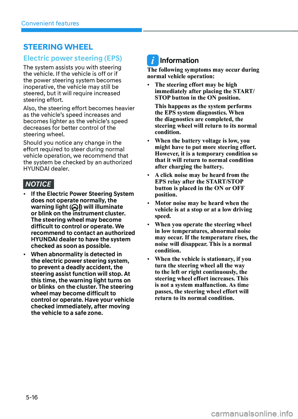
The system assists you with steering
the vehicle. If the vehicle is off or if
the power steering system becomes
inoperative, the vehicle may still be
steered, but it will require increased
steering effort.
Also, the steering effort becomes heavier
as the vehicle’s speed increases and
becomes lighter as the vehicle’s speed
decreases for better control of the
steering wheel.
Should you notice any change in the
effort required to steer during normal
vehicle operation, we recommend that
the system be checked by an authorized
HYUNDAI dealer.
NOTICE
• If the Electric Power Steering System
does not operate normally, the
warning light (
) will illuminate
or blink on the instrument cluster.
The steering wheel may become
difficult to control or operate. We
recommend to contact an authorized
HYUNDAI dealer to have the system
checked as soon as possible.
• When abnormality is detected in
the electric power steering system,
to prevent a deadly accident, the
steering assist function will stop. At
this time, the warning light turns on
or blinks on the cluster. The steering
wheel may become difficult to
control or operate. Have your vehicle
checked immediately, after moving
the vehicle to a safe zone.
Information
The following symptoms may occur during normal vehicle operation: • The steering effort may be high
immediately after placing the START/
STOP button in the ON position. This happens as the system performs
the EPS system diagnostics. When
the diagnostics are completed, the
steering wheel will return to its normal condition.
• When the battery voltage is low, you
might have to put more steering effort.
However, it is a temporary condition so
that it will return to normal condition
after charging the battery.
• A click noise may be heard from the
EPS relay after the START/STOP
button is placed in the ON or OFF position.
• Motor noise may be heard when the
vehicle is at a stop or at a low driving speed.
• When you operate the steering wheel
in low temperatures, abnormal noise
may occur. If the temperature rises, the
noise will disappear. This is a normal condition.
• When the vehicle is stationary, if you turn the steering wheel all the way
to the left or right continuously, the
steering wheel effort increases. This
is not a system malfunction. As time passes, the steering wheel effort will
return to its normal condition.
Page 512 of 548
Maintenance
9-36
Fuse/Relay panel description
Driver’s side fuse panel
OOSEV070013L
Inside the fuse/relay box covers, you can
find the fuse/relay label describing fuse/
relay names and ratings.
OOSEV091045N
Information
Not all fuse panel descriptions in this
manual may be applicable to your vehicle.
It is accurate at the time of printing. When
you inspect the fuse box on your vehicle,
refer to the fuse box label.
Page 513 of 548

09
9-37
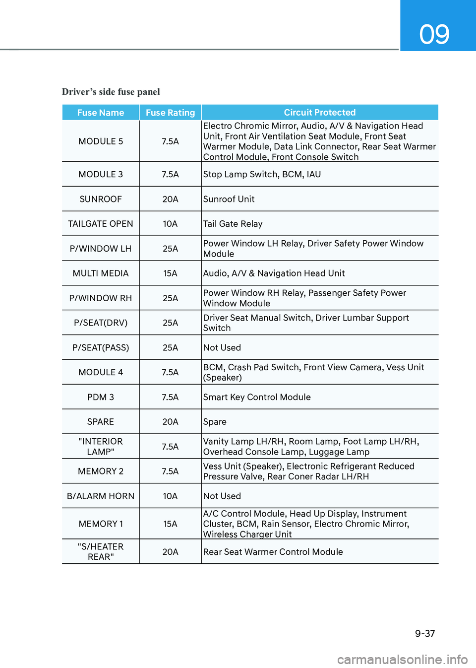
Driver’s side fuse panel
Fuse Name Fuse RatingCircuit Protected
MODULE 5 7.5AElectro Chromic Mirror, Audio, A/V & Navigation Head
Unit, Front Air Ventilation Seat Module, Front Seat
Warmer Module, Data Link Connector, Rear Seat Warmer
Control Module, Front Console Switch
MODULE 3 7.5A Stop Lamp Switch, BCM, IAU
SUNROOF 20ASunroof Unit
TAILGATE OpEN 10ATail Gate Relay
p/WINDOW LH 25A power Window LH Relay, Driver Safety power Window
Module
MULTI MEDIA 15A Audio, A/V & Navigation Head Unit
p/WINDOW RH 25A power Window RH Relay, passenger Safety power
Window Module
p/SEAT(DRV) 25A Driver Seat Manual Switch, Driver Lumbar Support
Switch
p/SEAT(pASS) 25A Not Used
MODULE 4 7.5A BCM, Crash pad Switch, Front View Camera, Vess Unit
(Speaker)
pDM 3 7.5A Smart Key Control Module
SpARE 20ASpare
"INTERIOR LAMp" 7.5AVanity Lamp LH/RH, Room Lamp, Foot Lamp LH/RH,
Overhead Console Lamp, Luggage Lamp
MEMORY 2 7.5A Vess Unit (Speaker), Electronic Refrigerant Reduced
pressure Valve, Rear Coner Radar LH/RH
B/ALARM HORN 10ANot Used
MEMORY 1 15A A/C Control Module, Head Up Display, Instrument
Cluster, BCM, Rain Sensor, Electro Chromic Mirror,
Wireless Charger Unit
"S/HEATER REAR" 20A
Rear Seat Warmer Control Module
Page 514 of 548
Maintenance
9-38
Fuse Name Fuse RatingCircuit Protected
AMp
30AAMp
MODULE 6 7.5A Smart Key Control Module, BCM, IAU MDpS 7.5A MDpS Unit
MODULE 1 7.5A Active Air Flap, Hazard Switch, Data Link Connector
MODULE 7 7.5A Front Air Ventilation Seat Module, Front Seat Warmer
Module, Rear Seat Warmer Control Module
A/BAG IND 7.5A A/C Control Module
BRAKE SWITCH 7.5A Stop Lamp Switch, Smart Key Control Module STA RT 7.5A Smart Key Control Module, EpCU
CLUSTER 7.5A Head Up Display, Instrument Cluster
DOOR LOCK 20ADoor Lock Relay, Door Unlock Relay, ICM Relay Box (Two
Turn Unlock Relay)
pDM 2 7.5A Driver/passenger Smart Key Outside Handle, BLE Unit,
IAU
FCA 10AFront Radar Unit
S/HEATER FRT 20AFront Seat Warmer Module, Front Air Ventilation Seat
Module
SpARE 10ASpare
A/C 7.5A A/C Control Module
pDM 1 15A Smart Key Control Module, Start/Stop Button
AIR BAG 15A SRS Control Module, passenger Occupant Detection Sensor
Driver’s side fuse Panel
Page 515 of 548
09
9-39
Fuse Name Fuse RatingCircuit Protected
IG1 25A pCB Block(Fuse - IEB 3, EpCU 2, E-SHIFTER 3)
MODULE 2 10ARear USB Charger, Smart Key Control Module, BCM,
Audio,A/V & Navigation Head Unit, power Outlet #1,
AMp, IAU, power Outside Mirror Switch
WASHER 15A Muntifunction Switch
WIpER (LO/HI) 10ABCM
WIpER RR 15A Rear Wiper Relay, Rear Wiper Motor
WIpER FRT 25A Front Wiper Motor, E/R Junction Block (Front Wiper(Low)
Relay)
HEATED MIRROR 10ADriver/passenger power Outside Mirror, A/C Control
Module
pOWER OUTLET 20Apower Outlet #2
SpARE 15A Spare
SpARE 15A Spare
Driver’s side fuse Panel
Page 516 of 548
Maintenance
9-40
Motor compartment fuse panel
OOSEV070016L
Inside the fuse/relay box covers, you can
find the fuse/relay label describing fuse/
relay names and ratings.
OOSEV091046N
Information
Not all fuse panel descriptions in this
manual may be applicable to your vehicle.
It is accurate at the time of printing. When
you inspect the fuse box on your vehicle,
refer to the fuse box label.
Page 517 of 548
09
9-41
Motor compartment fuse panel
TypeFuse Name Fuse
Rating Circuit Protected
MULTI
FUSE-3 LDC
150AE/R Junction Block (Fuse - IEB 1, IEB 2,
CHARGER 1, HEATED STEERING), EpCU (LDC)
MDpS 80AMDpS Unit
MULTI
FUSE-1 B+ 5
60ApCB Block ((Fuse - BATTERY MANAGEMENT 1,
HORN, EpCU 1), IG3 MAIN Relay)
B+ 2 60AIGpM ((Fuse - S/HEATER FRT), IpS0, IpS1, IpS2)
B+ 3 60AIGpM (IpS3, IpS5, IpS6, IpS7)
B+ 4 50AIGpM (Fuse - p/WINDOW LH, p/WINDOW
RH, TAILGATE OpEN, SUNROOF, AMp, p/SEAT
(DRV), p/SEAT (pASS), S/HEATER REAR)
COOLING FAN 60AE/R Junction Block (Cooling Fan Relay)
REAR HEATED 40AE/R Junction Block (Rear Heated Relay)
IG1 40AE/R Junction Block (pDM (IG1) 2 Relay, pDM
(ACC) 1 Relay)
IG2 40AE/R Junction Block (pDM (IG2) 3 Relay)
MULTI
FUSE-2 IEB 4
40AElectronic Brake Control Module
BLOWER 40AE/R Junction Block (Blower Relay)
Page 518 of 548
Maintenance
9-42
TypeFuse Name Fuse
Rating Circuit Protected
FUSEOBC
10AOBC
CHARGER 2 10AICM Relay Box (Charge Connector Lock/Unlock
Relay), CCM Unit
IG3 2 20AE/R Junction Block (IG3 1 Relay, IG3 2 Relay)
B+ 1 40AIGpM ((Fuse - BRAKE SWITCH, MODULE 1,
pDM 1, pDM 2, DOOR LOCK), Leak Current
Autocut Device)
E-SHIFTER 1 40AE/R Junction Block (Fuse - E-SHIFTER 2,
E-Shifter Relay)
CHARGER 1 10ACharge Connector Door Module
IEB 1 40AElectronic Brake Control Module, Multipurpose
Check Connector
IEB 2 40AElectronic Brake Control Module