2022 HYUNDAI KONA EV battery replacement
[x] Cancel search: battery replacementPage 192 of 548
Convenient features
5-8
Information
Changes or modifications not expressly
approved by the party responsible
for compliance could void the user’s authority to operate the equipment. If the keyless entry system is inoperative due
to changes or modifications not expressly
approved by the party responsible for
compliance, it will not be covered by your
manufacturer’s vehicle warranty.
Information
This device complies with Industry Canada RSS-210 standard.
Operation is subject to the following three conditions: 1. This device may not cause harmful
interference, and
2. This device must accept any
interference received, including
interference that may cause undesired operation.
3. Changes or modifications not expressly
approved by the party responsible
for compliance could void the user’s authority to operate the device.
NOTICE
Keep the smart key away from
electromagnetic materials that blocks
electromagnetic waves to the key
surface.
NOTICE
Always have the smart key with you
when leaving the vehicle. If the smart
key is left near the vehicle, the vehicle
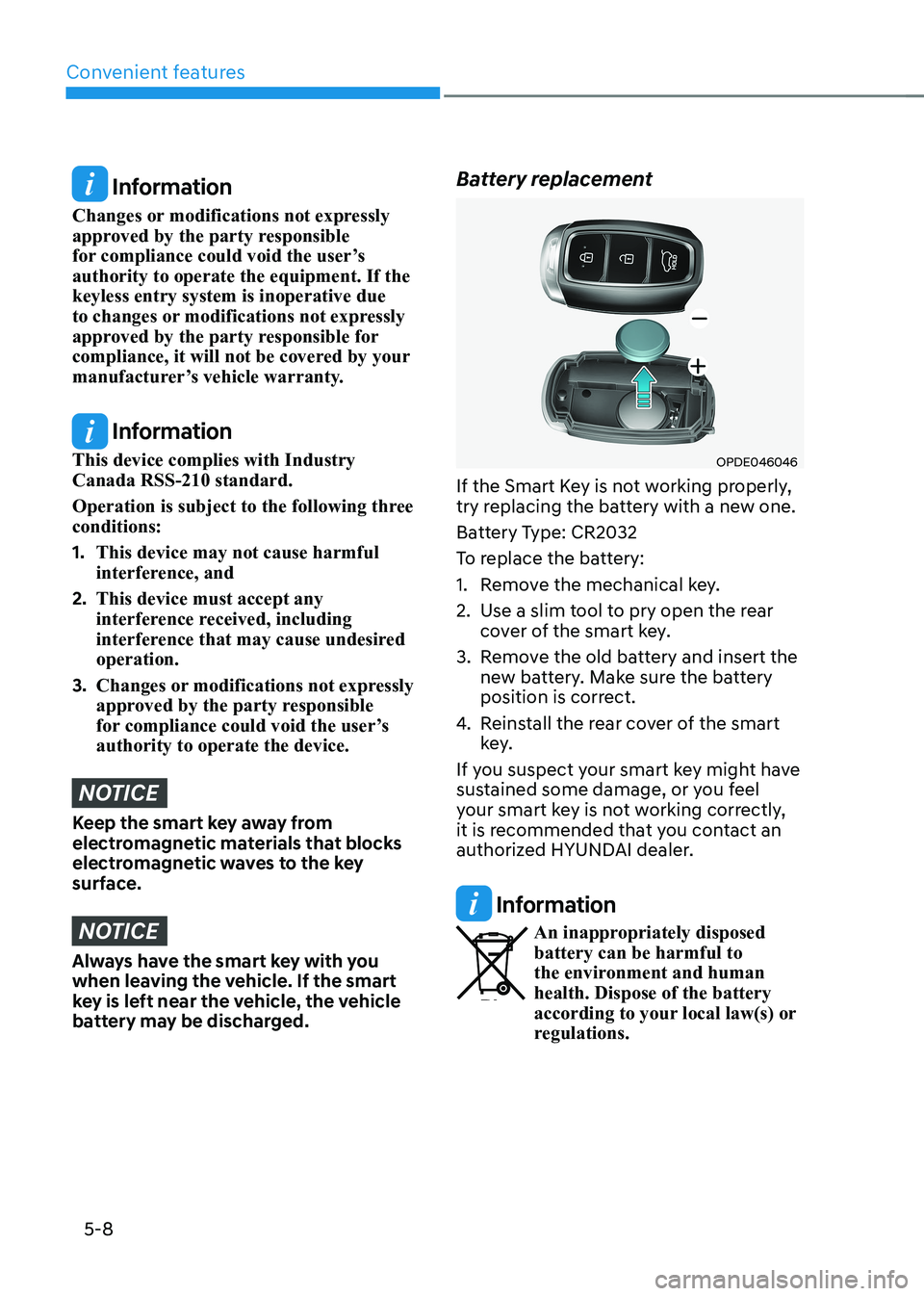
battery may be discharged. Battery replacement
OPDE046046
If the Smart Key is not working properly,
try replacing the battery with a new one.
Battery Type: CR2032
To replace the battery:
1. Remove the mechanical key.
2. Use a slim tool to pry open the rear cover of the smart key.
3. Remove the old battery and insert the new battery. Make sure the battery
position is correct.
4. Reinstall the rear cover of the smart
key.
If you suspect your smart key might have
sustained some damage, or you feel
your smart key is not working correctly,
it is recommended that you contact an
authorized HYUNDAI dealer.
Information
An inappropriately disposed battery can be harmful to
the environment and human health. Dispose of the battery
according to your local law(s) or
regulations.
Page 234 of 548
Convenient features
5-50
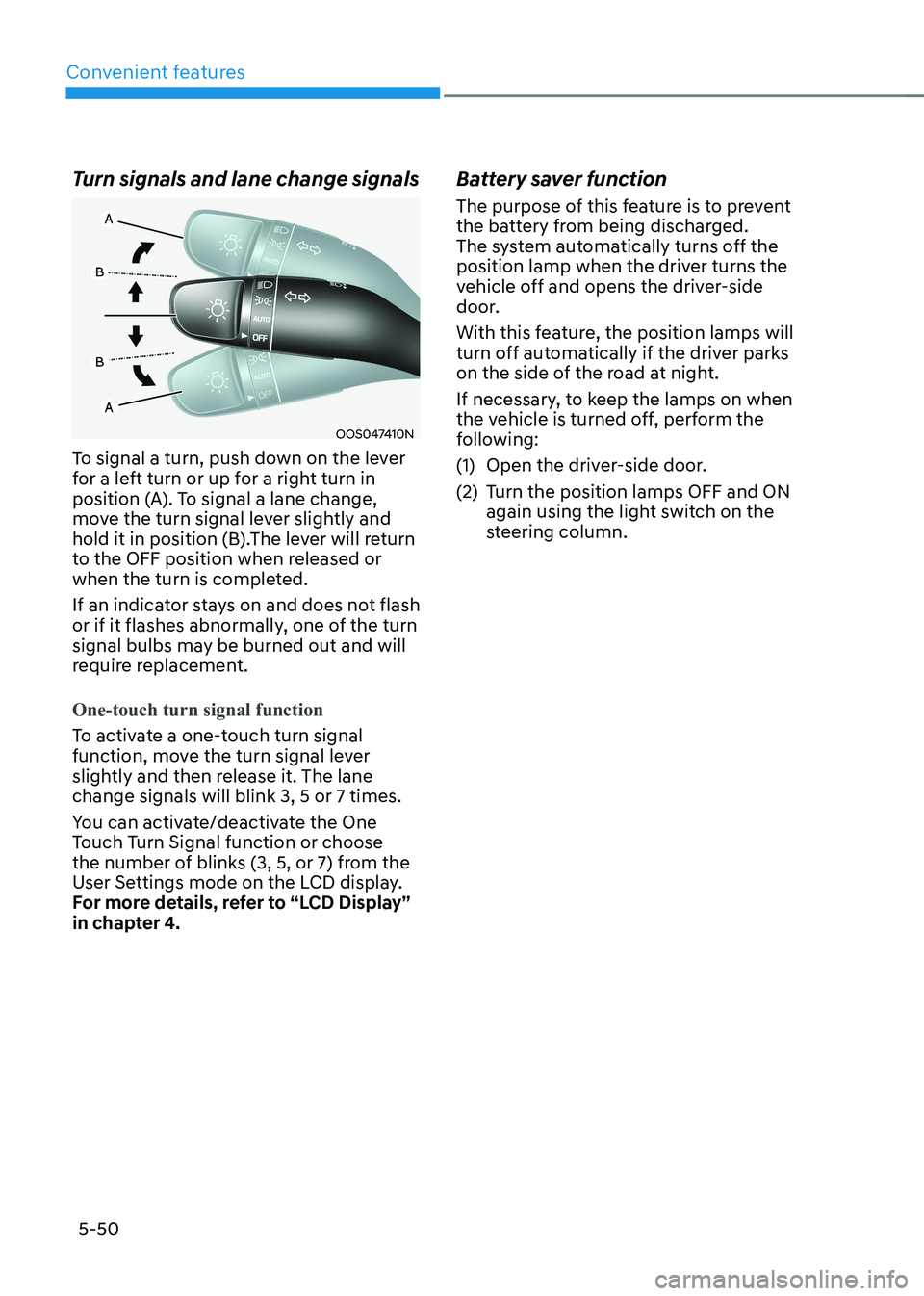
Turn signals and lane change signals
OOS047410N
To signal a turn, push down on the lever
for a left turn or up for a right turn in
position (A). To signal a lane change,
move the turn signal lever slightly and
hold it in position (B).The lever will return
to the OFF position when released or
when the turn is completed.
If an indicator stays on and does not flash
or if it flashes abnormally, one of the turn
signal bulbs may be burned out and will
require replacement.
One-touch turn signal function
To activate a one-touch turn signal
function, move the turn signal lever
slightly and then release it. The lane change signals will blink 3, 5 or 7 times.
You can activate/deactivate the One
Touch Turn Signal function or choose
the number of blinks (3, 5, or 7) from the
User Settings mode on the LCD display.
For more details, refer to “LCD Display”
in chapter 4. Battery saver function
The purpose of this feature is to prevent
the battery from being discharged.
The system automatically turns off the
position lamp when the driver turns the
vehicle off and opens the driver-side
door.
With this feature, the position lamps will
turn off automatically if the driver parks
on the side of the road at night.
If necessary, to keep the lamps on when
the vehicle is turned off, perform the
following:
(1) Open the driver-side door.
(2) Turn the position lamps OFF and ON
again using the light switch on the
steering column.
Page 477 of 548
9
9. Maintenance
Motor compartment ......................................................................................... 9-3
Maintenance services ....................................................................................... 9-4
Owner’s responsibility ................................................................................................ 9-4
Owner maintenance precautions............................................................................... 9-4
Owner maintenance ......................................................................................... 9-5
Owner maintenance schedule .................................................................................... 9-5
Scheduled maintenance services ..................................................................... 9 -7
Maintenance Schedule ................................................................................................ 9 -7
Explanation of scheduled maintenance items ...............................................9-9
Cooling system ............................................................................................................ 9-9
Coolant ......................................................................................................................... 9-9
Reduction gear fluid.................................................................................................... 9-9
Brake hoses and lines.................................................................................................. 9-9Brake fluid ................................................................................................................... 9-9
Brake pads, calipers and rotors .................................................................................. 9-9
Suspension mounting bolts ........................................................................................ 9-9
Drive shafts and boots ................................................................................................ 9-9
Air conditioning refrigerant/compressor................................................................... 9-9
Coolant ............................................................................................................. 9-10
Brake fluid ......................................................................................................... 9-11
Checking the brake fluid level .................................................................................... 9-11
Washer fluid ..................................................................................................... 9-12
Checking the washer fluid level ................................................................................ 9-12
Climate control air filter................................................................................... 9-13
Filter inspection ............................................................................................... 9-13
Filter replacement ...................................................................................................... 9-13
Wiper blades .................................................................................................... 9-14
Blade inspection ......................................................................................................... 9-14
Blade replacement ................................................................................................... 9-14
Battery (12 Volt) ................................................................................................ 9-17
Battery usage.............................................................................................................. 9-18 Battery capacity label ................................................................................................ 9-18
Battery recharging ..................................................................................................... 9-18
Reset items ................................................................................................................. 9-19
Page 508 of 548
![HYUNDAI KONA EV 2022 Owners Manual Maintenance
9-32
FUSES
„„Blade type
AB
„
„Cartridge type
„
„Multi fuse
OTM078035
AB
AB
[A] : Normal, [B] : Blown
A vehicle’s electrical system is protected
from elect HYUNDAI KONA EV 2022 Owners Manual Maintenance
9-32
FUSES
„„Blade type
AB
„
„Cartridge type
„
„Multi fuse
OTM078035
AB
AB
[A] : Normal, [B] : Blown
A vehicle’s electrical system is protected
from elect](/manual-img/35/56171/w960_56171-507.png)
Maintenance
9-32
FUSES
„„Blade type
AB
„
„Cartridge type
„
„Multi fuse
OTM078035
AB
AB
[A] : Normal, [B] : Blown
A vehicle’s electrical system is protected
from electrical overload damage by fuses.
This vehicle has 2 (or 3) fuse panels, one
located in the driver’s side panel bolster,
the other in the motor compartment.
If any of your vehicle’s lights,
accessories, or controls do not work,
check the appropriate circuit fuse. If a
fuse has blown, the element inside the
fuse will be melted or broken.
If the electrical system does not work,
first check the driver’s side fuse panel.
Before replacing a blown fuse, turn the
vehicle and all switches off, and then
disconnect the negative battery cable.
Always replace a blown fuse with one of
the same rating.
If the replacement fuse blows, this
indicates an electrical problem.
Avoid using the system involved and it is
recommended to consult an authorized
dealer.
Information
Three kinds of fuses are used: blade type
for lower amperage rating, cartridge
type, and multi fuse for higher amperage ratings.
WARNING
NEVER replace a fuse with anything but
another fuse of the same rating. • A higher capacity fuse could cause
damage and possibly cause a fire.
• Do not install a wire or aluminum
foil instead of the proper fuse -
even as a temporary repair. It may
cause extensive wiring damage and
possibly a fire.
NOTICE
Do not use a screwdriver or any other
metal object to remove fuses because
it may cause a short circuit and damage
the system.
Page 511 of 548
09
9-35
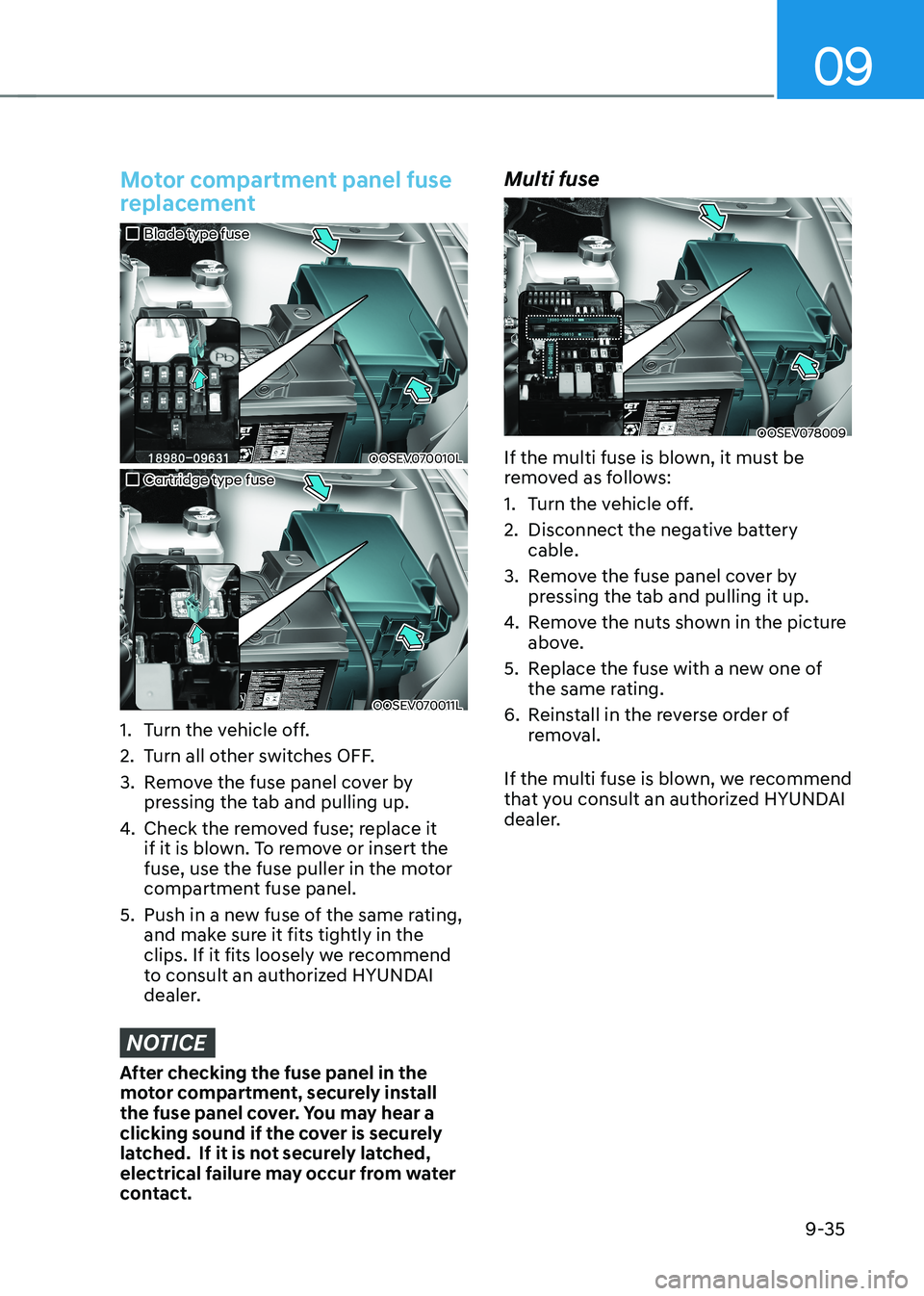
Motor compartment panel fuse
replacement
„„Blade type fuse
OOSEV070010L
„„Cartridge type fuse
OOSEV070011L
1. Turn the vehicle off.
2. Turn all other switches OFF.
3. Remove the fuse panel cover by pressing the tab and pulling up.
4. Check the removed fuse; replace it
if it is blown. To remove or insert the
fuse, use the fuse puller in the motor
compartment fuse panel.
5. push in a new fuse of the same rating, and make sure it fits tightly in the
clips. If it fits loosely we recommend
to consult an authorized HYUNDAI
dealer.
NOTICE
After checking the fuse panel in the
motor compartment, securely install
the fuse panel cover. You may hear a
clicking sound if the cover is securely
latched. If it is not securely latched,
electrical failure may occur from water
contact. Multi fuse
OOSEV078009
If the multi fuse is blown, it must be
removed as follows:
1. Turn the vehicle off.
2. Disconnect the negative battery cable.
3. Remove the fuse panel cover by pressing the tab and pulling it up.
4. Remove the nuts shown in the picture
above.
5. Replace the fuse with a new one of the same rating.
6. Reinstall in the reverse order of removal.
If the multi fuse is blown, we recommend
that you consult an authorized HYUNDAI
dealer.
Page 521 of 548
09
9-45
Headlamp, position lamp, turn
signal lamp and daytime running
light bulb replacement
Type A
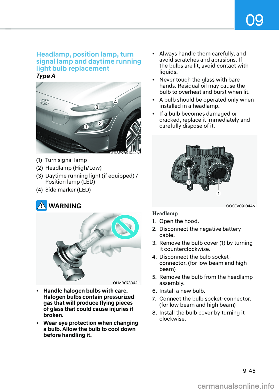
OOSEV091042N
(1) Turn signal lamp
(2) Headlamp (High/Low)
(3) Daytime running light (if equipped) / position lamp (LED)
(4) Side marker (LED)
WARNING
OLMB073042L
• Handle halogen bulbs with care.
Halogen bulbs contain pressurized
gas that will produce flying pieces
of glass that could cause injuries if
broken.
• Wear eye protection when changing
a bulb. Allow the bulb to cool down
before handling it. •
Always handle them carefully, and
avoid scratches and abrasions. If
the bulbs are lit, avoid contact with liquids.
• Never touch the glass with bare
hands. Residual oil may cause the
bulb to overheat and burst when lit.
• A bulb should be operated only when
installed in a headlamp.
• If a bulb becomes damaged or
cracked, replace it immediately and
carefully dispose of it.
OOSEV091044N
Headlamp
1. Open the hood.
2. Disconnect the negative battery
cable.
3. Remove the bulb cover (1) by turning it counterclockwise.
4. Disconnect the bulb socket-
connector. (for low beam and high
beam)
5. Remove the bulb from the headlamp assembly.
6. Install a new bulb.
7. Connect the bulb socket-connector.
(for low beam and high beam)
8. Install the bulb cover by turning it clockwise.