Page 545 of 659

7-32
Maintenance
E
E X
X P
P L
L A
A N
N A
A T
T I
I O
O N
N
O
O F
F
S
S C
C H
H E
E D
D U
U L
L E
E D
D
M
M A
A I
I N
N T
T E
E N
N A
A N
N C
C E
E
I
I T
T E
E M
M S
S
Engine oil and filter
The engine oil and filter should be
changed at the intervals specified in
the maintenance schedule. If the car
is being driven in severe conditions,
more frequent oil and filter changes
are required.
Drive belts
Inspect all drive belts for evidence of
cuts, cracks, excessive wear or oil
saturation and replace if necessary.
Drive belts should be checked peri-
odically for proper tension and
adjusted as necessary.
Fuel filter (cartridge)
A clogged-up fuel filter may limit the
vehicle driving speed, damage the
emission system, and cause the
hard starting. When a considerable
amount of foreign substances are
accumulated in the fuel tank, the fuel
filter should be replaced.
Upon installing a new fuel filter, oper-
ate the diesel engine for several min-
utes, and check the connections for
any leakages. We recommend you to
have the fuel filter replaced by an
authorized HYUNDAI dealer.
Fuel lines, fuel hoses and con-
nections
Check the fuel lines, fuel hoses and
connections for leakage and dam-
age. We recommend that the fuel
lines, fuel hoses and connections be
replaced by an authorized HYUNDAI
dealer.
Vapor hose and fuel filler cap
The vapor hose and fuel filler cap
should be inspected at those inter-
vals specified in the maintenance
schedule. Make sure that a new
vapor hose or fuel filler cap is cor-
rectly replaced.
Vacuum crankcase ventilation
hoses (if equipped)
Inspect the surface of hoses for evi-
dence of heat and/or mechanical
damage. Hard and brittle rubber,
cracking, tears, cuts, abrasions, and
excessive swelling indicate deterio-
ration. Particular attention should be
paid to examine those hose surfaces
nearest to high heat sources, such
as the exhaust manifold.
Inspect the hose routing to assure
that the hoses do not come in con-
tact with any heat source, sharp
edges or moving component which
might cause heat damage or
mechanical wear. Inspect all hose
connections, such as clamps and
couplings, to make sure they are
secure, and that no leaks are pres-
ent. Hoses should be replaced
immediately if there is any evidence
of deterioration or damage.
When you are inspecting the belt,
place the ignition switch to the
LOCK/OFF or ACC position.
CAUTION
Page 554 of 659

7-41
7
Maintenance
W
W A
A S
S H
H E
E R
R
F
F L
L U
U I
I D
D
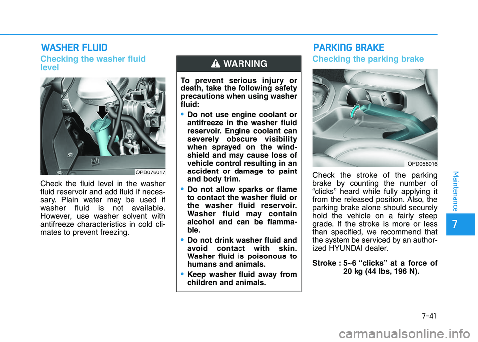
Checking the washer fluid
level
Check the fluid level in the washer
fluid reservoir and add fluid if neces-
sary. Plain water may be used if
washer fluid is not available.
However, use washer solvent with
antifreeze characteristics in cold cli-
mates to prevent freezing.
Checking the parking brake
Check the stroke of the parking
brake by counting the number of
“clicks’’ heard while fully applying it
from the released position. Also, the
parking brake alone should securely
hold the vehicle on a fairly steep
grade. If the stroke is more or less
than specified, we recommend that
the system be serviced by an author-
ized HYUNDAI dealer.
Stroke : 5~6 “clicks’’ at a force of
20 kg (44 lbs, 196 N).OPD076017
P
P A
A R
R K
K I
I N
N G
G
B
B R
R A
A K
K E
E
OPD056016
To prevent serious injury or
death, take the following safety
precautions when using washer
fluid:
Do not use engine coolant or
antifreeze in the washer fluid
reservoir. Engine coolant can
severely obscure visibility
when sprayed on the wind-
shield and may cause loss of
vehicle control resulting in an
accident or damage to paint
and body trim.
Do not allow sparks or flame
to contact the washer fluid or
the washer fluid reservoir.
Washer fluid may contain
alcohol and can be flamma-
ble.
Do not drink washer fluid and
avoid contact with skin.
Washer fluid is poisonous to
humans and animals.
Keep washer fluid away from
children and animals.
WARNING
Page 562 of 659

7-49
7
Maintenance
When you do not use the vehiclefor a long time in a low tempera-
ture area, disconnect the battery
and keep it indoors.
Always charge the battery fully to prevent battery case damage
in low temperature areas.
If you connect unauthorized elec-
tronic devices to the battery, the
battery may be discharged. Never
use unauthorized devices.
For best battery service
Keep the battery securely mounted.
Keep the battery top clean and dry.
Keep the terminals and connec- tions clean, tight, and coated with
petroleum jelly or terminal grease.
Rinse any spilled electrolyte from the battery immediately with a
solution of water and baking soda.
If the vehicle is not going to be used for an extended time, discon-
nect the battery cables.
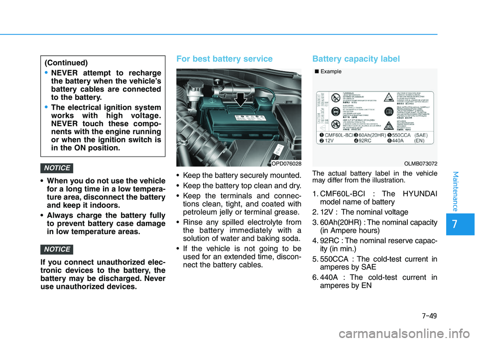
Battery capacity label
The actual battery label in the vehicle
may differ from the illustration.
1. CMF60L-BCI : The HYUNDAI model name of battery
2. 12V : The nominal voltage
3. 60Ah(20HR) : The nominal capacity (in Ampere hours)
4. 92RC : The nominal reserve capac- ity (in min.)
5. 550CCA : The cold-test current in amperes by SAE
6. 440A : The cold-test current in amperes by EN
NOTICE
NOTICEOPD076028
(Continued)
NEVER attempt to recharge
the battery when the vehicle’s
battery cables are connected
to the battery.
The electrical ignition system
works with high voltage.
NEVER touch these compo-
nents with the engine running
or when the ignition switch is
in the ON position.
OLMB073072
■
Example
Page 578 of 659

7-65
7
Maintenance
4. Check the removed fuse; replace itif it is blown. To remove or insert
the fuse, use the fuse puller in the
engine compartment fuse panel.
5. Push in a new fuse of the same rating, and make sure it fits tightly
in the clips. If it fits loosely, consult
an authorized HYUNDAI dealer.
After checking the fuse panel in
the engine compartment, securely
install the fuse panel cover. You
may hear a clicking sound if the
cover is securely latched. If it is
not securely latched, electrical
failure may occur from water con-
tact.Main fuse
The electronic system may not func-
tion correctly even when the fuses
located in the engine compartment
and instrument panel are not discon-
nected. In such case, the cause of
the problem may be disconnection of
the main fuse (BFT type), which is
located inside the positive battery
terminal (+) cap. Since the main fuse
is designed more intricately than
other parts, we recommend you visit
the nearest HYUNDAI dealer.
Information
After inspection always securely
install the battery cap. If it is not
securely latched, electrical failure may
occur from water contact.
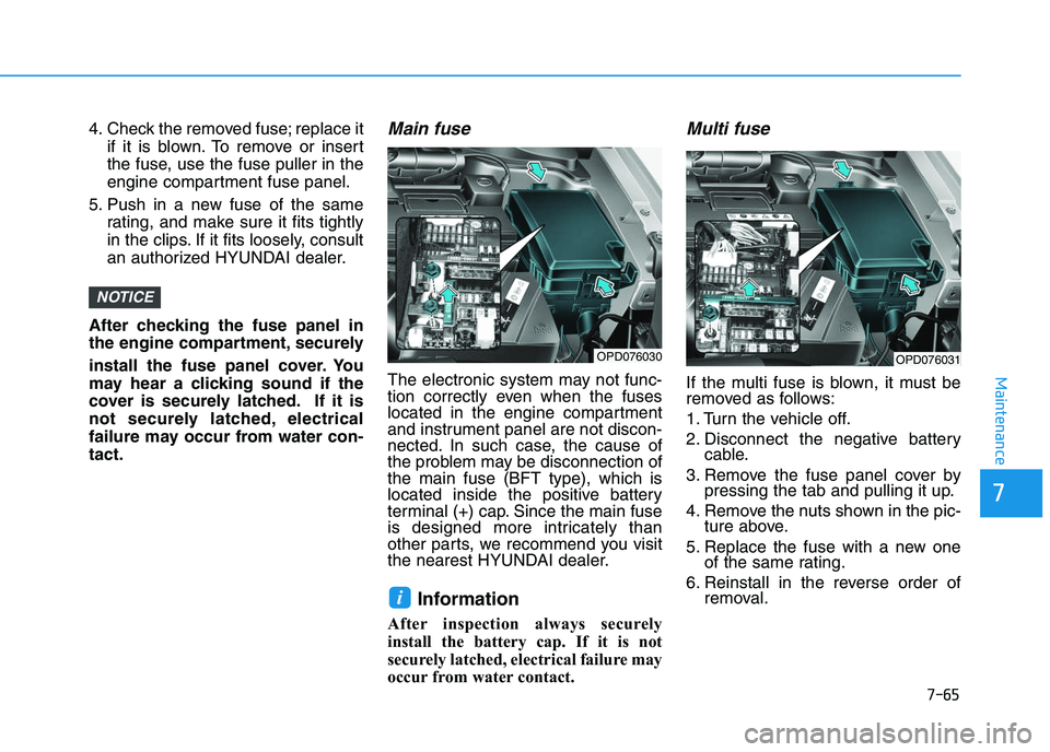
Multi fuse
If the multi fuse is blown, it must be
removed as follows:
1. Turn the vehicle off.
2. Disconnect the negative battery cable.
3. Remove the fuse panel cover by pressing the tab and pulling it up.
4. Remove the nuts shown in the pic- ture above.
5. Replace the fuse with a new one of the same rating.
6. Reinstall in the reverse order of removal.
i
NOTICE
OPD076030OPD076031
Page 589 of 659
7-76
Maintenance
Fuse No.Fuse NameSymbolFuse RatingCircuit Protected
F37SENSOR 2S210ARCV Control Solenoid Valve , Purge Control Solenoid Valve, Oil Control Valve #1/#2,
A/Con Relay, E/R Junction Block (RLY.9)
F38ECU 2E210AECM
F39ECU 1E120AECM
F40INJECTORINJECTOR15A-
F41SENSOR 1S115AOxygen Sensor (Up), Oxygen Sensor (Down)
F42IGNITION
COILIGN
COIL20AIgnition Coil #1/#2/#3
F43ECU 3E 315AECM
F44A/CON10AA/Con Relay
F45ECU 5E510AECM
F46SENSOR 4S415A-
F47ABS 3310AABS/ESP Control Module, Multipurpose Check Connector
Engine compartment fuse panel
■ Kappa 1.0 T-GDI
Page 590 of 659
7-77
7
Maintenance
Fuse No.Fuse NameSymbolFuse RatingCircuit Protected
F48TCU 2T215AE/R Junction Block (Fuse : F34)
F49SENSOR 3S310AE/R Junction Block (RLY.7)
F50ECU 4E415AECM
F51WIPER25AWiper Relay
F52HORN15AHorn Relay
Engine compartment fuse panel
■ Kappa 1.0 T-GDI
Fuse No.Fuse NameSymbolFuse RatingCircuit Protected
F37SENSOR 2S210ARCV Control Solenoid Valve , Purge Control Solenoid Valve, Oil Control Valve #1/#2,
A/Con Relay, E/R Junction Block (RLY.9)
F38ECU 2E210AECM
F39ECU 1E120AECM
F40INJECTORINJECTOR15A-
F41SENSOR 1S115AOxygen Sensor (Up), Oxygen Sensor (Down)
■ Kappa 1.4 T-GDI
Page 591 of 659
7-78
Maintenance
Fuse No.Fuse NameSymbolFuse RatingCircuit Protected
F42IGNITIONCOILIGN
COIL20AIgnition Coil #1/#2/#3/#4
F43ECU 3E 315AECM
F44A/CON10AA/Con Relay
F45ECU 5E510AECM
F46SENSOR 4S415AVacuum Pump
F47ABS 3310AABS/ESP Control Module, Multipurpose Check Connector
F48TCU 2T215ATCM, Transaxle Range Switch, E/R Junction Block (Fuse : F34)
F49SENSOR 3S310AE/R Junction Block (RLY.7)
F50ECU 4E415AECM
F51WIPER25AWiper Relay
F52HORN15AHorn Relay
Engine compartment fuse panel
■ Kappa 1.4 T-GDI
Page 592 of 659
7-79
7
Maintenance
Engine compartment fuse panel
Fuse No.Fuse NameSymbolFuse RatingCircuit Protected
F37SENSOR 2S210ACamshaft Position Sensor #1/#2, Purge Control Solenoid Valve,
Oil Control Valve #1/#2, Variable Intake Solenoid Valve,
E/R Junction Block (RLY.1, RLY.2)
F38ECU 2E210AECM
F39ECU 1E120AECM
F40INJECTORINJECTOR15AInjector #1/#2/#3/#4
F41SENSOR 1S115AOxygen Sensor (Up), Oxygen Sensor (Down)
F42IGNITION
COILIGN
COIL20AIgnition Coil #1/#2/#3/#4, Condenser
F43ECU 3E 315AECM
F44A/CON10A-
F45ECU 5E510AECM
F46SENSOR 4S415A-
F47ABS 3310AABS/ESP Control Module, Multipurpose Check Connector
■ Kappa 1.4 MPI