Page 293 of 444

7-46
Driving your vehicle
Emergency Stop Signal (ESS)
The Emergency Stop Signal system
alerts the driver behind by blinking the
stop light when the vehicle is braked
rapidly and severely.
The system is activated when:
• The vehicle suddenly stops (vehicle
speed is over 55 km/h and the vehicle
deceleration at greater than 7 m/s
2)
• The ABS is activating
When the vehicle speed is under 40
km/h and the ABS deactivates or the
sudden stop situation is over, the stop
light blinking will stop. Instead, the
hazard warning flasher will turn on
automatically.
The hazard warning flasher will turn off
when vehicle speed is over 10 km/h after
the vehicle has stopped. Also, it will turn
off when the vehicle is driven at low
speed for some time. You can turn it off
manually by pushing the hazard warning
flasher switch.
CAUTION
The Emergency Stop Signal (ESS)
system will not work if the hazard
warning flasher is already on.
Good braking practices
WARNING
Whenever leaving the vehicle or
parking, always come to a complete
stop and continue to depress the brake
pedal. Move the shift lever into the 1st
gear (for manual transmission vehicle)
or N (Neutral) position (for Automated
Manual Transmission vehicle), then
apply the parking brake, and place
the ignition switch in the LOCK/OFF
position.
Vehicles with the parking brake not
fully engaged are at risk for moving
inadvertently and causing injury to
yourself or others.
Wet brakes can be dangerous! The
brakes may get wet if the vehicle is
driven through standing water or if it is
washed. Your vehicle will not stop as
quickly if the brakes are wet. Wet brakes
may cause the vehicle to pull to one
side.
To dry the brakes, apply the brakes
lightly until the braking action returns to
normal, taking care to keep the vehicle
under control at all times. If the braking
action does not return to normal, stop
as soon as it is safe to do so and we
recommend that you call an authorized
HYUNDAI dealer for assistance.
DO NOT drive with your foot resting on
the brake pedal. Even light, but constant
pedal pressure can result in the brakes
overheating, brake wear, and possibly
even brake failure.
Page 314 of 444

Driver assistance system
8-12
• Reverse Parking Distance Warning
may malfunction when:
- Heavy rain or water spray is present
- Water flows on the surface of the
sensor
- Affected by another vehicle’s sensors
- The sensor is covered with snow
- Driving on uneven road, gravel roads
or bushes
- Objects that generates ultrasonic
waves are near the sensor
- Installing the license plate differently
from the original location
- The vehicle bumper height or
ultrasonic sensor installation has
been modified
- Attaching equipments or accessories
around the ultrasonic sensors
• The following objects may not be
detected:
- Sharp or slim objects, such as ropes,
chains or small poles.
- Objects, which tend to absorb sensor
frequency, such as clothes, spongy
material or snow.
- Objects smaller than 100 cm (40 in.)
in length and narrower than 14 cm (6
in.) in diameter.
- Pedestrians, animals or objects
that are very close to the ultrasonic
sensors
• Parking Distance Warning Indicators
may be displayed differently from
the actual detected location when
the obstacle is located between the
sensors.
• Parking Distance Warning indicator
may not occur sequentially depending
on vehicle speed or obstacle shape.
• If Reverse Parking Distance Warning
needs repair, we recommend that the
system be inspected by an authorized
HYUNDAI dealer.
Page 330 of 444

9-16
Emergency situations
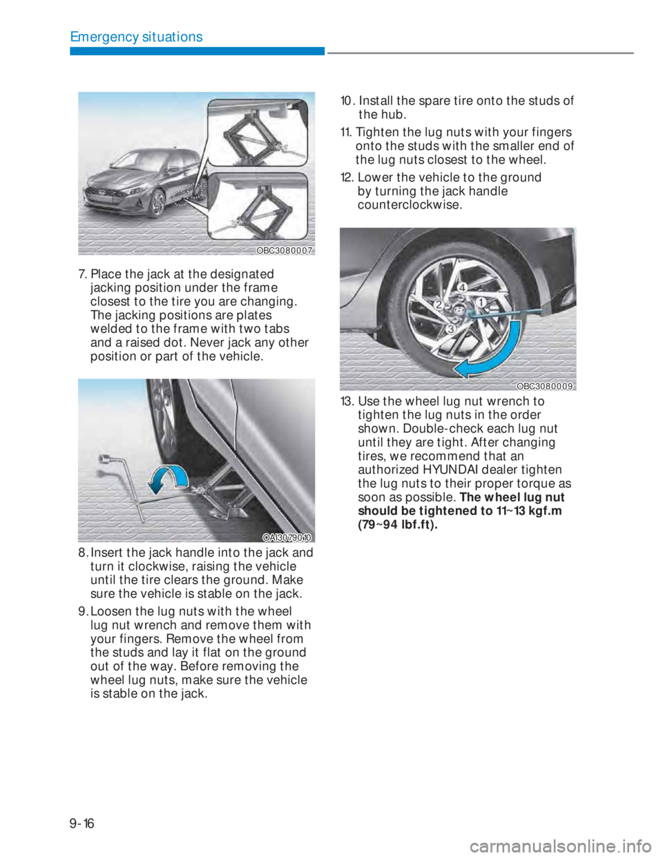
OBC3080007OBC3080007
7. Place the jack at the designated
jacking position under the frame
closest to the tire you are changing.
The jacking positions are plates
welded to the frame with two tabs
and a raised dot. Never jack any other
position or part of the vehicle.
OAI3079010OAI3079010
8. Insert the jack handle into the jack and
turn it clockwise, raising the vehicle
until the tire clears the ground. Make
sure the vehicle is stable on the jack.
9. Loosen the lug nuts with the wheel
lug nut wrench and remove them with
your fingers. Remove the wheel from
the studs and lay it flat on the ground
out of the way. Before removing the
wheel lug nuts, make sure the vehicle
is stable on the jack.10. Install the spare tire onto the studs of
the hub.
11. Tighten the lug nuts with your fingers
onto the studs with the smaller end of
the lug nuts closest to the wheel.
12. Lower the vehicle to the ground
by turning the jack handle
counterclockwise.
OBC3080009OBC3080009
13. Use the wheel lug nut wrench to
tighten the lug nuts in the order
shown. Double-check each lug nut
until they are tight. After changing
tires, we recommend that an
authorized HYUNDAI dealer tighten
the lug nuts to their proper torque as
soon as possible. The wheel lug nut
should be tightened to 11~13 kgf.m
(79~94 lbf.ft).
Page 395 of 444

10-56
Maintenance
Tire replacement
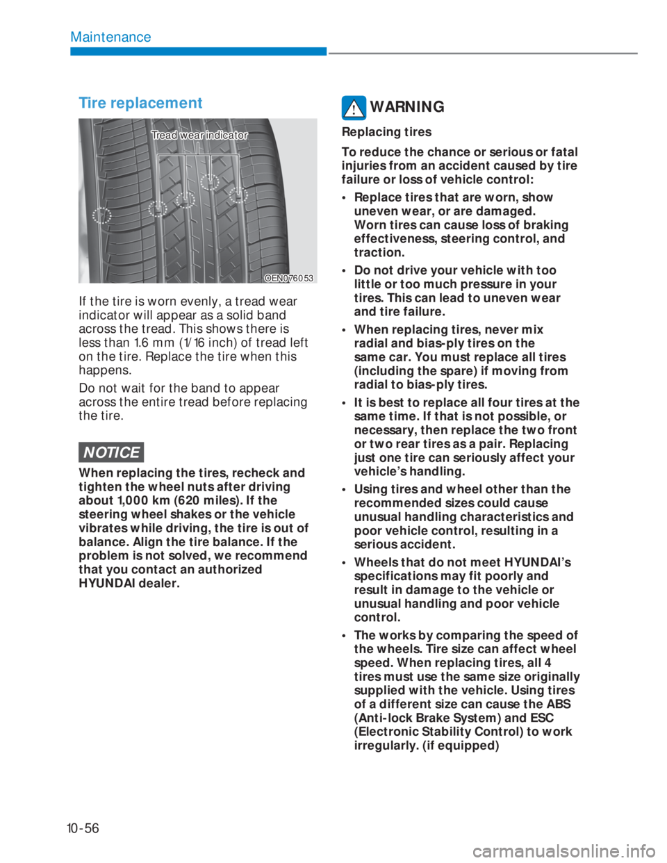
OEN076053OEN076053
Tread wear indicatorTread wear indicator
If the tire is worn evenly, a tread wear
indicator will appear as a solid band
across the tread. This shows there is
less than 1.6 mm (1/16 inch) of tread left
on the tire. Replace the tire when this
happens.
Do not wait for the band to appear
across the entire tread before replacing
the tire.
NOTICE
When replacing the tires, recheck and
tighten the wheel nuts after driving
about 1,000 km (620 miles). If the
steering wheel shakes or the vehicle
vibrates while driving, the tire is out of
balance. Align the tire balance. If the
problem is not solved, we recommend
that you contact an authorized
HYUNDAI dealer.
WARNING
Replacing tires
To reduce the chance or serious or fatal
injuries from an accident caused by tire
failure or loss of vehicle control:
• Replace tires that are worn, show
uneven wear, or are damaged.
Worn tires can cause loss of braking
effectiveness, steering control, and
traction.
• Do not drive your vehicle with too
little or too much pressure in your
tires. This can lead to uneven wear
and tire failure.
• When replacing tires, never mix
radial and bias-ply tires on the
same car. You must replace all tires
(including the spare) if moving from
radial to bias-ply tires.
• It is best to replace all four tires at the
same time. If that is not possible, or
necessary, then replace the two front
or two rear tires as a pair. Replacing
just one tire can seriously affect your
vehicle’s handling.
• Using tires and wheel other than the
recommended sizes could cause
unusual handling characteristics and
poor vehicle control, resulting in a
serious accident.
• Wheels that do not meet HYUNDAI’s
specifications may fit poorly and
result in damage to the vehicle or
unusual handling and poor vehicle
control.
• The works by comparing the speed of
the wheels. Tire size can affect wheel
speed. When replacing tires, all 4
tires must use the same size originally
supplied with the vehicle. Using tires
of a different size can cause the ABS
(Anti-lock Brake System) and ESC
(Electronic Stability Control) to work
irregularly. (if equipped)
Page 407 of 444
10-68
Maintenance
Fuse NameSymbolFuse
ratingCircuit Protected
A/C 37.5A MTC,FATC,ECU
DOOR LOCK
20A DOOR ACTUATOR
MODULE 5
10AAT_LEVER_IND, HLLD, ‘SEAT_EXTN_DRV, ‘AUDIO, AMP,
‘MTC/FATC, ECM_MIRR, ‘WIRELESS CHARGER
ABS 3
10A ABS (ANTI-LOCK BRAKE SYSTEM)
BRAKE
SWITCH
7.5A STOP SWITCH
START1
7.5A START RLY
CLUSTER
10A CLUSTER
MODULE 4
10A C_PAD_SW(ESC SW)
IBU 2
15A IBU (INTEGRATED BODY CONTROL UNIT)
ACC 1
10AAMP, O_S_MIRR_SW, AUDIO/AVN, IBU(BCM), VDMS,
REAR USB, USB_CHARGER
MODULE 7
10A MULTI FUNCTION SWITCH
WASHER
15A M/F (WASHER PWR)
MODULE 6
7.5A IBU
Inner Compartment Fuse Panel (ICU)
Page 411 of 444
10-72
Maintenance
Engine Compartment Fuse Panel (1.0 T-GDi)
Fuse Name SymbolFuse
RatingCircuit Protected
BATT250A ICU Junction Block (IPS2, IPS4, IPS6, IPS9, IPS10)
IG2
40AE/R Junction Block (RLY.9).
[With Smart Key] PDM Relay Box (IG2 Relay)
[W/O Smart Key] Ignition Switch
C/FAN
60A E/R Junction Block (RLY.2)
IGN COIL
20A Ignition Coil #1/#2/#3
ECU5
20A ECU
SENSOR 1
10AE/R Junction Block (RLY.2/3),
Oil Control Valve #1/#2 (Intake/Exhaust),
Purge Control Solenoid Valve
SENSOR 2
10A Oxygen Sensor (Up/Down)
RR DEFOG
40A ICU Junction Block (Rear Defogger Relay)
ABS 1
40A ABS/ESP Control Module
ABS 2
30A ABS/ESP Control Module
BLOWER
40A E/R Junction Block (RLY.10)
WIPER 2
10A E/R Junction Block (RLY. 5), Front Wiper Motor, IBU
SENSOR8
15A E/R Junction Block (RLY. 6)
SENSOR3
10A RCV Control Solenoid Valve
ECU6
15A ECU
WIPER 1
25A E/R Junction Block (RLY. 5), Front Wiper Motor
Page 413 of 444
10-74
Maintenance
Engine Compartment Fuse Panel (Smartstream G1.2)
Fuse Name SymbolFuse
RatingCircuit Protected
ECU520A ECU/PCU
SENSOR 1
10AE/R Junction Block (RLY.2/3),
Front Wheel Sensor RH,
Oil Control Valve #1/#2 (Intake/Exhaust),
Purge Control Solenoid Valve,
Variable Intake Solenoid Valve
SENSOR 2
10A Oxygen Sensor (Up/Down)
RR DEFOG
40A ICU Junction Block (Rear Defogger Relay)
ABS 1
40A ABS/ESP Control Module
ABS 2
30A ABS/ESP Control Module
BLOWER
40A E/R Junction Block (RLY.10)
WIPER 2
10A E/R Junction Block (RLY. 5), Front Wiper Motor, IBU
INJECTOR1
15AE/R Junction Block (RLY. 6),
Injector #1-1/#2-1/#3-1/#4-1
INJECTOR2
15AE/R Junction Block (RLY. 6),
Injector #1-2/#2-2/#3-2/#4-2
ECU6
15A ECU
WIPER 1
25A E/R Junction Block (RLY. 5), Front Wiper Motor
Page 415 of 444
10-76
Maintenance
Engine Compartment Fuse Panel (1.5 WGT)
Fuse Name SymbolFuse
RatingCircuit Protected
C/FAN50A E/R Junction Block (RLY.2)
SENSOR 6
15A PM Sensor
ECU5
20A ECU
SENSOR 1
10AE/R Junction Block (RLY.2/3),
Oil Control Valve #1/#2 (Intake/Exhaust),
Purge Control Solenoid Valve
SENSOR 2
10A Oxygen Sensor (Up/Down)
SENSOR 3
10A COOLING FAN, A/CON COMPRESSOR
RR DEFOG
40A ICU Junction Block (Rear Defogger Relay)
ABS 1
40A ABS/ESP Control Module
ABS 2
30A ABS/ESP Control Module
BLOWER
40A E/R Junction Block (RLY.10)
WIPER 2
10A E/R Junction Block (RLY. 5), Front Wiper Motor, IBU
SENSOR 4
10A Inlet Metering Valve, E/R Junction Block (RLY. 6)
SENSOR 5
10AAir Flow Sensor, EGR Cooling Bypass Solenoid Valve,
WGR Vacuum Modulator
WIPER 1
25A E/R Junction Block (RLY. 5), Front Wiper Motor