2022 FORD F-550 weight
[x] Cancel search: weightPage 350 of 740

Note:
The more you turn the knob, the
sharper the trailer turns.
Note: Quickly turning and releasing the
knob results in a jerky movement of the
vehicle.
Note: You may have to use the knob to
correct the trailer direction when attempting
to move the trailer straight back under some
conditions.
Note: For fifth-wheel and gooseneck
trailers, the weight and hitch position of
these trailers could make the trailer respond
differently to the knob input than
conventional trailers. You may need to
release the knob early or stop and pull
forward to align your truck and trailer when
returning to straight backing after making a
turn.
Note: Trailer maneuvering performance
could be compromised when using a
fifth-wheel sliding hitch or pivoting pin box
since the system does not know the pivot
point.
USING THE TRAILER BACKUP
ASSISTANCE VIEWS
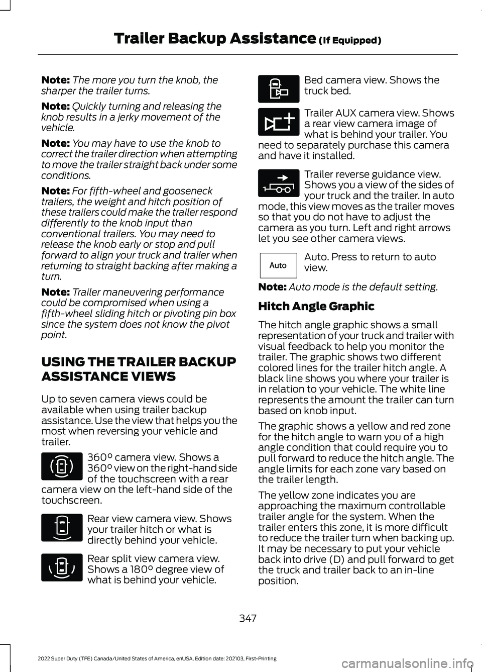
Up to seven camera views could be
available when using trailer backup
assistance. Use the view that helps you the
most when reversing your vehicle and
trailer. 360° camera view. Shows a
360° view on the right-hand side
of the touchscreen with a rear
camera view on the left-hand side of the
touchscreen. Rear view camera view. Shows
your trailer hitch or what is
directly behind your vehicle.
Rear split view camera view.
Shows a
180° degree view of
what is behind your vehicle. Bed camera view. Shows the
truck bed.
Trailer AUX camera view. Shows
a rear view camera image of
what is behind your trailer. You
need to separately purchase this camera
and have it installed. Trailer reverse guidance view.
Shows you a view of the sides of
your truck and the trailer. In auto
mode, this view moves as the trailer moves
so that you do not have to adjust the
camera as you turn. Left and right arrows
let you see other camera views. Auto. Press to return to auto
view.
Note: Auto mode is the default setting.
Hitch Angle Graphic
The hitch angle graphic shows a small
representation of your truck and trailer with
visual feedback to help you monitor the
trailer. The graphic shows two different
colored lines for the trailer hitch angle. A
black line shows you where your trailer is
in relation to your vehicle. The white line
represents the amount the trailer can turn
based on knob input.
The graphic shows a yellow and red zone
for the hitch angle to warn you of a high
angle condition that could require you to
pull forward to reduce the hitch angle. The
angle limits for each zone vary based on
the trailer length.
The yellow zone indicates you are
approaching the maximum controllable
trailer angle for the system. When the
trailer enters this zone, it is more difficult
to reduce the trailer turn when backing up.
It may be necessary to put your vehicle
back into drive (D) and pull forward to get
the truck and trailer back to an in-line
position.
347
2022 Super Duty (TFE) Canada/United States of America, enUSA, Edition date: 202103, First-Printing Trailer Backup Assistance
(If Equipped)E310996 E310967 E310974 E310995 E311776 E310965 E315644
Page 376 of 740

COLD WEATHER
PRECAUTIONS
The functional operation of some
components and systems can be affected
at temperatures below approximately
-13°F (-25°C).
BREAKING-IN
Your vehicle requires a break-in period. For
the first 1,000 mi (1,600 km), avoid driving
at high speeds, heavy braking, aggressive
shifting or using your vehicle to tow. During
this time, your vehicle may exhibit some
unusual driving characteristics.
DRIVING ECONOMICALLY
The following helps to improve fuel
consumption:
• Drive smoothly, accelerate gently and
anticipate the road ahead to avoid
heavy braking.
• Regularly check your tire pressures and
make sure that they are inflated to the
correct pressure.
• Follow the recommended maintenance
schedule and carry out the
recommended checks.
• Plan your journey and check the traffic
before you set off. It is more efficient
to combine errands into a single trip
whenever possible.
• Avoid idling the engine in cold weather
or for extended periods. Start the
engine only when you are ready to set
off.
• Do not carry unnecessary weight in your
vehicle as extra weight wastes fuel. •
Do not add unnecessary accessories
to the exterior of your vehicle, for
example running boards. If you use a
roof rack, remember to fold it down or
remove it when not in use.
• Do not shift into neutral when you are
braking or when your vehicle is slowing
down.
• Shut all windows when driving at high
speeds.
• Switch off all electric systems when
not in use, for example air conditioning.
Make sure that you unplug any
accessories from the auxiliary power
points when not in use.
DRIVING THROUGH SHALLOW
WATER WARNING:
Do not attempt to
cross a deep or flowing body of water.
Failure to follow this instruction could
result in the loss of control of your
vehicle, personal injury or death.
Note: Driving through standing water can
cause vehicle damage.
Note: Engine damage can occur if water
enters the air filter.
Before driving through standing water,
check the depth. Never drive through water
that is higher than the bottom of the wheel
hubs.
373
2022 Super Duty (TFE) Canada/United States of America, enUSA, Edition date: 202103, First-Printing Driving Hints
Page 379 of 740

SNOW PLOWING
PRECAUTIONS
WARNING: Modifying or adding
equipment to the front of your vehicle
could affect the performance of the
airbag system, increasing the risk of
injury. This includes the hood, bumper
system, frame, front body structure, tow
hooks, hood pins, push bar and
snowplows. WARNING:
Do not attempt to
service, repair, or modify the
supplementary restraint system or
associated components. Failure to
follow this instruction could result in
personal injury or death. WARNING:
All occupants of your
vehicle, including the driver, should
always properly wear their seatbelts,
even when an airbag supplemental
restraint system is provided. Failure to
properly wear your seatbelt could
seriously increase the risk of injury or
death. WARNING:
Do not spin the wheels
at over 34 mph (55 km/h). The tires may
fail and injure a passenger or bystander.
Note: Look for an alterer ’s label on your
vehicle from the snowplow installer
certifying that the installation meets all
applicable Federal Motor Vehicle Safety
Standards (FMVSS).
Note: Federal and some local regulations
require additional exterior lamps for
snowplow-equipped vehicles. Contact an
authorized dealer for additional information. Note:
Do not remove or defeat the tripping
mechanisms designed into the snow
removal equipment by its manufacturer.
Doing so could cause damage to your
vehicle and the snow removal equipment
as well as possible airbag deployment.
OPERATING YOUR VEHICLE
WITH A SNOWPLOW
Ford Motor Company recommends the
snowplow package if using your vehicle for
snow removal. Weight limits and
guidelines for selecting and installing the
snowplow are in the Ford Truck Body
Builders Layout Book. For additional
information, visit
www .f or dbb a s. c om/home .
A typical snowplow installation affects the
following:
• The total accessory reserve capacity,
which is the weight of
permanently-attached auxiliary
equipment, such as snowplow
frame-mounting hardware, that you
can add to the vehicle and satisfy Ford
Motor Company compliance
certification. This weight is on the lower
right-hand side of the vehicle's Safety
Compliance Certification Label and
applies to Ford Motor
Company-completed vehicles of
10,000 lb (4,536 kg)
gross vehicle
weight rating or less. Exceeding this
weight could require additional safety
certification responsibility for the
auxiliary equipment installer. See
Locating the Safety Compliance
Certification Labels
(page 312).
• Front gross axle weight rating. See
What Is the Gross Axle Weight
Rating
(page 312).
• Gross vehicle weight rating. See
What
Is the Gross Vehicle Weight Rating
(page
312).
376
2022 Super Duty (TFE) Canada/United States of America, enUSA, Edition date: 202103, First-Printing Snow Plowing
Page 380 of 740

•
Braking and steering.
• Front wheel toe. See the Ford
Workshop Manual.
• Headlight aim. See
Adjusting the
Headlamps (page 411).
• Tire air pressure. See Information on
the Tire Sidewall
(page 430).
Note: Do not exceed the front gross axle
weight rating or gross vehicle weight rating.
Note: Your vehicle may require rear ballast
weight for proper braking and steering.
Your vehicle has a driver and passenger
airbag supplemental restraint system. The
supplemental restraint system activates
in certain frontal and offset frontal
collisions when the vehicle sustains
sufficient longitudinal deceleration.
When operating your vehicle with a
snowplow:
• Do not exceed
45 mph (72 km/h).
• Your engine could run at a higher
temperature than normal.
•If you are driving more than
15 mi
(24 km) at temperatures above
freezing, angle the plow blade
either full left or full right to provide
maximum airflow to the radiator.
• If you are driving less than
15 mi
(24 km) at speeds up to 45 mph
(72 km/h) in cold weather, you do
not need to worry about blade
position to provide maximum
airflow.
• Shift to 4L when plowing in small areas
at speeds below
5 mph (8 km/h).
• Shift to
4H when plowing larger areas
or light snow at higher speeds above
5 mph (8 km/h)
. Do not exceed
15 mph (24 km/h).
• Do not shift the transmission from a
forward gear to reverse (R) until the
engine is at idle and the wheels have
stopped. Note:
Careless or high-speed driving when
snowplowing, which results in significant
vehicle decelerations, can deploy the airbag.
Such driving also increases the risk of
accidents.
Note: Drive your vehicle at least
500 mi
(800 km) before using your vehicle for
snowplowing.
Note: Follow the severe duty schedule for
engine oil and transmission fluid change
intervals. See
Special Operating
Conditions Scheduled Maintenance (page
631
).
377
2022 Super Duty (TFE) Canada/United States of America, enUSA, Edition date: 202103, First-Printing Snow Plowing
Page 385 of 740

AUTOMATIC CRASH SHUTOFF
PRECAUTIONS
WARNING: If your vehicle has been
involved in a crash, have the fuel system
checked. Failure to follow this instruction
could result in fire, personal injury or
death.
RE-ENABLING YOUR VEHICLE
1. Switch the ignition off.
2. Attempt to start your vehicle.
3. Switch the ignition off.
4. Attempt to start your vehicle.
Note: If your vehicle does not start after the
third attempt, have your vehicle checked as
soon as possible.
RECOVERY TOWING
ACCESSING THE FRONT TOWING
POINT WARNING: Using recovery hooks
is dangerous and should only be done by
a person familiar with proper vehicle
recovery safety practices. Improper use
of recovery hooks may cause hook failure
or separation from the vehicle and could
result in serious injury or death. WARNING:
Slowly remove the
slack from the recovery strap prior to
pulling. Failure to do so can introduce
significantly higher loads which can
cause the recovery hooks to break off, or
the recovery strap to fail which can cause
serious injury or death. WARNING:
Never link two straps
together with a clevis pin. These heavy
metal objects could become projectiles
if the strap breaks and can cause serious
injury or death.
Your vehicle has frame-mounted front
recovery hooks.
Note: Do not apply a load to the recovery
hooks that is greater than the gross vehicle
weight rating of your vehicle.
Before using recovery hooks:
• Make sure all attaching points are
secure and capable of withstanding
the applied load.
• Do not use chains, cables or tow straps
with metal hook ends.
• Only use recovery straps that have a
minimum breaking strength two to
three times the gross vehicle weight of
the stuck vehicle.
• Make sure the recovery strap is in good
condition and free of visible cuts, tears
or damage.
• Use a damper device such as a tarp,
heavy blanket or piece of carpet, and
place it over the recovery strap to help
absorb the energy in the event the
strap breaks.
• Make sure the stuck vehicle is not
loaded heavier than its gross vehicle
weight rating specified on the
certification label.
• Align the tow vehicle and stuck vehicle
in a straight line, within 10 degrees.
• Keep bystanders to the sides of the
vehicle, at a distance of at least twice
the length of the recovery strap. This
helps avoid injury from the hazard of a
recovery hook or strap breaking, or a
vehicle lurching into their path.
382
2022 Super Duty (TFE) Canada/United States of America, enUSA, Edition date: 202103, First-Printing Crash and Breakdown Information
Page 434 of 740

Information on P Type Tires
P215/65R15 95H is an example of
a tire size, load index and speed
rating. The definitions of these
items are listed below. (Note that
the tire size, load index and speed
rating for your vehicle may be
different from this example.)
A.
P: Indicates a tire, designated
by the Tire and Rim Association,
that may be used for service on
cars, sport utility vehicles,
minivans and light trucks. Note:
If
your tire size does not begin with
a letter this may mean it is
designated by either the European
Tire and Rim Technical
Organization or the Japan Tire
Manufacturing Association. B.
215:
Indicates the nominal
width of the tire in millimeters
from sidewall edge to sidewall
edge. In general, the larger the
number, the wider the tire.
C. 65:
Indicates the aspect ratio
which gives the tire's ratio of
height to width.
D. R:
Indicates a radial type tire.
E. 15:
Indicates the wheel or rim
diameter in inches. If you change
your wheel size, you will have to
purchase new tires to match the
new wheel diameter.
F. 95:
Indicates the tire's load
index. It is an index that relates to
how much weight a tire can carry.
You may find this information in
your owner ’s manual. If not,
contact a local tire dealer.
Note: You may not find this
information on all tires because it
is not required by federal law.
G. H:
Indicates the tire's speed
rating. The speed rating denotes
the speed at which a tire is
designed to be driven for extended
periods of time under a standard
condition of load and inflation
pressure. The tires on your vehicle
may operate at different
conditions for load and inflation
pressure. These speed ratings may
need to be adjusted for the
difference in conditions. The
ratings range from
81 mph
(130 km/h) to 186 mph
(299 km/h)
. These ratings are
listed in the following chart.
431
2022 Super Duty (TFE) Canada/United States of America, enUSA, Edition date: 202103, First-Printing Wheel and Tire InformationH
I
J
KL
M
A
B
CDEFGE142543
Page 438 of 740

C.
80: Indicates the aspect ratio
which gives the tire's ratio of
height to width. Numbers of 70 or
lower indicate a short sidewall.
D. D:
Indicates a diagonal type tire.
R:
Indicates a radial type tire.
E. 16:
Indicates the wheel or rim
diameter in inches. If you change
your wheel size, you will have to
purchase new tires to match the
new wheel diameter.
GLOSSARY OF TIRE
TERMINOLOGY
*
Tire label: A label showing the
original equipment tire sizes,
recommended inflation pressure
and the maximum weight the
vehicle can carry.
*
Tire Identification Number
(TIN): A number on the sidewall
of each tire providing information
about the tire brand and
manufacturing plant, tire size and
date of manufacture. Also referred
to as DOT code.
*
Inflation pressure: A measure
of the amount of air in a tire.
*
Standard load: A class of
P-metric or Metric tires designed
to carry a maximum load at set
pressure. For example: For
P-metric tires
35 psi (2.4 bar) and
for Metric tires 36 psi (2.5 bar).
Increasing the inflation pressure
beyond this pressure will not
increase the tire ’s load carrying
capability. *
Extra load: A class of P-metric
or Metric tires designed to carry a
heavier maximum load at
42 psi
(2.9 bar). Increasing the inflation
pressure beyond this pressure will
not increase the tire ’s load
carrying capability.
*
kPa: Kilopascal, a metric unit of
air pressure.
*
PSI: Pounds per square inch, a
standard unit of air pressure.
*
Cold tire pressure: The tire
pressure when the vehicle has
been stationary and out of direct
sunlight for an hour or more and
prior to the vehicle being driven for
1 mi (1.6 km)
.
*
Recommended inflation
pressure: The cold inflation
pressure found on the Safety
Compliance Certification Label
(affixed to either the door hinge
pillar, door-latch post, or the door
edge that meets the door-latch
post, next to the driver's seating
position), or Tire Label located on
the B-Pillar or the edge of the
driver door.
* B-pillar: The structural member
at the side of the vehicle behind
the front door.
*
Bead area of the tire: Area of
the tire next to the rim.
*
Sidewall of the tire: Area
between the bead area and the
tread.
435
2022 Super Duty (TFE) Canada/United States of America, enUSA, Edition date: 202103, First-Printing Wheel and Tire Information
Page 460 of 740

WARNING: To help prevent your
vehicle from moving when changing a
wheel, shift the transmission into park
(P), set the parking brake and use an
appropriate block or wheel chock to
secure the wheel diagonally opposite to
the wheel being changed. For example,
when changing the front left wheel,
place an appropriate block or wheel
chock on the right rear wheel. WARNING:
Always use the jack
provided as original equipment with your
vehicle. If using a jack other than the one
provided, make sure the jack capacity is
adequate for the vehicle weight,
including any vehicle cargo or
modifications. If you are unsure if the jack
capacity is adequate, contact the
authorized dealer. WARNING:
Failure to follow these
guidelines could result in an increased
risk of loss of vehicle control, injury or
death. WARNING:
Never place anything
between the vehicle jack and your
vehicle. WARNING:
Never place anything
between the vehicle jack and the ground. WARNING:
Park your vehicle so
that you do not obstruct the flow of
traffic or place yourself in any danger and
set up a warning triangle. WARNING:
The jack supplied with
this vehicle is only intended for changing
a flat tire in an emergency. Do not
attempt to do any other work on your
vehicle when it is supported by the jack,
as your vehicle could slip off the jack.
Failure to follow this instruction could
result in personal injury or death. WARNING:
Do not attempt to
change a tire on the side of the vehicle
close to moving traffic. Pull far enough
off the road to avoid the danger of being
hit when operating the jack or changing
the wheel. WARNING:
Only use the spare
wheel carrier to stow wheels provided
with your vehicle.
Note: Do not use impact tools or power
tools operating at over 200 RPM on the
spare wheel carrier winch, which may cause
it to malfunction and result in the wheel and
tire not being securely stowed.
Note: Passengers should not remain in the
vehicle when the vehicle is being jacked.
1. Park the vehicle on a level firm ground and activate the hazard flashers.
2. Apply the parking brake, place the transmission in park (P), switch the
engine off.
3. Block the wheel diagonally opposite the flat tire. For example, if the left
front tire is flat, block the right rear
wheel. 4. You can find the jack on the floor
behind the rear-most seat on the
passenger side. Turn the retainers
counterclockwise to remove the jack.
457
2022 Super Duty (TFE) Canada/United States of America, enUSA, Edition date: 202103, First-Printing Changing a Road WheelE175447