2022 FORD F-550 tailgate
[x] Cancel search: tailgatePage 321 of 740
INSTALLING AND REMOVING THE
PICKUP BED TIE-DOWN CLEATS
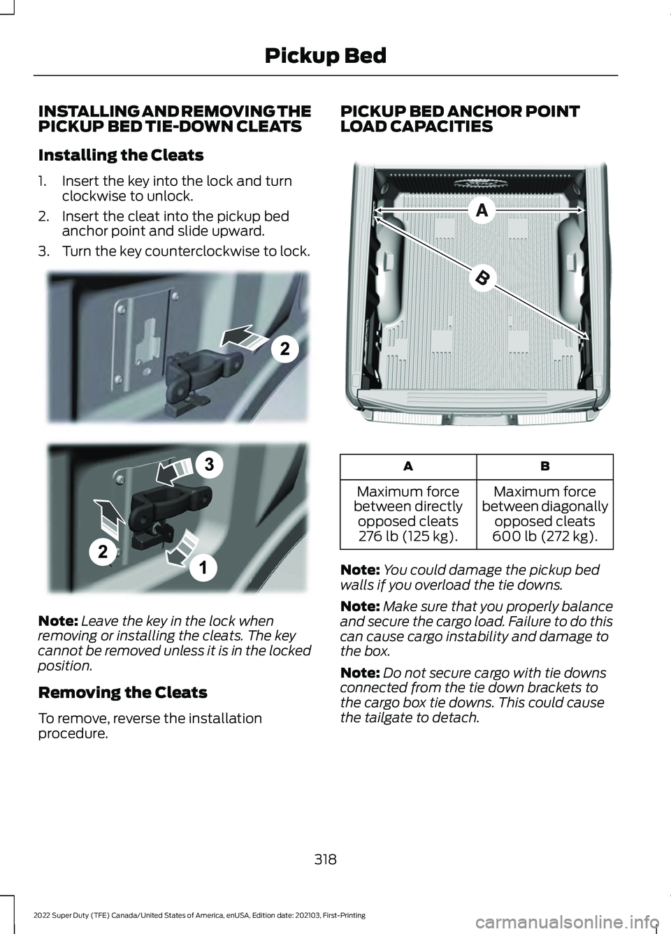
Installing the Cleats
1. Insert the key into the lock and turn
clockwise to unlock.
2. Insert the cleat into the pickup bed anchor point and slide upward.
3. Turn the key counterclockwise to lock. Note:
Leave the key in the lock when
removing or installing the cleats. The key
cannot be removed unless it is in the locked
position.
Removing the Cleats
To remove, reverse the installation
procedure. PICKUP BED ANCHOR POINT
LOAD CAPACITIES
B
A
Maximum force
between diagonally opposed cleats
600 lb (272 kg).
Maximum force
between directly opposed cleats276 lb (125 kg).
Note: You could damage the pickup bed
walls if you overload the tie downs.
Note: Make sure that you properly balance
and secure the cargo load. Failure to do this
can cause cargo instability and damage to
the box.
Note: Do not secure cargo with tie downs
connected from the tie down brackets to
the cargo box tie downs. This could cause
the tailgate to detach.
318
2022 Super Duty (TFE) Canada/United States of America, enUSA, Edition date: 202103, First-Printing Pickup BedE327575 E327576
Page 322 of 740
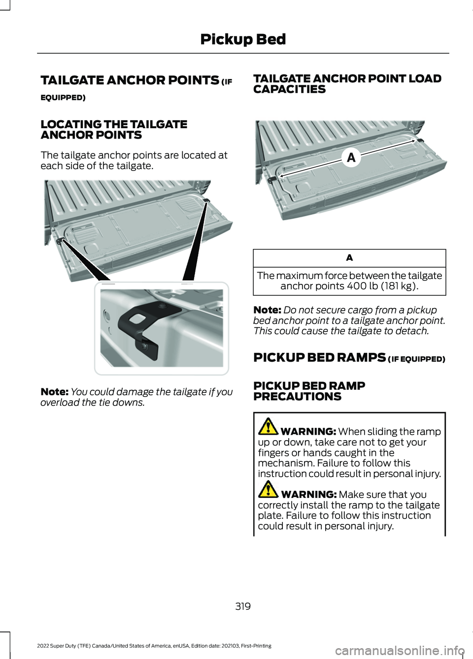
TAILGATE ANCHOR POINTS (IF
EQUIPPED)
LOCATING THE TAILGATE
ANCHOR POINTS
The tailgate anchor points are located at
each side of the tailgate. Note:
You could damage the tailgate if you
overload the tie downs. TAILGATE ANCHOR POINT LOAD
CAPACITIES A
The maximum force between the tailgate anchor points
400 lb (181 kg).
Note: Do not secure cargo from a pickup
bed anchor point to a tailgate anchor point.
This could cause the tailgate to detach.
PICKUP BED RAMPS (IF EQUIPPED)
PICKUP BED RAMP
PRECAUTIONS WARNING:
When sliding the ramp
up or down, take care not to get your
fingers or hands caught in the
mechanism. Failure to follow this
instruction could result in personal injury. WARNING:
Make sure that you
correctly install the ramp to the tailgate
plate. Failure to follow this instruction
could result in personal injury.
319
2022 Super Duty (TFE) Canada/United States of America, enUSA, Edition date: 202103, First-Printing Pickup BedE327594 E327790
Page 323 of 740

WARNING: Do not step or sit on
the ramp when it is in the stowed
position. Failure to follow this instruction
could result in personal injury. WARNING:
Only install the ramp
within the prescribed ramp angles.
Failure to follow this instruction could
result in personal injury.
Note: Each pickup bed ramp has a
maximum capacity of
400 lb (181.4 kg).
Note: Verify the ramp is on stable ground
before usage.
Note: For loading and unloading
equipment, your ramp should be set
between 10 degrees upward and 26 degrees
downward to avoid damage to the ramp
claw and tailgate plate.
Note: When using your vehicle for off-road
operation, remove the bed ramps from the
vehicle and store them in a safe location
away from your vehicle.
INSTALLING AND REMOVING THE
PICKUP BED RAMP HOLDER
Installing the Ramp Holder 1. Hook the top of the ramp holder over
the mounting plate and rotate the
ramp holder into position. 2. Slide the ramp holder studs upwards
into the installed position.
3. Tighten the ramp holder nut.
Note: The nut should be on the upper stud.
Removing the Ramp Holder
Remove in the reverse order.
INSTALLING AND REMOVING THE
PICKUP BED RAMPS
Note: You cannot use the pickup bed ramps
with the tailgate work surface or tailgate
step.
Installing the Bed Ramp
1. Remove the front and rear cables. 2.
Open the cam lever arms and unscrew
the cam bolts.
320
2022 Super Duty (TFE) Canada/United States of America, enUSA, Edition date: 202103, First-Printing Pickup BedE194387 E194388 E194380
Page 324 of 740
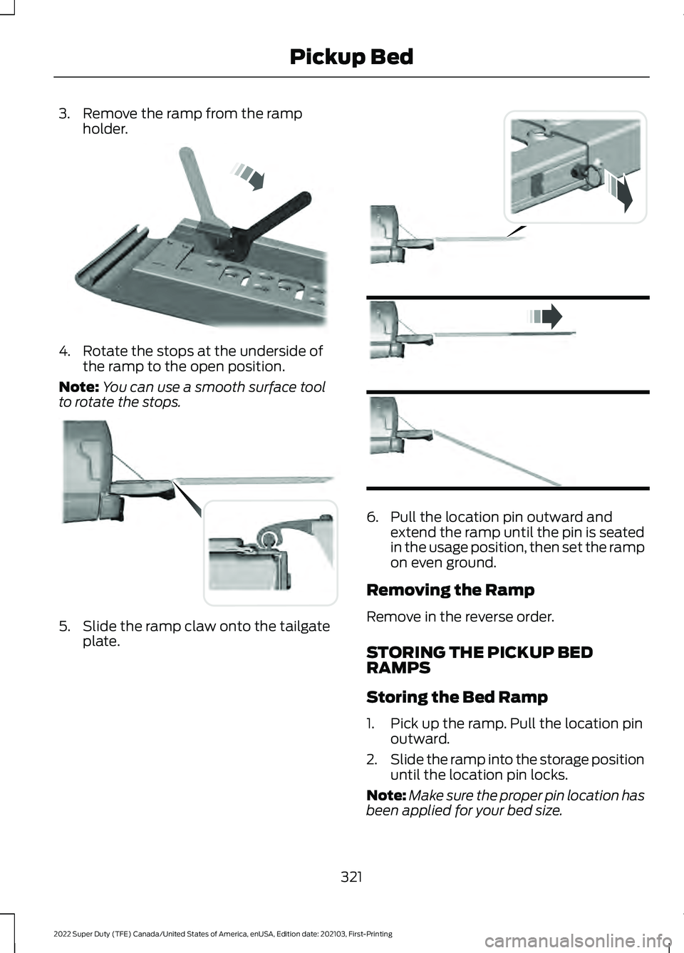
3. Remove the ramp from the ramp
holder. 4. Rotate the stops at the underside of
the ramp to the open position.
Note: You can use a smooth surface tool
to rotate the stops. 5. Slide the ramp claw onto the tailgate
plate. 6. Pull the location pin outward and
extend the ramp until the pin is seated
in the usage position, then set the ramp
on even ground.
Removing the Ramp
Remove in the reverse order.
STORING THE PICKUP BED
RAMPS
Storing the Bed Ramp
1. Pick up the ramp. Pull the location pin outward.
2. Slide the ramp into the storage position
until the location pin locks.
Note: Make sure the proper pin location has
been applied for your bed size.
321
2022 Super Duty (TFE) Canada/United States of America, enUSA, Edition date: 202103, First-Printing Pickup BedE211150 E194382 E194383
Page 325 of 740
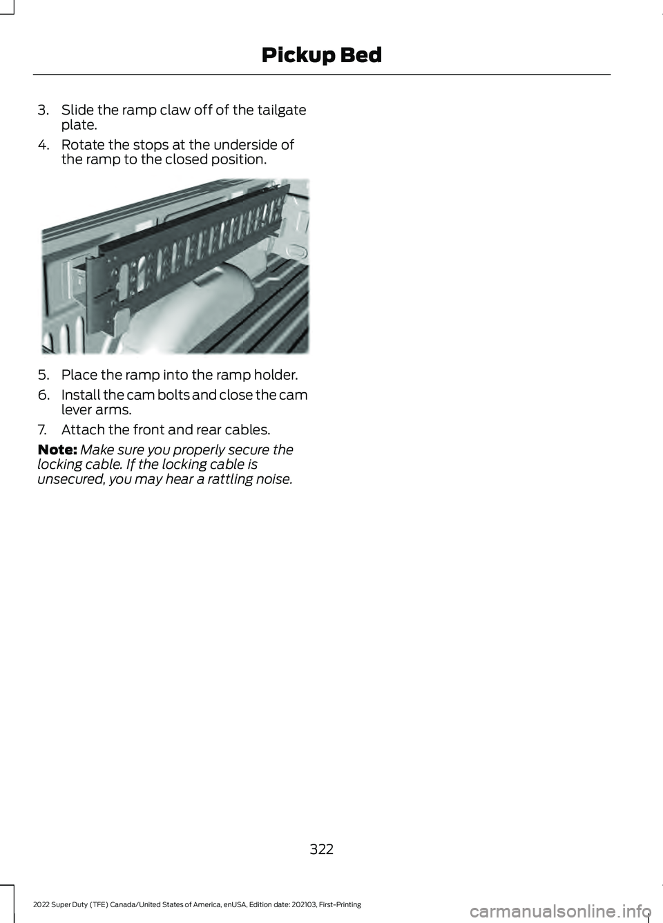
3. Slide the ramp claw off of the tailgate
plate.
4. Rotate the stops at the underside of the ramp to the closed position. 5. Place the ramp into the ramp holder.
6.
Install the cam bolts and close the cam
lever arms.
7. Attach the front and rear cables.
Note: Make sure you properly secure the
locking cable. If the locking cable is
unsecured, you may hear a rattling noise.
322
2022 Super Duty (TFE) Canada/United States of America, enUSA, Edition date: 202103, First-Printing Pickup BedE194391
Page 345 of 740
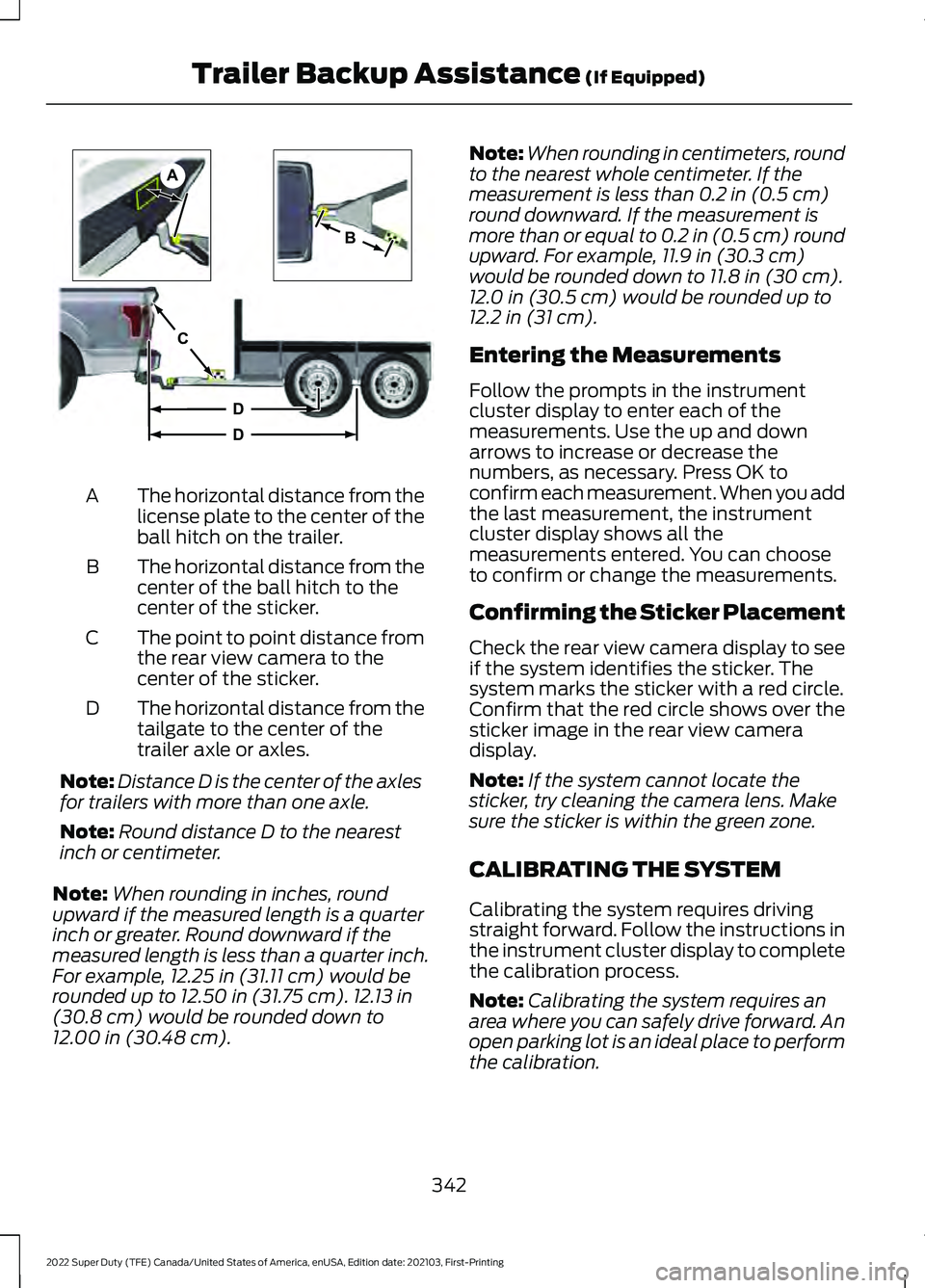
The horizontal distance from the
license plate to the center of the
ball hitch on the trailer.
A
The horizontal distance from the
center of the ball hitch to the
center of the sticker.
B
The point to point distance from
the rear view camera to the
center of the sticker.
C
The horizontal distance from the
tailgate to the center of the
trailer axle or axles.
D
Note: Distance D is the center of the axles
for trailers with more than one axle.
Note: Round distance D to the nearest
inch or centimeter.
Note: When rounding in inches, round
upward if the measured length is a quarter
inch or greater. Round downward if the
measured length is less than a quarter inch.
For example, 12.25 in (31.11 cm) would be
rounded up to 12.50 in (31.75 cm). 12.13 in
(30.8 cm) would be rounded down to
12.00 in (30.48 cm). Note:
When rounding in centimeters, round
to the nearest whole centimeter. If the
measurement is less than
0.2 in (0.5 cm)
round downward. If the measurement is
more than or equal to 0.2 in (0.5 cm) round
upward. For example, 11.9 in (30.3 cm)
would be rounded down to
11.8 in (30 cm).
12.0 in (30.5 cm) would be rounded up to
12.2 in (31 cm).
Entering the Measurements
Follow the prompts in the instrument
cluster display to enter each of the
measurements. Use the up and down
arrows to increase or decrease the
numbers, as necessary. Press OK to
confirm each measurement. When you add
the last measurement, the instrument
cluster display shows all the
measurements entered. You can choose
to confirm or change the measurements.
Confirming the Sticker Placement
Check the rear view camera display to see
if the system identifies the sticker. The
system marks the sticker with a red circle.
Confirm that the red circle shows over the
sticker image in the rear view camera
display.
Note: If the system cannot locate the
sticker, try cleaning the camera lens. Make
sure the sticker is within the green zone.
CALIBRATING THE SYSTEM
Calibrating the system requires driving
straight forward. Follow the instructions in
the instrument cluster display to complete
the calibration process.
Note: Calibrating the system requires an
area where you can safely drive forward. An
open parking lot is an ideal place to perform
the calibration.
342
2022 Super Duty (TFE) Canada/United States of America, enUSA, Edition date: 202103, First-Printing Trailer Backup Assistance
(If Equipped)A
B
C
D
DE209806
Page 355 of 740
TRAILER BACKUP ASSISTANCE
– FREQUENTLY ASKED
QUESTIONS
What does it mean if Measurement A
has reached its maximum or minimum
value?
The system is designed to work with
drawbars that have a license plate to
hitch ball center measurement of
9–20 in (23–52 cm) when installed.
Do not attempt to use drawbars that
have a length outside this range as the
system performance degrades and
could cause improper system function.
Make sure that the measurement
being made is the horizontal distance
only from the license plate to the hitch
ball center. A straight line distance
that includes any vertical rise or drop
increases the measurement and
makes it inaccurate. Inaccurate
measurements degrade system
performance and could cause
improper system function. See
Applying the Trailer Reversing Aid
Sticker
(page 341).
What does it mean if Measurement B
has reached its maximum or minimum
value? Make sure that the sticker is properly
placed. Stickers placed outside the
allowed zone adversely affects the
system performance and could cause
improper feature function. Make sure
that the measurement being made is
the horizontal distance only from
center of the sticker to the hitch ball
center. A straight line distance that
includes any vertical rise or drop
increases the measurement and
causes an inaccurate value to be
entered into the system. See
Applying the Trailer Reversing Aid
Sticker
(page 341). What does it mean if Measurement C
has reached its maximum or minimum
value?
Make sure you follow the sticker
placement instructions. Stickers
placed outside the allowed zone
adversely affect the system
performance and could cause
improper feature function. If you have
met all the criteria for sticker
placement and you see this message,
the sticker is either too far below or too
close to the camera to properly
recognize the sticker. For the system
to correctly operate, lower the sticker
height if you receive the minimum
warning or raise the sticker height if
you receive the maximum warning.
Only one sticker can be placed on the
trailer for correct system function. The
previous sticker must be removed or
covered so only one sticker is visible
to the camera. Measurement B and C
must be measured again if a new
sticker is placed on the trailer. See
Applying the Trailer Reversing Aid
Sticker
(page 341).
What does it mean if Measurement D
has reached its maximum or minimum
value? Make sure that the measurement
being made is the horizontal distance
only from tailgate to the center of the
single axle or the center of all the axles
on the trailer. The system does not
support trailer lengths outside the
range allowed by the information
display. See
Applying the Trailer
Reversing Aid Sticker (page 341).
352
2022 Super Duty (TFE) Canada/United States of America, enUSA, Edition date: 202103, First-Printing Trailer Backup Assistance
(If Equipped)
Page 362 of 740

APPLYING THE TRAILER
REVERSE AID STICKER
Placing the Sticker
Place the sticker in an area visible by the
rear view camera. The entire sticker must
be within 7
– 20 in (17 –51 cm) from the
center of the hitch ball, as shown in the
following illustration. Use the supplied sticker placement card,
a tape measure and pen to carefully mark
the area to attach the sticker. The sticker
is in the back cover pocket of your quick
start guide. Make sure the entire sticker is
within the green zone between the two
arcs or distance markers on the diagram,
and is also visible in the rear view camera
display.
Once you have found the correct location,
place the sticker.
Note:
Make sure nothing can obstruct the
rear view camera's view of the sticker such
as a jack handle or wiring.
Note: Position the sticker on a flat, dry and
clean horizontal surface. For best results,
apply the sticker when temperatures are
above
32°F (0°C).
Note: Do not move stickers after placing
them. Do not re-use any stickers if removed.
Note: See your authorized dealer to
purchase additional stickers. Taking the Measurements
After you place the sticker on your trailer,
you must take some measurements.
The measurement card requires recording
four distances: A, B, C and D. Record the
trailer name for these measurements.
Note:
Use consistent metric or imperial
units as required by your country or vehicle.
Note: The system requires accurate
measurements to properly operate. The horizontal distance from the
license plate to the center of the
ball hitch on the trailer.
A
The horizontal distance from the
center of the ball hitch to the
center of the sticker.
B
The point to point distance from
the rear view camera to the
center of the sticker.
C
The horizontal distance from the
tailgate to the center of the
trailer axle or axles.
D
Note: Distance D is the center of the axles
for trailers with more than one axle.
Note: Round distance D to the nearest
inch or centimeter.
359
2022 Super Duty (TFE) Canada/United States of America, enUSA, Edition date: 202103, First-Printing Trailer Reverse Guidance
(If Equipped)E310619 A
B
C
D
DE209806