2022 CHRYSLER PACIFICA Battery
[x] Cancel search: BatteryPage 308 of 384

306IN CASE OF EMERGENCY
TOWING A DISABLED VEHICLE
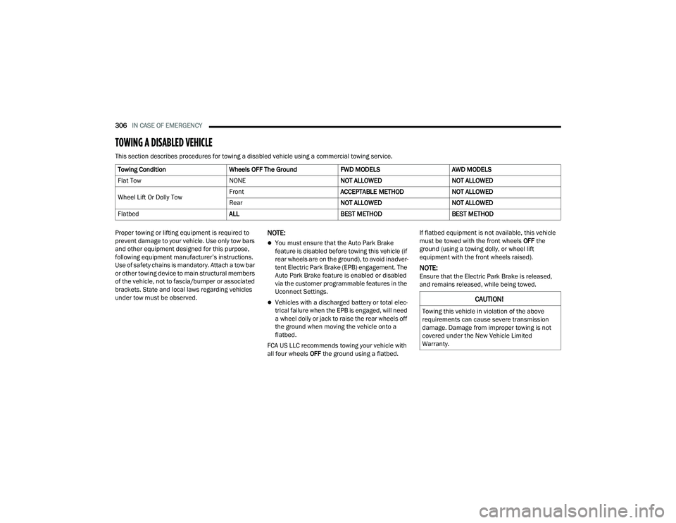
This section describes procedures for towing a disabled vehicle using a commercial towing service.
Proper towing or lifting equipment is required to
prevent damage to your vehicle. Use only tow bars
and other equipment designed for this purpose,
following equipment manufacturer’s instructions.
Use of safety chains is mandatory. Attach a tow bar
or other towing device to main structural members
of the vehicle, not to fascia/bumper or associated
brackets. State and local laws regarding vehicles
under tow must be observed.
NOTE:
You must ensure that the Auto Park Brake
feature is disabled before towing this vehicle (if
rear wheels are on the ground), to avoid inadver -
tent Electric Park Brake (EPB) engagement. The
Auto Park Brake feature is enabled or disabled
via the customer programmable features in the
Uconnect Settings.
Vehicles with a discharged battery or total elec -
trical failure when the EPB is engaged, will need
a wheel dolly or jack to raise the rear wheels off
the ground when moving the vehicle onto a
flatbed.
FCA US LLC recommends towing your vehicle with
all four wheels OFF the ground using a flatbed. If flatbed equipment is not available, this vehicle
must be towed with the front wheels
OFF the
ground (using a towing dolly, or wheel lift
equipment with the front wheels raised).
NOTE:Ensure that the Electric Park Brake is released,
and remains released, while being towed.
Towing Condition
Wheels OFF The GroundFWD MODELSAWD MODELS
Flat Tow NONENOT ALLOWEDNOT ALLOWED
Wheel Lift Or Dolly Tow Front
ACCEPTABLE METHODNOT ALLOWED
Rear NOT ALLOWEDNOT ALLOWED
Flatbed ALLBEST METHODBEST METHOD
CAUTION!
Towing this vehicle in violation of the above
requirements can cause severe transmission
damage. Damage from improper towing is not
covered under the New Vehicle Limited
Warranty.
22_RUP_OM_EN_USC_t.book Page 306
Page 309 of 384

IN CASE OF EMERGENCY307
Vehicle Recovery Tow Points
Your vehicle is equipped with Vehicle Recovery
Points that can be used to recover a disabled
vehicle, located on the underbody of the vehicle.
NOTE:
Ensure that the towing service tow hooks are
properly seated and secured in the attachment
points.
This recovery tow feature should be used by a
trained professional only.
Use approved receptacle location to free the
disabled vehicle from its environment.
Front Recovery Points
If you must use the accessories (wipers,
defrosters, etc.) while being towed, the ignition
must be in the ON/RUN mode, not the ACC mode.
NOTE:The Safehold feature will engage the Electric Park
Brake whenever the driver's door is opened (if the
ignition is ON, transmission is not in PARK, and
brake pedal is released). If you are towing this
vehicle with the ignition in the ON/RUN mode, you
must manually disable the Electric Park Brake
each time the driver's door is opened, by pressing
the brake pedal and then releasing the EPB.
If the key fob is unavailable or the vehicle's battery
is discharged, detailed instructions on shifting the
transmission out of PARK in order to move the
vehicle Ú
page 304.
CAUTION!
Recovery feature:
Is to be used by a professional ONLY.
Is used only to provide recovery of the vehicle.
Is NOT to be used to recover secondary
vehicle.
Is NOT to be used for transporting the vehicle
over the road, i.e. “Flat Towing”.
Is to be used by a professional ONLY.
Is used only to provide recovery of the vehicle.
Is NOT to be used to recover secondary
vehicle.
Is NOT to be used for transporting the vehicle
over the road, i.e. “Flat Towing”.
Recovery load should:
Be applied at constant speed.
Be applied parallel to the center line of the
length of the vehicle.
Not be an abrupt acceleration.
Be applied at constant speed.
Be applied parallel to the center line of the
length of the vehicle.
Not be an abrupt acceleration.
CAUTION!
Do not use sling-type equipment when towing.
Vehicle damage may occur.
When securing the vehicle to a flatbed truck,
do not attach to front or rear suspension
components. Damage to your vehicle may
result from improper towing.
Ensure that the Electric Park Brake is
released, and remains released, while being
towed.
7
22_RUP_OM_EN_USC_t.book Page 307
Page 312 of 384

310SERVICING AND MAINTENANCE
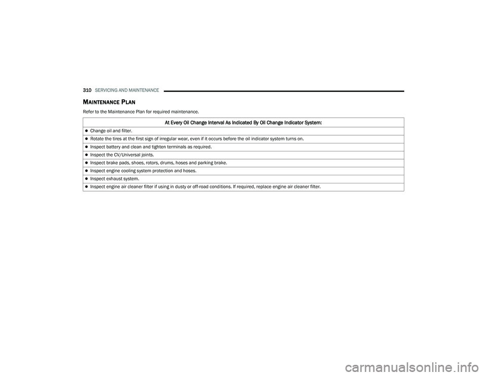
MAINTENANCE PLAN
Refer to the Maintenance Plan for required maintenance.
At Every Oil Change Interval As Indicated By Oil Change Indicator System:
Change oil and filter.
Rotate the tires at the first sign of irregular wear, even if it occurs before the oil indicator system turns on.
Inspect battery and clean and tighten terminals as required.
Inspect the CV/Universal joints.
Inspect brake pads, shoes, rotors, drums, hoses and parking brake.
Inspect engine cooling system protection and hoses.
Inspect exhaust system.
Inspect engine air cleaner filter if using in dusty or off-road conditions. If required, replace engine air cleaner filter.
22_RUP_OM_EN_USC_t.book Page 310
Page 315 of 384

SERVICING AND MAINTENANCE313
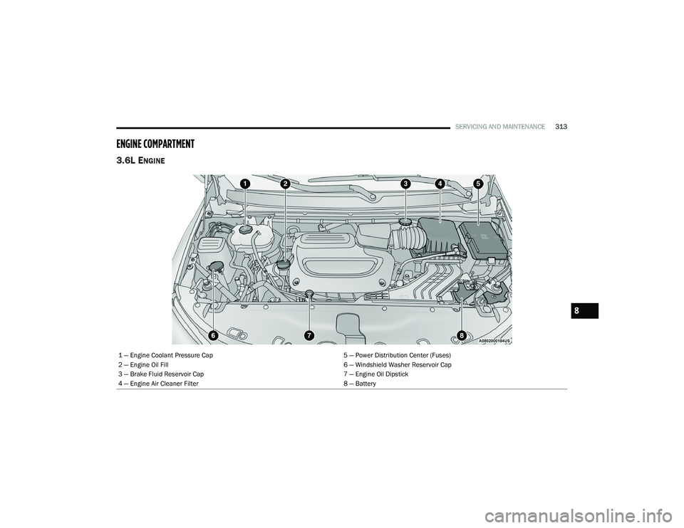
ENGINE COMPARTMENT
3.6L ENGINE
1 — Engine Coolant Pressure Cap 5 — Power Distribution Center (Fuses)
2 — Engine Oil Fill 6 — Windshield Washer Reservoir Cap
3 — Brake Fluid Reservoir Cap 7 — Engine Oil Dipstick
4 — Engine Air Cleaner Filter 8 — Battery
8
22_RUP_OM_EN_USC_t.book Page 313
Page 316 of 384

314SERVICING AND MAINTENANCE
(Continued)
CHECKING OIL LEVEL
To ensure proper engine lubrication, the engine oil
must be maintained at the correct level. Check the
oil level at regular intervals, such as every fuel
stop. The best time to check the engine oil level is
about five minutes after a fully warmed up engine
is shut off.
Checking the oil while the vehicle is on level ground
will improve the accuracy of the oil level readings.
There are four possible dipstick types:
Crosshatched zone.
Crosshatched zone marked SAFE.
Crosshatched zone marked with MIN at the low
end of the range and MAX at the high end of the
range.
Crosshatched zone marked with dimples at the
MIN and the MAX ends of the range.
NOTE:Always maintain the oil level within the crosshatch
markings on the dipstick.
Adding 1 quart (1.0 liter) of oil when the reading is
at the low end of the dipstick range will raise the oil
level to the high end of the range marking.
ADDING WASHER FLUID
Windshield Washer Fluid Cap
The fluid reservoir is located in the front of the
engine compartment. Be sure to check the fluid
level in the reservoir at regular intervals. Fill the
reservoir with windshield washer solvent (not
radiator antifreeze) and operate the system for a
few seconds to flush out the residual washer fluid.
When refilling the washer fluid reservoir, take
some washer fluid, apply it to a cloth or towel, and
wipe clean the wiper blades; this will help blade
performance. To prevent freeze-up of your windshield washer
system in cold weather, select a solution or mixture
that meets or exceeds the temperature range of
your climate. This rating information can be found
on most washer fluid containers.
MAINTENANCE-FREE BATTERY
Your vehicle is equipped with a maintenance-free
battery. You will never have to add water, and
periodic maintenance is not required.
CAUTION!
Overfilling or underfilling the crankcase will
cause aeration or loss of oil pressure. This could
damage your engine.
WARNING!
Commercially available windshield washer
solvents are flammable. They could ignite and
burn you. Care must be exercised when filling or
working around the washer solution.
WARNING!
Battery fluid is a corrosive acid solution and
can burn or even blind you. Do not allow
battery fluid to contact your eyes, skin, or
clothing. Do not lean over a battery when
attaching clamps. If acid splashes in eyes or
on skin, flush the area immediately with large
amounts of water Ú
page 300.
22_RUP_OM_EN_USC_t.book Page 314
Page 317 of 384

SERVICING AND MAINTENANCE315
PRESSURE WASHING
Cleaning the engine compartment with a high
pressure washer is not recommended.
VEHICLE MAINTENANCE
An authorized dealer has the qualified service
personnel, special tools, and equipment to
perform all service operations in an expert
manner. Service Manuals are available which
include detailed service information for your
vehicle. Refer to these Service Manuals before
attempting any procedure yourself.
NOTE:Intentional tampering with emissions control
systems may void your warranty and could result in
civil penalties being assessed against you.
ENGINE OIL
Engine Oil Selection
Use only the manufacturer's recommended fluids
Úpage 365.
Battery gas is flammable and explosive. Keep
flame or sparks away from the battery. Do not
use a booster battery or any other booster
source with an output greater than 12 Volts.
Do not allow cable clamps to touch each
other.
Battery posts, terminals, and related accesso -
ries contain lead and lead compounds. Wash
hands after handling.
CAUTION!
It is essential when replacing the cables on
the battery that the positive cable is attached
to the positive post and the negative cable is
attached to the negative post. Battery posts
are marked positive (+) and negative (-) and
are identified on the battery case. Cable
clamps should be tight on the terminal posts
and free of corrosion.
If a “fast charger” is used while the battery is
in the vehicle, disconnect both vehicle battery
cables before connecting the charger to the
battery. Do not use a “fast charger” to provide
starting voltage.
WARNING!
CAUTION!
Precautions have been taken to safeguard all
parts and connections however, the pressures
generated by these machines is such that
complete protection against water ingress
cannot be guaranteed.
WARNING!
You can be badly injured working on or around a
motor vehicle. Only do service work for which
you have the knowledge and the proper
equipment. If you have any doubt about your
ability to perform a service job, take your vehicle
to a competent mechanic.
8
22_RUP_OM_EN_USC_t.book Page 315
Page 331 of 384

SERVICING AND MAINTENANCE329
FUSES
General Information
The fuses protect electrical systems against
excessive current. When a device does not work, you must check the
fuse element inside the blade fuse for a break/
melt.
Also, please be aware that using power outlets for
extended periods of time with the engine off may
result in vehicle battery discharge.
Blade Fuses
Underhood Fuses
The Power Distribution Center (PDC) is located in
the engine compartment near the battery. This
center contains cartridge fuses, mini-fuses,
micro-fuses, circuit breakers and relays. A label
that identifies each component is printed on the
inside of the cover.
Before any procedure is done on the PDC, make
sure engine is turned off.
Remove the cover by unlatching the two locks
located at each side of the PDC cover, avoid using
screwdrivers or any other tool to remove the cover,
since they may apply excessive force and result in
a broken/damaged part.
After service is done, secure the cover with its two
locks.
NOTE:The function and amperage of the following fuses
are different, depending on vehicle trim level and
content.
WARNING!
When replacing a blown fuse, always use an
appropriate replacement fuse with the same
amp rating as the original fuse. Never replace
a fuse with another fuse of higher amp rating.
Never replace a blown fuse with metal wires or
any other material. Do not place a fuse inside
a circuit breaker cavity or vice versa. Failure to
use proper fuses may result in serious
personal injury, fire and/or property damage.
Before replacing a fuse, make sure that the
ignition is off and that all the other services
are switched off and/or disengaged.
If the replaced fuse blows again, contact an
authorized dealer.
If a general protection fuse for safety systems
(air bag system, braking system), power unit
systems (engine system, transmission
system) or steering system blows, contact an
authorized dealer.
1 — Fuse Element
2 — Blade Fuse with a good/functional fuse
element
3 — Blade fuse with a bad/not functional fuse
element (blown fuse)CAUTION!
When installing the power distribution center
cover, it is important to ensure the cover is
properly positioned and fully latched. Failure to
do so may allow water to get into the power
distribution center and possibly result in an
electrical system failure.8
22_RUP_OM_EN_USC_t.book Page 329
Page 332 of 384

330SERVICING AND MAINTENANCE
Power Distribution Center Location
Cavity Cartridge Fuse Blade FuseDescription
*If Equipped
F06 ––Not Populated
F07 –25 Amp ClearIgnition Coil / Fuel Injector
F08 ––Not Populated
F09 –25 Amp ClearAmplifier / Active Noise Control *
F10 ––Not Populated
F11 ––Not Populated
F12 –5 Amp TanBattery Sensor (IBS)
F13 –10 Amp Red ECM (S) *
F14 –10 Amp Red ECM
22_RUP_OM_EN_USC_t.book Page 330