2022 CHRYSLER PACIFICA Drive mode
[x] Cancel search: Drive modePage 84 of 384

82GETTING TO KNOW YOUR VEHICLE
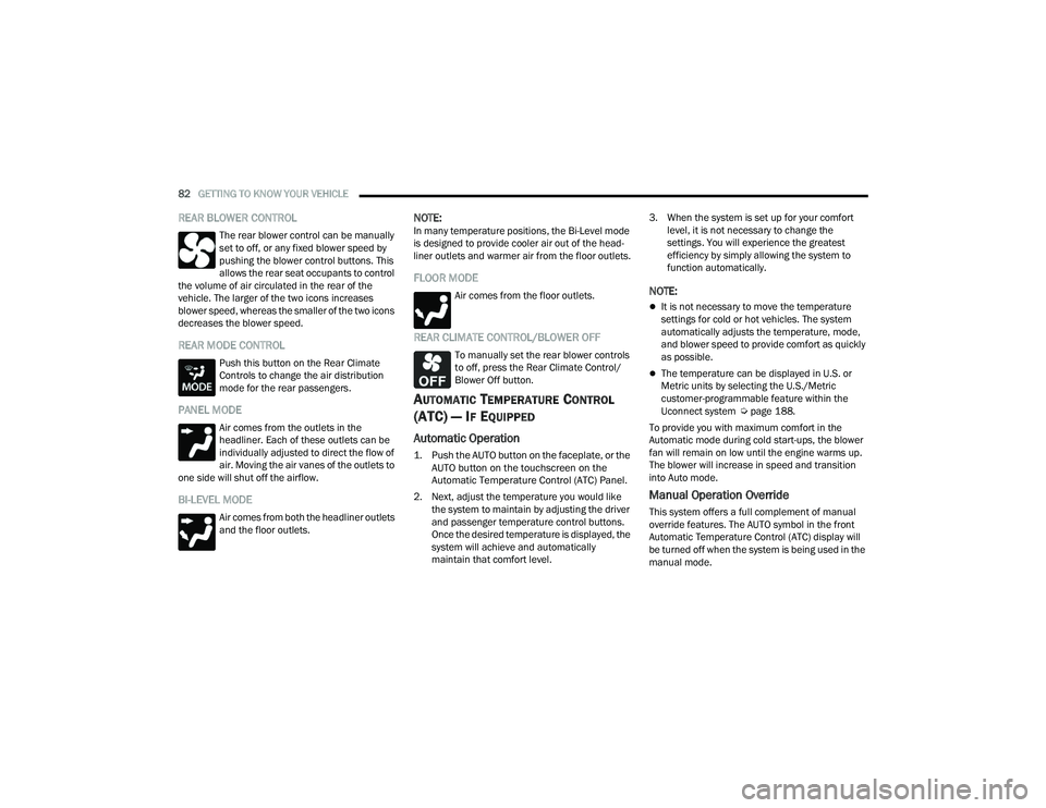
REAR BLOWER CONTROL
The rear blower control can be manually
set to off, or any fixed blower speed by
pushing the blower control buttons. This
allows the rear seat occupants to control
the volume of air circulated in the rear of the
vehicle. The larger of the two icons increases
blower speed, whereas the smaller of the two icons
decreases the blower speed.
REAR MODE CONTROL
Push this button on the Rear Climate
Controls to change the air distribution
mode for the rear passengers.
PANEL MODE
Air comes from the outlets in the
headliner. Each of these outlets can be
individually adjusted to direct the flow of
air. Moving the air vanes of the outlets to
one side will shut off the airflow.
BI-LEVEL MODE
Air comes from both the headliner outlets
and the floor outlets.
NOTE:In many temperature positions, the Bi-Level mode
is designed to provide cooler air out of the head -
liner outlets and warmer air from the floor outlets.
FLOOR MODE
Air comes from the floor outlets.
REAR CLIMATE CONTROL/BLOWER OFF
To manually set the rear blower controls
to off, press the Rear Climate Control/
Blower Off button.
AUTOMATIC TEMPERATURE CONTROL
(ATC) — I
F EQUIPPED
Automatic Operation
1. Push the AUTO button on the faceplate, or the
AUTO button on the touchscreen on the
Automatic Temperature Control (ATC) Panel.
2. Next, adjust the temperature you would like the system to maintain by adjusting the driver
and passenger temperature control buttons.
Once the desired temperature is displayed, the
system will achieve and automatically
maintain that comfort level. 3. When the system is set up for your comfort
level, it is not necessary to change the
settings. You will experience the greatest
efficiency by simply allowing the system to
function automatically.
NOTE:
It is not necessary to move the temperature
settings for cold or hot vehicles. The system
automatically adjusts the temperature, mode,
and blower speed to provide comfort as quickly
as possible.
The temperature can be displayed in U.S. or
Metric units by selecting the U.S./Metric
customer-programmable feature within the
Uconnect system Ú page 188.
To provide you with maximum comfort in the
Automatic mode during cold start-ups, the blower
fan will remain on low until the engine warms up.
The blower will increase in speed and transition
into Auto mode.
Manual Operation Override
This system offers a full complement of manual
override features. The AUTO symbol in the front
Automatic Temperature Control (ATC) display will
be turned off when the system is being used in the
manual mode.
22_RUP_OM_EN_USC_t.book Page 82
Page 85 of 384

GETTING TO KNOW YOUR VEHICLE83
CLIMATE VOICE COMMANDS
Adjust vehicle temperatures hands-free and keep
everyone comfortable while you keep moving
ahead. (If vehicle is equipped with climate control.)
Push the VR button on the steering wheel. After the
beep, say one of the following commands:
“Set driver temperature to 70 degrees ”
“Set passenger temperature to 70 degrees ”
Did you know : Voice Command for Climate may only
be used to adjust the interior temperature of your
vehicle. Voice Command will not work to adjust the
heated seats or steering wheel if equipped.
OPERATING TIPS
Refer to the chart at the end of this section for
suggested control settings for various weather
conditions.
Summer Operation
The engine cooling system must be protected with
a high-quality antifreeze coolant to provide proper
corrosion protection and to protect against engine
overheating. OAT coolant (conforming to
MS.90032) is recommended.
Winter Operation
To ensure the best possible heater and defroster
performance, make sure the engine cooling
system is functioning properly and the proper amount, type, and concentration of coolant is
used. Use of the Air Recirculation mode during
Winter months is not recommended, because it
may cause window fogging.
Vacation/Storage
For information on maintaining the Climate Control
system when the vehicle is being stored for an
extended period of time, see Ú
page 357.
Window Fogging
Vehicle windows tend to fog on the inside in mild,
rainy, and/or humid weather. To clear the
windows, select Defrost or Mix mode and increase
the front blower speed. Do not use the
Recirculation mode without A/C for long periods,
as fogging may occur.
Outside Air Intake
Make sure the air intake, located directly in front of
the windshield, is free of obstructions, such as
leaves. Leaves collected in the air intake may
reduce airflow, and if they enter the air distribution
box, they could plug the water drains. In Winter
months, make sure the air intake is clear of ice,
slush, and snow.
Cabin Air Filter
The Climate Control system filters out dust and
pollen from the air. Contact an authorized dealer to
service your cabin air filter, and to have it replaced
when needed.
Stop/Start System — If Equipped
While in an Autostop, the Climate Control system
may automatically adjust airflow to maintain cabin
comfort. Customer settings will be maintained
upon return to an engine running condition.
Operating Tips Chart
WEATHER CONTROL SETTINGS
Hot Weather
And Vehicle Interior Is Very Hot Set the mode control to
(Panel Mode), (A/C) on, and blower on high. Roll down the
windows for a minute to flush out the hot air. Adjust the controls as needed to achieve comfort.
Warm
Weather Turn (A/C) on and set the
mode control to (Panel Mode).
Cool Sunny Operate in (Bi-Level Mode).
Cool &
Humid
Conditions Set the mode control to (Floor
Mode) and turn (A/C) on to keep windows clear.
Cold
Weather Set the mode control to (Floor
Mode). If windshield fogging
starts to occur, move the control
to (Mix Mode).
2
22_RUP_OM_EN_USC_t.book Page 83
Page 99 of 384

GETTING TO KNOW YOUR VEHICLE97
LIFTGATE
TO UNLOCK/OPEN THE LIFTGATE
The liftgate may be released in several ways:
Key fob
Liftgate Release Handle
Button on overhead console
Push the liftgate button on the key fob twice within
five seconds to release the liftgate.
The key fob and the overhead console button will
release the liftgate when the liftgate is locked. The
outside handle requires the liftgate to be unlocked.
If the vehicle is equipped with Passive Entry,
pulling the electronic liftgate release handle will
unlock and release the liftgate, with a valid Passive
Entry key fob within 5 ft (1.5 m) of the liftgate.
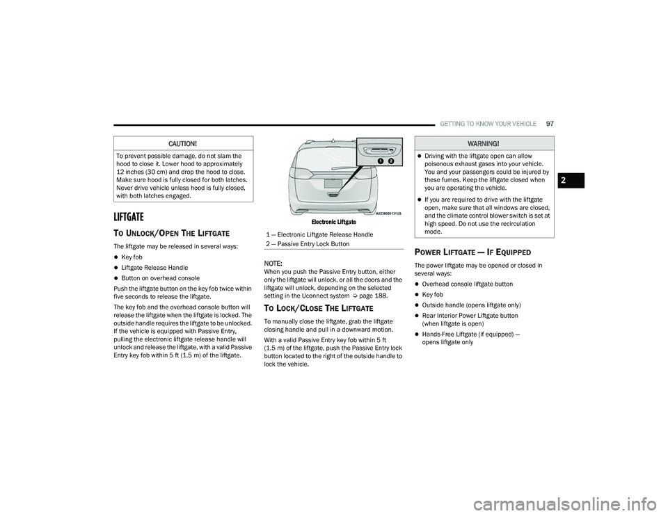
Electronic Liftgate
NOTE:When you push the Passive Entry button, either
only the liftgate will unlock, or all the doors and the
liftgate will unlock, depending on the selected
setting in the Uconnect system Ú
page 188.
TO LOCK/CLOSE THE LIFTGATE
To manually close the liftgate, grab the liftgate
closing handle and pull in a downward motion.
With a valid Passive Entry key fob within 5 ft
(1.5 m) of the liftgate, push the Passive Entry lock
button located to the right of the outside handle to
lock the vehicle.
POWER LIFTGATE — IF EQUIPPED
The power liftgate may be opened or closed in
several ways:
Overhead console liftgate button
Key fob
Outside handle (opens liftgate only)
Rear Interior Power Liftgate button
(when liftgate is open)
Hands-Free Liftgate (if equipped) —
opens liftgate only
CAUTION!
To prevent possible damage, do not slam the
hood to close it. Lower hood to approximately
12 inches (30 cm) and drop the hood to close.
Make sure hood is fully closed for both latches.
Never drive vehicle unless hood is fully closed,
with both latches engaged.
1 — Electronic Liftgate Release Handle
2 — Passive Entry Lock Button
WARNING!
Driving with the liftgate open can allow
poisonous exhaust gases into your vehicle.
You and your passengers could be injured by
these fumes. Keep the liftgate closed when
you are operating the vehicle.
If you are required to drive with the liftgate
open, make sure that all windows are closed,
and the climate control blower switch is set at
high speed. Do not use the recirculation
mode.
2
22_RUP_OM_EN_USC_t.book Page 97
Page 102 of 384

100GETTING TO KNOW YOUR VEHICLE
If the power liftgate encounters multiple
obstructions within the same cycle, the system
will automatically stop. If this occurs, the liftgate
must be operated manually.
The power liftgate will release, but not power
open, in temperatures below −12°F (−24°C).
Be sure to remove any buildup of snow or ice
from the liftgate before opening the liftgate.
If the liftgate is left open for an extended period
of time, the liftgate may need to be closed
manually to reset power liftgate functionality.
The Hands-Free Liftgate only works to open the
liftgate. Gas props support the liftgate in the open position.
However, because the gas pressure drops with
temperature, it may be necessary to assist the
props when opening the liftgate in cold weather.
NOTE:Allow the power system to open the liftgate.
Manually pushing or pulling the liftgate may
activate the liftgate obstacle detection feature and
stop the power operation or reverse its direction.
CARGO AREA FEATURES
Cargo Area Storage
When the third row seats are not in the stowed
position, there is a large area for cargo storage.
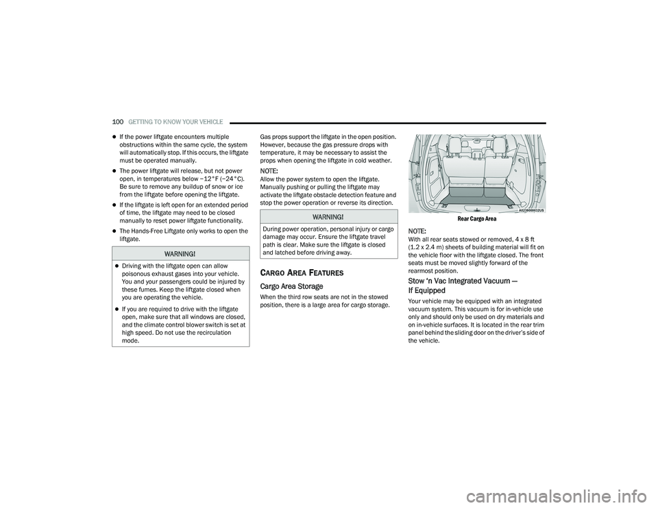
Rear Cargo Area
NOTE:With all rear seats stowed or removed, 4 x 8 ft
(1.2 x 2.4 m) sheets of building material will fit on
the vehicle floor with the liftgate closed. The front
seats must be moved slightly forward of the
rearmost position.
Stow ‘n Vac Integrated Vacuum —
If Equipped
Your vehicle may be equipped with an integrated
vacuum system. This vacuum is for in-vehicle use
only and should only be used on dry materials and
on in-vehicle surfaces. It is located in the rear trim
panel behind the sliding door on the driver’s side of
the vehicle.
WARNING!
Driving with the liftgate open can allow
poisonous exhaust gases into your vehicle.
You and your passengers could be injured by
these fumes. Keep the liftgate closed when
you are operating the vehicle.
If you are required to drive with the liftgate
open, make sure that all windows are closed,
and the climate control blower switch is set at
high speed. Do not use the recirculation
mode.
WARNING!
During power operation, personal injury or cargo
damage may occur. Ensure the liftgate travel
path is clear. Make sure the liftgate is closed
and latched before driving away.
22_RUP_OM_EN_USC_t.book Page 100
Page 105 of 384

GETTING TO KNOW YOUR VEHICLE103
(Continued)
(Continued)
NOTE:To access crevice or upholstery attachments, open
the front Attachment Compartment.
Crevice Tool — Able to reach into tight
spaces including the seat latches located in
the floor.
Upholstery Tool — Use to agitate dirt and
debris from carpets and seats. This tool can
also be used to pick up pet hair.
Hose Extension — Use to add another 12 ft
(3.6 m) of usable length to the vacuum
hose. Hose extension is provided in a bag
attached to a grocery hook behind the third
row seat on the driver’s side.
4. Push the vacuum on/off button located under the vacuum nozzle storage location.
Use vacuum as needed.
NOTE:
When the vacuum is ON, the LED indicator
on the on/off button will illuminate.
When the vacuum is OFF, the LED indicator
will also be off.
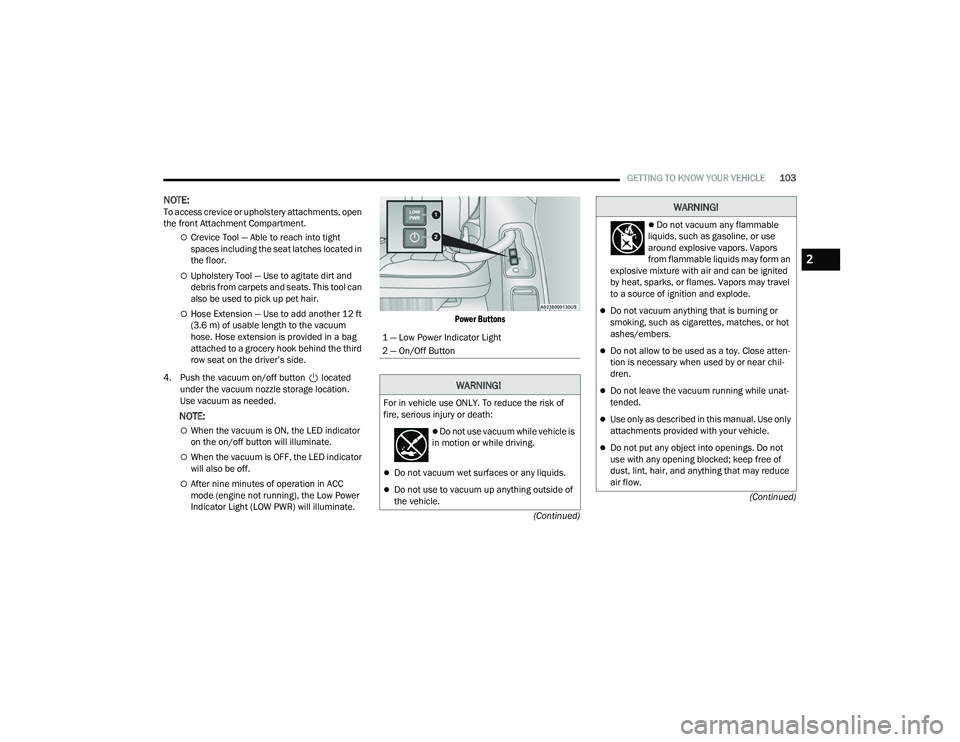
After nine minutes of operation in ACC
mode (engine not running), the Low Power
Indicator Light (LOW PWR) will illuminate.
Power Buttons
1 — Low Power Indicator Light
2 — On/Off Button
WARNING!
For in vehicle use ONLY. To reduce the risk of
fire, serious injury or death:
Do not use vacuum while vehicle is
in motion or while driving.
Do not vacuum wet surfaces or any liquids.
Do not use to vacuum up anything outside of
the vehicle.
Do not vacuum any flammable
liquids, such as gasoline, or use
around explosive vapors. Vapors
from flammable liquids may form an
explosive mixture with air and can be ignited
by heat, sparks, or flames. Vapors may travel
to a source of ignition and explode.
Do not vacuum anything that is burning or
smoking, such as cigarettes, matches, or hot
ashes/embers.
Do not allow to be used as a toy. Close atten -
tion is necessary when used by or near chil -
dren.
Do not leave the vacuum running while unat -
tended.
Use only as described in this manual. Use only
attachments provided with your vehicle.
Do not put any object into openings. Do not
use with any opening blocked; keep free of
dust, lint, hair, and anything that may reduce
air flow.
WARNING!
2
22_RUP_OM_EN_USC_t.book Page 103
Page 121 of 384

GETTING TO KNOW YOUR INSTRUMENT PANEL119
Defaults
Restore
Cancel
Speed Warning — If Equipped
Push and release the up or down arrow
button until Speed Warning is highlighted in the
instrument cluster display. Push and release the
OK button to enter Speed Warning. Use the up
or down arrow button to turn the Speed Warning
ON or OFF, then push and release the OK button to
confirm the selection. If the ON status is selected,
use the up or down arrow button to set the
desired speed, then push the OK button to set the
speed for the Speed Warning. A Speed Warning
light will illuminate in the instrument cluster, with a
number matching the set speed, with a pop-up
message to inform the driver that the Speed
Warning has been set to the desired speed. Each
time the set speed is exceeded, a single chime will
sound and a pop-up warning message will display.
If the set speed is exceeded more than 2 mph
(3 km/h), a continuous chime will sound for up to
10 seconds, or until the speed is no longer
exceeded. The telltale in the instrument cluster will
also change from white to yellow, and a pop-up
warning message will pop-up on the instrument
cluster display.
NOTE:Speed Warning is unavailable while KeySense is
in use.
BATTERY SAVER ON/BATTERY SAVER
M
ODE MESSAGE — ELECTRICAL LOAD
R
EDUCTION ACTIONS — IF EQUIPPED
This vehicle is equipped with an Intelligent Battery
Sensor (IBS) to perform additional monitoring of
the electrical system and status of the vehicle
battery.
In cases when the IBS detects charging system
failure, or the 12 Volt vehicle battery conditions are
deteriorating, electrical load reduction actions will
take place to extend the driving time and distance
of the vehicle. This is done by reducing power to or
turning off non-essential 12 Volt electrical loads.
Load reduction will be functional when the vehicle
propulsion system is active.
The vehicle may not be running depending on the
High Voltage (HV) battery State Of Charge (SOC) or
temperature. It will display a message if there is a
risk of battery depletion to the point where the
vehicle may stall due to lack of electrical supply, or
will not restart after the current drive cycle.
When 12 Volt load reduction is activated, the
message “Battery Saver On” or “Battery Saver
Mode” will appear in the instrument cluster display.
These messages indicate the vehicle battery has a
low state of charge and continues to lose electrical
charge at a rate that the charging system cannot
sustain.
Current
(MPG,
L/100km,
or km/L)
Trip B Distance Trip A Distance
Base Instrument Cluster Display
Screen Setup Options:
Center
None Compass Outside Temp
Time Range Average
(MPG,
L/100km,
or km/L)
Current
(MPG,
L/100km,
or km/L) Trip A Distance Trip B Distance
Audio Menu
Title Menu Title Digital Speed
Base Instrument Cluster Display
Screen Setup Options:
Upper Right
3
22_RUP_OM_EN_USC_t.book Page 119
Page 130 of 384

128GETTING TO KNOW YOUR INSTRUMENT PANEL
KeySense Indicator Light —
If Equipped
The KeySense indicator is illuminated
when a KeySense key is detected upon
startup of the vehicle. The indicator will
remain lit for the entire key cycle as a
reminder that the KeySense key is in use. While
the KeySense key is in use, the vehicle will respond
to settings associated with the KeySense profile
Ú page 14.
LaneSense Indicator Light — If Equipped
The LaneSense indicator light illuminates
solid green when both lane markings
have been detected and the system is
“armed” and ready to provide visual and
torque warnings if an unintentional lane departure
occurs Ú page 166.
Parking/Headlights On Indicator Light
This indicator light will illuminate when
the parking lights or headlights are
turned on.
Stop/Start Active Indicator Light —
If Equipped
This indicator light will illuminate when
the Stop/Start function is in “Autostop”
mode Úpage 143.
Turn Signal Indicator Lights
When the left or right turn signal is
activated, the turn signal indicator will
flash independently and the
corresponding exterior turn signal lamps
will flash. Turn signals can be activated when the
multifunction lever is moved down (left) or
up (right).
NOTE:
A continuous chime will sound if the vehicle is
driven more than 1 mile (1.6 km) with either
turn signal on.
Check for an inoperative outside light bulb if
either indicator flashes at a rapid rate.
WHITE INDICATOR LIGHTS
Adaptive Cruise Control (ACC) Ready
Light — If Equipped
This indicator light will illuminate when
the vehicle equipped with ACC has been
turned on but not set Ú page 147.
Cruise Control Ready Indicator Light
This indicator light will illuminate when
the cruise control is ready, but not set
Úpage 146.
LaneSense Indicator Light — If Equipped
When the LaneSense system is ON, but
not armed, the LaneSense indicator light
illuminates solid white. This occurs when
only left, right, or neither lane line has
been detected. If a single lane line is detected, the
system is ready to provide only visual warnings if
an unintentional lane departure occurs on the
detected lane line Ú page 166.
Speed Warning Indicator Light
The white indicator will illuminate along
with a pop-up message (Speed Warning
Set to XX followed by unit), once the
feature is enabled. When the set speed is
exceeded, a continuous chime (up to 10 seconds
or until the speed is no longer exceeded) will sound
along with a Speed Warning Exceeded pop-up
message and the indicator light will turn yellow and
flash.
NOTE:The number “31” is only an example of a speed
that can be selected.
Set Speed Display
The Set Speed Display indicator light
indicates the set speed for the Cruise
Control and Adaptive Cruise Control
(ACC) settings.
22_RUP_OM_EN_USC_t.book Page 128
Page 135 of 384

STARTING AND OPERATING133
(Continued)
(Continued)
AutoPark In Stop/Start Autostop Mode
AutoPark will engage when all of these condi
-
tions are met:
Vehicle is equipped with a gear selector
Vehicle is not in PARK
Vehicle speed is 1.2 mph (1.9 km/h) or less
Driver’s door is ajar
Driver’s seat belt is unbuckled or brake pedal is
not pressed
The message “ AutoPark Engaged ” will display in
the instrument cluster.
WARNING!
Never use the PARK position as a substitute
for the parking brake. Always apply the
parking brake fully when exiting the vehicle to
guard against vehicle movement and possible
injury or damage.
Your vehicle could move and injure you and
others if it is not in PARK. Check by trying to
move the transmission gear selector out of
PARK with the brake pedal released. Make
sure the transmission is in PARK before
exiting the vehicle.
The transmission may not engage PARK if the
vehicle is moving. Always bring the vehicle to a
complete stop before shifting to PARK, and
verify that the transmission gear position indi -
cator solidly indicates PARK (P) without
blinking. Ensure that the vehicle is completely
stopped, and the PARK position is properly
indicated, before exiting the vehicle.
It is dangerous to shift out of PARK or
NEUTRAL if the engine speed is higher than
idle speed. If your foot is not firmly pressing
the brake pedal, the vehicle could accelerate
quickly forward or in reverse. You could lose
control of the vehicle and hit someone or
something. Only shift into gear when the
engine is idling normally and your foot is firmly
pressing the brake pedal.
WARNING!
Unintended movement of a vehicle could
injure those in or near the vehicle. As with all
vehicles, you should never exit a vehicle while
the engine is running. Before exiting a vehicle,
always come to a complete stop, then apply
the parking brake, shift the transmission into
PARK, and turn the ignition OFF. When the
ignition is in the OFF position, the transmis -
sion is locked in PARK, securing the vehicle
against unwanted movement.
When exiting the vehicle, always make sure
the ignition is in the OFF position, remove the
key fob from the vehicle, and lock the vehicle.
Never leave children alone in a vehicle, or
with access to an unlocked vehicle. Allowing
children to be in a vehicle unattended is
dangerous for a number of reasons. A child or
others could be seriously or fatally injured.
Children should be warned not to touch the
parking brake, brake pedal or the transmis -
sion gear selector.
Do not leave the key fob in or near the vehicle
(or in a location accessible to children), and do
not leave the ignition in the ACC or ON/RUN
position. A child could operate power
windows, other controls, or move the vehicle.
WARNING!
4
22_RUP_OM_EN_USC_t.book Page 133