2022 CHRYSLER PACIFICA Seat
[x] Cancel search: SeatPage 307 of 384

IN CASE OF EMERGENCY305
To Reset The Manual Park Release:
1. Apply firm pressure to the brake pedal while seated in the driver’s seat.
2. Pull the tether strap out again, then release it.
3. Allow the tether to retract with the lever back to its original position.
4. Verify that the transmission is in PARK (P).
5. Confirm that the tether has retracted fully and reinstall the access cover. If the access
cover cannot be reinstalled, repeat
steps 1 through 4.
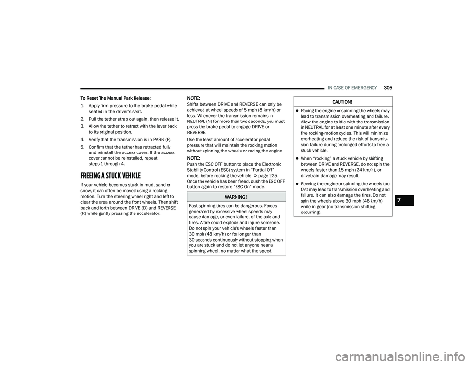
FREEING A STUCK VEHICLE
If your vehicle becomes stuck in mud, sand or
snow, it can often be moved using a rocking
motion. Turn the steering wheel right and left to
clear the area around the front wheels. Then shift
back and forth between DRIVE (D) and REVERSE
(R) while gently pressing the accelerator.
NOTE:Shifts between DRIVE and REVERSE can only be
achieved at wheel speeds of 5 mph (8 km/h) or
less. Whenever the transmission remains in
NEUTRAL (N) for more than two seconds, you must
press the brake pedal to engage DRIVE or
REVERSE.
Use the least amount of accelerator pedal
pressure that will maintain the rocking motion
without spinning the wheels or racing the engine.
NOTE:Push the ESC OFF button to place the Electronic
Stability Control (ESC) system in “Partial Off”
mode, before rocking the vehicle Ú page 225.
Once the vehicle has been freed, push the ESC OFF
button again to restore “ESC On” mode.
WARNING!
Fast spinning tires can be dangerous. Forces
generated by excessive wheel speeds may
cause damage, or even failure, of the axle and
tires. A tire could explode and injure someone.
Do not spin your vehicle's wheels faster than
30 mph (48 km/h) or for longer than
30 seconds continuously without stopping when
you are stuck and do not let anyone near a
spinning wheel, no matter what the speed.
CAUTION!
Racing the engine or spinning the wheels may
lead to transmission overheating and failure.
Allow the engine to idle with the transmission
in NEUTRAL for at least one minute after every
five rocking-motion cycles. This will minimize
overheating and reduce the risk of transmis -
sion failure during prolonged efforts to free a
stuck vehicle.
When “rocking” a stuck vehicle by shifting
between DRIVE and REVERSE, do not spin the
wheels faster than 15 mph (24 km/h), or
drivetrain damage may result.
Revving the engine or spinning the wheels too
fast may lead to transmission overheating and
failure. It can also damage the tires. Do not
spin the wheels above 30 mph (48 km/h)
while in gear (no transmission shifting
occurring).
7
22_RUP_OM_EN_USC_t.book Page 305
Page 309 of 384

IN CASE OF EMERGENCY307
Vehicle Recovery Tow Points
Your vehicle is equipped with Vehicle Recovery
Points that can be used to recover a disabled
vehicle, located on the underbody of the vehicle.
NOTE:
Ensure that the towing service tow hooks are
properly seated and secured in the attachment
points.
This recovery tow feature should be used by a
trained professional only.
Use approved receptacle location to free the
disabled vehicle from its environment.
Front Recovery Points
If you must use the accessories (wipers,
defrosters, etc.) while being towed, the ignition
must be in the ON/RUN mode, not the ACC mode.
NOTE:The Safehold feature will engage the Electric Park
Brake whenever the driver's door is opened (if the
ignition is ON, transmission is not in PARK, and
brake pedal is released). If you are towing this
vehicle with the ignition in the ON/RUN mode, you
must manually disable the Electric Park Brake
each time the driver's door is opened, by pressing
the brake pedal and then releasing the EPB.
If the key fob is unavailable or the vehicle's battery
is discharged, detailed instructions on shifting the
transmission out of PARK in order to move the
vehicle Ú
page 304.
CAUTION!
Recovery feature:
Is to be used by a professional ONLY.
Is used only to provide recovery of the vehicle.
Is NOT to be used to recover secondary
vehicle.
Is NOT to be used for transporting the vehicle
over the road, i.e. “Flat Towing”.
Is to be used by a professional ONLY.
Is used only to provide recovery of the vehicle.
Is NOT to be used to recover secondary
vehicle.
Is NOT to be used for transporting the vehicle
over the road, i.e. “Flat Towing”.
Recovery load should:
Be applied at constant speed.
Be applied parallel to the center line of the
length of the vehicle.
Not be an abrupt acceleration.
Be applied at constant speed.
Be applied parallel to the center line of the
length of the vehicle.
Not be an abrupt acceleration.
CAUTION!
Do not use sling-type equipment when towing.
Vehicle damage may occur.
When securing the vehicle to a flatbed truck,
do not attach to front or rear suspension
components. Damage to your vehicle may
result from improper towing.
Ensure that the Electric Park Brake is
released, and remains released, while being
towed.
7
22_RUP_OM_EN_USC_t.book Page 307
Page 322 of 384

320SERVICING AND MAINTENANCE
BODY LUBRICATION
Locks and all body pivot points, including such
items as seat tracks, door hinge pivot points and
rollers, liftgate, tailgate, decklid, sliding doors and
hood hinges, should be lubricated periodically. Use
a lithium-based grease, such as Mopar® Spray
White Lube to ensure quiet, easy operation and to
protect against rust and wear. Prior to the
application of any lubricant, the parts concerned
should be wiped clean to remove dust and grit;
after lubricating, excess oil and grease should be
removed. Particular attention should also be given
to hood latching components to ensure proper
function. When performing other underhood
services, the hood latch release mechanism, and
safety catch should be cleaned and lubricated.
The external lock cylinders should be lubricated
twice a year, preferably in the Autumn and Spring.
Apply a small amount of a high quality lubricant,
such as Mopar® Lock Cylinder Lubricant directly
into the lock cylinder.
WINDSHIELD WIPER BLADES
Clean the rubber edges of the wiper blades and the
windshield periodically with a sponge or soft cloth
and a mild nonabrasive cleaner. This will remove
accumulations of salt or road film. Operation of the wipers on dry glass for long
periods may cause deterioration of the wiper
blades. Always use washer fluid when using the
wipers to remove salt or dirt from a dry windshield.
Avoid using the wiper blades to remove frost or ice
from the windshield. Keep the blade rubber out of
contact with petroleum products such as engine
oil, gasoline, etc.
NOTE:Life expectancy of wiper blades varies depending
on geographical area and frequency of use. If chat
-
tering, marks, water lines or wet spots are present,
clean the wiper blades or replace as necessary.
The wiper blades and wiper arms should be
inspected periodically, not just when wiper
performance problems are experienced. This
inspection should include the following points:
Wear or uneven edges
Foreign material
Hardening or cracking
Deformation or fatigue
If a wiper blade or wiper arm is damaged, replace
the affected wiper arm or blade with a new unit. Do
not attempt to repair a wiper arm or blade that is
damaged.
Front Wiper Blade Removal/Installation
1. Lift the wiper arm to raise the wiper blade off of the glass, until the wiper arm is in the full
up position.
Wiper Blade With Release Tab In Locked Position
CAUTION!
Do not allow the wiper arm to spring back
against the glass without the wiper blade in
place or the glass may be damaged.
1 — Wiper Blade
2 — Release Tab
3 — Wiper Arm
22_RUP_OM_EN_USC_t.book Page 320
Page 333 of 384

SERVICING AND MAINTENANCE331
F15 40 Amp Green –CBC / Power Locks
F16 –20 Amp Yellow ECM
F17 30 Amp Pink –Starter
F18 40 Amp Green –CBC / EXT LIGHTS
F19 25 Amp Clear –2nd Row Folding Seats Solenoid LT *
F20 –10 Amp Red A/C Compressor Clutch
F21 25 Amp Clear –2nd Row Folding Seat Solenoid RT *
F22 ––Not Populated
F23 ––Not Populated
F24 –20 Amp Yellow RR Wiper
F25 –10 Amp RedHands Free Dr Mod / Active Grille
Shutter / Pwr Mirror / VRM
F26 40 Amp Green –Front HVAC Blower Motor
F27 25 Amp Clear –RR Slide Door Module-RT *
F28 –10 Amp RedDiagnostic Port / USB+(IP) / Video
USB Port / Overhead DVD Player(Aftermarket)
F29 ––Not Populated
F30 –15 Amp BlueMedia HUB / Power Lumbar *
F31 ––Not Populated
F32 20 Amp Blue –ECM
CavityCartridge Fuse Blade FuseDescription
*If Equipped
8
22_RUP_OM_EN_USC_t.book Page 331
Page 334 of 384

332SERVICING AND MAINTENANCE
F33 30 Amp Pink –Power Liftgate Module *
F34 25 Amp Clear –RR Door Module-LT *
F35 25 Amp Clear –Sunroof *
F36 ––Not Populated
F37 40 Amp Green –CBC / Exterior Lights
F38 60 Amp Yellow –Vacuum Cleaner *
F39 25 Amp Clear –Rear HVAC Blower Motor
F40 ––Not Populated
F41 ––Not Populated
F42 40 Amp Green –Folding Seat Module *
F43 –20 Amp Yellow Fuel Pump Motor
F44 30 Amp Pink –CBC / Interior Lights
F45 30 Amp Pink –Power Inverter *
F46 30 Amp Pink –Driver Door Module
F47 30 Amp Pink –Passenger Door Module
F48 ––Not Populated
F49 25 Amp Clear –RR Sliding Door Module-LT *
F50 25 Amp Clear –RR Door Module-RT *
F51 30 Amp Pink –Front Wiper
F52 30 Amp Pink –Brake Vacuum Pump
Cavity Cartridge Fuse Blade FuseDescription
*If Equipped
22_RUP_OM_EN_USC_t.book Page 332
Page 337 of 384

SERVICING AND MAINTENANCE335
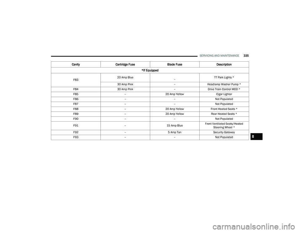
F83 20 Amp Blue
– TT Park Lights *
30 Amp Pink –Headlamp Washer Pump *
F84 30 Amp Pink –Drive Train Control MOD *
F85 –20 Amp Yellow Cigar Lighter
F86 ––Not Populated
F87 ––Not Populated
F88 –20 Amp Yellow Front Heated Seats *
F89 –20 Amp Yellow Rear Heated Seats *
F90 ––Not Populated
F91 –15 Amp BlueFront Ventilated Seats/Heated
Steering Wheel *
F92 –5 Amp Tan Security Gateway
F93 ––Not Populated
CavityCartridge Fuse Blade FuseDescription
*If Equipped
8
22_RUP_OM_EN_USC_t.book Page 335
Page 338 of 384

336SERVICING AND MAINTENANCE
30 Amp mini fuse is substituted for 25 Amp Circuit Breaker. F94
40 Amp Green –ESC Motor Pump
F95A –10 Amp RedUSB Charge Port — ACC/RUN
F95B –10 Amp RedSelectable Fuse Location – USB IP
(Direct) B+
F96 –10 Amp Red Airbag
F97 –10 Amp Red Airbag
F98 –15 Amp Blue Left HID Headlamp *
F99 30 Amp Pink –Trailer Tow Elect Brake Module *
F100 –10 Amp RedHeadlamp Level / RR Camera /
Blindspot / Humidity SNSR / In Car Temp SNSR / Headlamp SW *
Circuit Breakers
CB1 25 AmpPower Seats (Driver)
CB2 25 Amp *Power Seats (Pass)
CB3 25 AmpFRT PWR Window W/O Door Nodes +
RR PWR Window Lockout
Cavity Cartridge Fuse Blade FuseDescription
*If Equipped
22_RUP_OM_EN_USC_t.book Page 336
Page 346 of 384

344SERVICING AND MAINTENANCE
To determine the maximum loading conditions of
your vehicle, locate the statement “The combined
weight of occupants and cargo should never
exceed XXX kg or XXX lbs” on the Tire and Loading
Information placard. The combined weight of
occupants, cargo/luggage and trailer tongue
weight (if applicable) should never exceed the
weight referenced here.
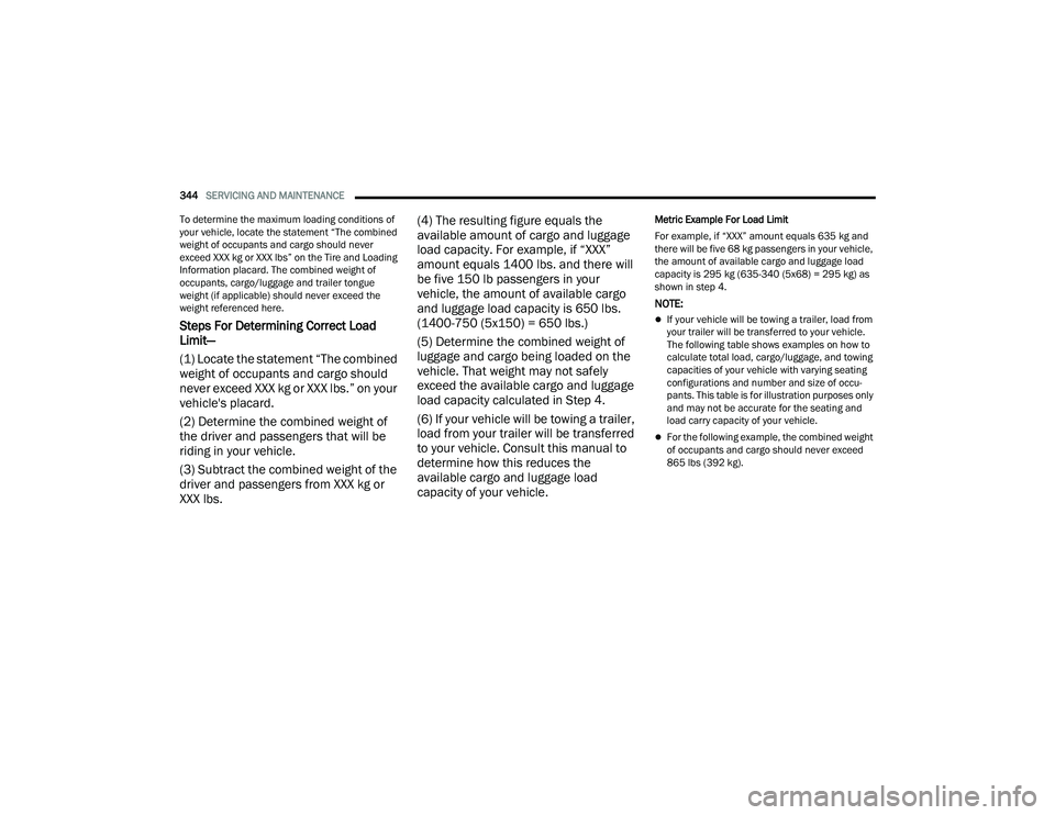
Steps For Determining Correct Load
Limit—
(1) Locate the statement “The combined
weight of occupants and cargo should
never exceed XXX kg or XXX lbs.” on your
vehicle's placard.
(2) Determine the combined weight of
the driver and passengers that will be
riding in your vehicle.
(3) Subtract the combined weight of the
driver and passengers from XXX kg or
XXX lbs. (4) The resulting figure equals the
available amount of cargo and luggage
load capacity. For example, if “XXX”
amount equals 1400 lbs. and there will
be five 150 lb passengers in your
vehicle, the amount of available cargo
and luggage load capacity is 650 lbs.
(1400-750 (5x150) = 650 lbs.)
(5) Determine the combined weight of
luggage and cargo being loaded on the
vehicle. That weight may not safely
exceed the available cargo and luggage
load capacity calculated in Step 4.
(6) If your vehicle will be towing a trailer,
load from your trailer will be transferred
to your vehicle. Consult this manual to
determine how this reduces the
available cargo and luggage load
capacity of your vehicle.
Metric Example For Load Limit
For example, if “XXX” amount equals 635 kg and
there will be five 68 kg passengers in your vehicle,
the amount of available cargo and luggage load
capacity is 295 kg (635-340 (5x68) = 295 kg) as
shown in step 4.
NOTE:
If your vehicle will be towing a trailer, load from
your trailer will be transferred to your vehicle.
The following table shows examples on how to
calculate total load, cargo/luggage, and towing
capacities of your vehicle with varying seating
configurations and number and size of occu
-
pants. This table is for illustration purposes only
and may not be accurate for the seating and
load carry capacity of your vehicle.
For the following example, the combined weight
of occupants and cargo should never exceed
865 lbs (392 kg).
22_RUP_OM_EN_USC_t.book Page 344