2022 CHRYSLER PACIFICA HYBRID tire size
[x] Cancel search: tire sizePage 239 of 384

SAFETY237
NOTE:
The TPMS is not intended to replace normal tire
care and maintenance, or to provide warning of
a tire failure or condition.
The TPMS should not be used as a tire pressure
gauge while adjusting your tire pressure.
Driving on a significantly underinflated tire
causes the tire to overheat and can lead to tire
failure. Underinflation also reduces fuel effi -
ciency and tire tread life, and may affect the
vehicle’s handling and stopping ability.
The TPMS is not a substitute for proper tire
maintenance, and it is the driver’s responsibility
to maintain correct tire pressure using an accu -
rate tire pressure gauge, even if underinflation
has not reached the level to trigger illumination
of the TPMS Warning Light.
Seasonal temperature changes will affect tire
pressure, and the TPMS will monitor the actual
tire pressure in the tire.
Premium System
The Tire Pressure Monitoring System (TPMS) uses
wireless technology with wheel rim mounted
electronic sensors to monitor tire pressure levels.
Sensors, mounted to each wheel as part of the
valve stem, transmit tire pressure readings to the
receiver module.
NOTE:It is particularly important for you to check the tire
pressure in all of the tires on your vehicle monthly
and to maintain the proper pressure.
The TPMS consists of the following components:
Receiver module
Four Tire Pressure Monitoring System sensors
Various Tire Pressure Monitoring System
messages, which display in the instrument
cluster
Tire Pressure Monitoring System Warning Light
SERVICE TPMS WARNING
When a system fault is detected, the Tire Pressure
Monitoring System (TPMS) Warning Light will flash
on and off for 75 seconds and then remain on
solid. The system fault will also sound a chime. In
addition, the instrument cluster will display a
"SERVICE TPM SYSTEM" message for a minimum
of five seconds and then display dashes (--) in
place of the pressure value to indicate which
sensor is not being received.
CAUTION!
The TPMS has been optimized for the original
equipment tires and wheels. TPMS pressures
and warning have been established for the tire
size equipped on your vehicle. Undesirable
system operation or sensor damage may
result when using replacement equipment
that is not of the same size, type, and/or style.
The TPMS sensor is not designed for use on
aftermarket wheels and may contribute to a
poor overall system performance or sensor
damage. Customers are encouraged to use
OEM wheels to ensure proper TPMS feature
operation.
Using aftermarket tire sealants may cause the
Tire Pressure Monitoring System (TPMS)
sensor to become inoperable. After using an
aftermarket tire sealant it is recommended
that you take your vehicle to an authorized
dealer to have your sensor function checked.
After inspecting or adjusting the tire pressure
always reinstall the valve stem cap. This will
prevent moisture and dirt from entering the
valve stem, which could damage the TPMS
sensor.
6
22_RUP_OM_EN_USC_t.book Page 237
Page 293 of 384

IN CASE OF EMERGENCY291
6. Install the inflatable spare on the vehicle, located in the rear cargo area of the vehicle.
Mounting Inflatable Spare Tire
NOTE:Do not install the wheel cover on the inflatable
spare tire.
7. Leave the vehicle on the jack and start inflating the inflatable spare after the tire has
been mounted to the vehicle. Secure the
wheel to the hub by tightening the nuts with
the wrench. After inflation, once the vehicle is
lowered you will have a second opportunity to
torque the lug nuts Ú page 360.
8. Inflate the tire to the prescribed pressure 60 psi (4.2 Bar) using the Portable Air
Compressor Ú page 293 or Tire Service Kit if
equipped Ú page 294.
9. Lower the vehicle once the inflatable Spare has reached its pressure and the
compressor-hose has been removed from the
tire valve. 10. Finish tightening the lug nuts. Push down on
the wrench while at the end of the handle for
increased leverage. Tighten the lug nuts in a
star pattern until each nut has been tightened
twice Ú page 360. If in doubt about the
correct tightness, have them checked with a
torque wrench by an authorized dealer or at a
service station.
11. Lower the jack to its fully-closed position.
12. Place the deflated (flat) tire and foam tray cover assembly in the rear cargo area. Do not
stow the deflated tire in the inflatable spare
tire location. Have the full-sized tire repaired or
replaced, as soon as possible.
WARNING!
To avoid the risk of forcing the vehicle off the
jack, do not tighten the wheel nuts fully until the
vehicle has been lowered. Failure to follow this
warning may result in serious injury.
CAUTION!
Be sure to mount the inflatable spare tire with
the valve stem facing outward. The vehicle could
be damaged if the inflatable spare tire is
mounted incorrectly.
WARNING!
A loose tire or jack thrown forward in a collision
or hard stop could endanger the occupants of
the vehicle. Always stow the jack parts and the
spare tire in the places provided. Have the
deflated (flat) tire repaired or replaced
immediately.
7
22_RUP_OM_EN_USC_t.book Page 291
Page 341 of 384
SERVICING AND MAINTENANCE339
TIRES
TIRE SAFETY INFORMATION
Tire safety information will cover aspects of the
following information: Tire Markings, Tire
Identification Numbers, Tire Terminology and
Definitions, Tire Pressures, and Tire Loading.
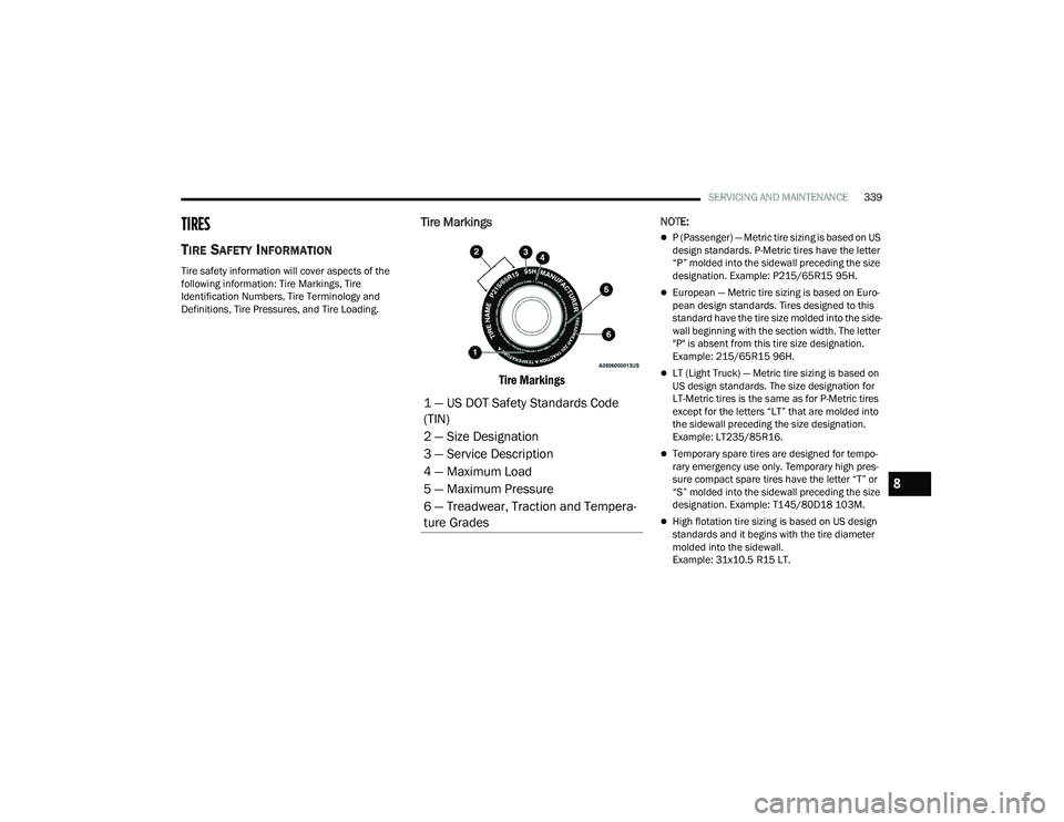
Tire Markings
Tire Markings
NOTE:
P (Passenger) — Metric tire sizing is based on US
design standards. P-Metric tires have the letter
“P” molded into the sidewall preceding the size
designation. Example: P215/65R15 95H.
European — Metric tire sizing is based on Euro -
pean design standards. Tires designed to this
standard have the tire size molded into the side -
wall beginning with the section width. The letter
"P" is absent from this tire size designation.
Example: 215/65R15 96H.
LT (Light Truck) — Metric tire sizing is based on
US design standards. The size designation for
LT-Metric tires is the same as for P-Metric tires
except for the letters “LT” that are molded into
the sidewall preceding the size designation.
Example: LT235/85R16.
Temporary spare tires are designed for tempo -
rary emergency use only. Temporary high pres -
sure compact spare tires have the letter “T” or
“S” molded into the sidewall preceding the size
designation. Example: T145/80D18 103M.
High flotation tire sizing is based on US design
standards and it begins with the tire diameter
molded into the sidewall.
Example: 31x10.5 R15 LT.
1 — US DOT Safety Standards Code
(TIN)
2 — Size Designation
3 — Service Description
4 — Maximum Load
5 — Maximum Pressure
6 — Treadwear, Traction and Tempera -
ture Grades
8
22_RUP_OM_EN_USC_t.book Page 339
Page 342 of 384
340SERVICING AND MAINTENANCE
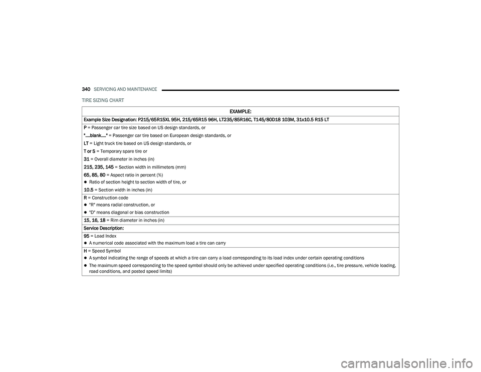
TIRE SIZING CHART
EXAMPLE:
Example Size Designation: P215/65R15XL 95H, 215/65R15 96H, LT235/85R16C, T145/80D18 103M, 31x10.5 R15 LT
P = Passenger car tire size based on US design standards, or
"....blank...." = Passenger car tire based on European design standards, or
LT = Light truck tire based on US design standards, or
T or S = Temporary spare tire or
31 = Overall diameter in inches (in)
215, 235, 145 = Section width in millimeters (mm)
65, 85, 80 = Aspect ratio in percent (%)
Ratio of section height to section width of tire, or
10.5 = Section width in inches (in)
R = Construction code
"R" means radial construction, or
"D" means diagonal or bias construction
15, 16, 18 = Rim diameter in inches (in)
Service Description:
95 = Load Index
A numerical code associated with the maximum load a tire can carry
H = Speed Symbol
A symbol indicating the range of speeds at which a tire can carry a load corresponding to its load index under certain operating conditions
The maximum speed corresponding to the speed symbol should only be achieved under specified operating conditions (i.e., tire pressure, vehicle loading,
road conditions, and posted speed limits)
22_RUP_OM_EN_USC_t.book Page 340
Page 343 of 384
SERVICING AND MAINTENANCE341
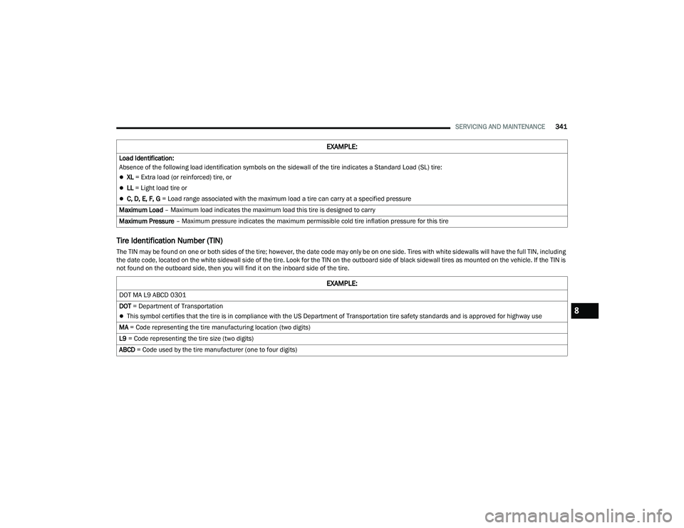
Tire Identification Number (TIN)
The TIN may be found on one or both sides of the tire; however, the date code may only be on one side. Tires with white sidewalls will have the full TIN, including
the date code, located on the white sidewall side of the tire. Look for the TIN on the outboard side of black sidewall tires as mounted on the vehicle. If the TIN is
not found on the outboard side, then you will find it on the inboard side of the tire.Load Identification:
Absence of the following load identification symbols on the sidewall of the tire indicates a Standard Load (SL) tire:
XL = Extra load (or reinforced) tire, or
LL
= Light load tire or
C, D, E, F, G = Load range associated with the maximum load a tire can carry at a specified pressure
Maximum Load – Maximum load indicates the maximum load this tire is designed to carry
Maximum Pressure – Maximum pressure indicates the maximum permissible cold tire inflation pressure for this tire
EXAMPLE:
EXAMPLE:
DOT MA L9 ABCD 0301
DOT = Department of Transportation
This symbol certifies that the tire is in compliance with the US Department of Transportation tire safety standards and is approved for highway use
MA = Code representing the tire manufacturing location (two digits)
L9 = Code representing the tire size (two digits)
ABCD = Code used by the tire manufacturer (one to four digits)8
22_RUP_OM_EN_USC_t.book Page 341
Page 344 of 384
342SERVICING AND MAINTENANCE
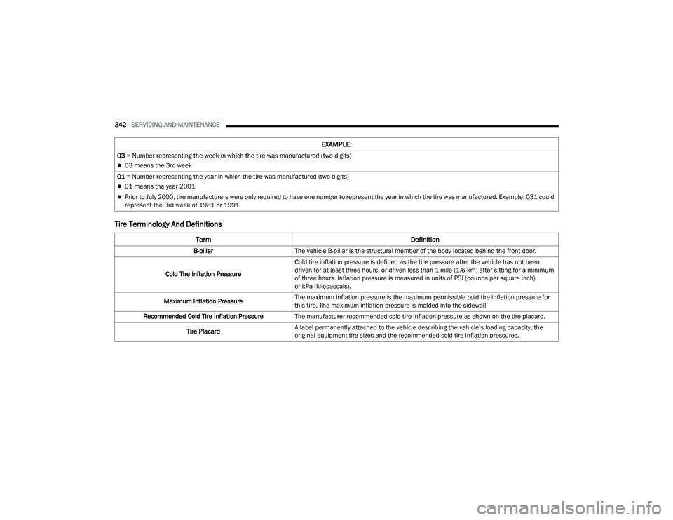
Tire Terminology And Definitions
03 = Number representing the week in which the tire was manufactured (two digits)
03 means the 3rd week
01 = Number representing the year in which the tire was manufactured (two digits)
01 means the year 2001
Prior to July 2000, tire manufacturers were only required to have one number to represent the year in which the tire was manufactured. Example: 031 could
represent the 3rd week of 1981 or 1991
Term Definition
B-pillarThe vehicle B-pillar is the structural member of the body located behind the front door.
Cold Tire Inflation Pressure Cold tire inflation pressure is defined as the tire pressure after the vehicle has not been
driven for at least three hours, or driven less than 1 mile (1.6 km) after sitting for a minimum
of three hours. Inflation pressure is measured in units of PSI (pounds per square inch)
or kPa (kilopascals).
Maximum Inflation Pressure The maximum inflation pressure is the maximum permissible cold tire inflation pressure for
this tire. The maximum inflation pressure is molded into the sidewall.
Recommended Cold Tire Inflation Pressure The manufacturer recommended cold tire inflation pressure as shown on the tire placard.
Tire Placard A label permanently attached to the vehicle describing the vehicle’s loading capacity, the
original equipment tire sizes and the recommended cold tire inflation pressures.
EXAMPLE:
22_RUP_OM_EN_USC_t.book Page 342
Page 345 of 384
SERVICING AND MAINTENANCE343
Tire Loading And Tire Pressure
NOTE:The proper cold tire inflation pressure is listed on
the driver’s side B-pillar or the rear edge of the
driver's side door.
Check the inflation pressure of each tire, including
the spare tire (if equipped), at least monthly and
inflate to the recommended pressure for your
vehicle.
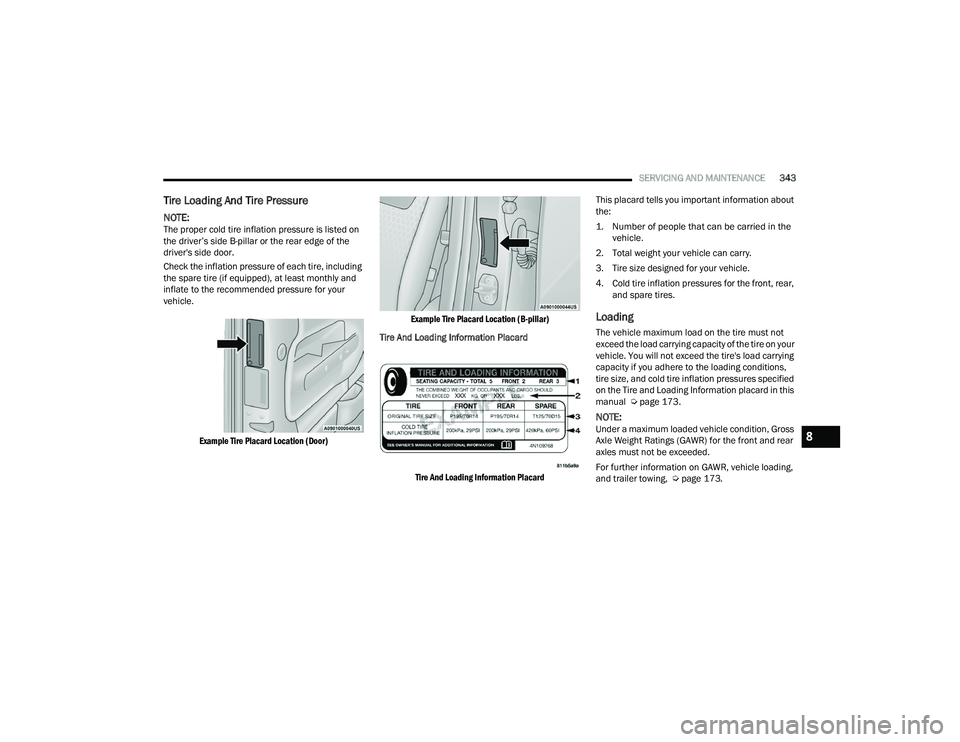
Example Tire Placard Location (Door) Example Tire Placard Location (B-pillar)
Tire And Loading Information Placard
Tire And Loading Information Placard
This placard tells you important information about
the:
1. Number of people that can be carried in the
vehicle.
2. Total weight your vehicle can carry.
3. Tire size designed for your vehicle.
4. Cold tire inflation pressures for the front, rear, and spare tires.
Loading
The vehicle maximum load on the tire must not
exceed the load carrying capacity of the tire on your
vehicle. You will not exceed the tire's load carrying
capacity if you adhere to the loading conditions,
tire size, and cold tire inflation pressures specified
on the Tire and Loading Information placard in this
manual Ú page 173.
NOTE:Under a maximum loaded vehicle condition, Gross
Axle Weight Ratings (GAWR) for the front and rear
axles must not be exceeded.
For further information on GAWR, vehicle loading,
and trailer towing, Ú page 173.8
22_RUP_OM_EN_USC_t.book Page 343
Page 346 of 384
344SERVICING AND MAINTENANCE
To determine the maximum loading conditions of
your vehicle, locate the statement “The combined
weight of occupants and cargo should never
exceed XXX kg or XXX lbs” on the Tire and Loading
Information placard. The combined weight of
occupants, cargo/luggage and trailer tongue
weight (if applicable) should never exceed the
weight referenced here.
Steps For Determining Correct Load
Limit—
(1) Locate the statement “The combined
weight of occupants and cargo should
never exceed XXX kg or XXX lbs.” on your
vehicle's placard.
(2) Determine the combined weight of
the driver and passengers that will be
riding in your vehicle.
(3) Subtract the combined weight of the
driver and passengers from XXX kg or
XXX lbs. (4) The resulting figure equals the
available amount of cargo and luggage
load capacity. For example, if “XXX”
amount equals 1400 lbs. and there will
be five 150 lb passengers in your
vehicle, the amount of available cargo
and luggage load capacity is 650 lbs.
(1400-750 (5x150) = 650 lbs.)
(5) Determine the combined weight of
luggage and cargo being loaded on the
vehicle. That weight may not safely
exceed the available cargo and luggage
load capacity calculated in Step 4.
(6) If your vehicle will be towing a trailer,
load from your trailer will be transferred
to your vehicle. Consult this manual to
determine how this reduces the
available cargo and luggage load
capacity of your vehicle.
Metric Example For Load Limit
For example, if “XXX” amount equals 635 kg and
there will be five 68 kg passengers in your vehicle,
the amount of available cargo and luggage load
capacity is 295 kg (635-340 (5x68) = 295 kg) as
shown in step 4.
NOTE:
If your vehicle will be towing a trailer, load from
your trailer will be transferred to your vehicle.
The following table shows examples on how to
calculate total load, cargo/luggage, and towing
capacities of your vehicle with varying seating
configurations and number and size of occu
-
pants. This table is for illustration purposes only
and may not be accurate for the seating and
load carry capacity of your vehicle.
For the following example, the combined weight
of occupants and cargo should never exceed
865 lbs (392 kg).
22_RUP_OM_EN_USC_t.book Page 344