2022 ALFA ROMEO GIULIA tow
[x] Cancel search: towPage 149 of 248

147
(Continued)
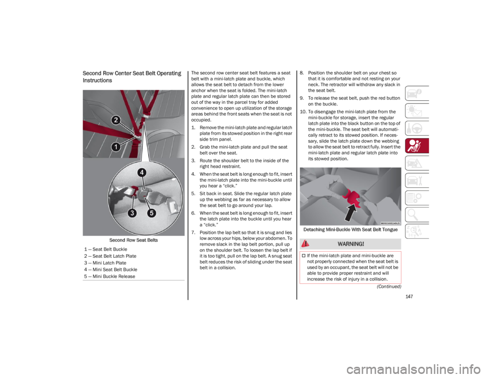
Second Row Center Seat Belt Operating
Instructions
Second Row Seat BeltsThe second row center seat belt features a seat
belt with a mini-latch plate and buckle, which
allows the seat belt to detach from the lower
anchor when the seat is folded. The mini-latch
plate and regular latch plate can then be stored
out of the way in the parcel tray for added
convenience to open up utilization of the storage
areas behind the front seats when the seat is not
occupied.
1. Remove the mini-latch plate and regular latch
plate from its stowed position in the right rear
side trim panel.
2. Grab the mini-latch plate and pull the seat belt over the seat.
3. Route the shoulder belt to the inside of the right head restraint.
4. When the seat belt is long enough to fit, insert the mini-latch plate into the mini-buckle until
you hear a “click.”
5. Sit back in seat. Slide the regular latch plate up the webbing as far as necessary to allow
the seat belt to go around your lap.
6. When the seat belt is long enough to fit, insert the latch plate into the buckle until you hear
a “click.”
7. Position the lap belt so that it is snug and lies low across your hips, below your abdomen. To
remove slack in the lap belt portion, pull up
on the shoulder belt. To loosen the lap belt if
it is too tight, pull on the lap belt. A snug seat
belt reduces the risk of sliding under the seat
belt in a collision. 8. Position the shoulder belt on your chest so
that it is comfortable and not resting on your
neck. The retractor will withdraw any slack in
the seat belt.
9. To release the seat belt, push the red button on the buckle.
10. To disengage the mini-latch plate from the mini-buckle for storage, insert the regular
latch plate into the black button on the top of
the mini-buckle. The seat belt will automati -
cally retract to its stowed position. If neces -
sary, slide the latch plate down the webbing
to allow the seat belt to retract fully. Insert the
mini-latch plate and regular latch plate into
its stowed position.
Detaching Mini-Buckle With Seat Belt Tongue
1 — Seat Belt Buckle
2 — Seat Belt Latch Plate
3 — Mini Latch Plate
4 — Mini Seat Belt Buckle
5 — Mini Buckle Release WARNING!
If the mini-latch plate and mini-buckle are
not properly connected when the seat belt is
used by an occupant, the seat belt will not be
able to provide proper restraint and will
increase the risk of injury in a collision.
22_GA_OM_EN_USC_t.book Page 147
Page 164 of 248

SAFETY
162
(Continued)
Locating The LATCH Anchorages
The lower anchorages are round bars
that are found at the rear of the seat
cushion where it meets the seatback.
Each anchorage is under a cover with
the anchorage symbol on it. Lift the cover to
access the lower anchorage.
LATCH Anchorage Locations
Locating The Upper Tether Anchorages
There are tether strap anchorages
behind each rear seating position
located in the panel between the rear
seatback and the rear window. They are
found under a plastic cover with the tether
anchorage symbol on it. Upper Tether Anchorage Location
LATCH-compatible child restraint systems will be
equipped with a rigid bar or a flexible strap on
each side. Each will have a hook or connector to
attach to the lower anchorage and a way to
tighten the connection to the anchorage.
Forward-facing child restraints and some
rear-facing child restraints will also be equipped
with a tether strap. The tether strap will have a
hook at the end to attach to the top tether
anchorage and a way to tighten the strap after it
is attached to the anchorage.
Center Seat LATCH
Always follow the directions of the child restraint
manufacturer when installing your child restraint.
Not all child restraint systems will be installed as
described here.
To Install A LATCH-Compatible Child
Restraint
If the selected seating position has a Switchable
Automatic Locking Retractor (ALR) seat belt, stow
the seat belt, following the instructions below.
See
Ú
page 163 to check what type of seat belt
each seating position has.
1. Loosen the adjusters on the lower straps and on the tether strap of the child seat so that
you can more easily attach the hooks or
connectors to the vehicle anchorages.
2. Place the child seat between the lower anchorages for that seating position. If the
second row seat can be reclined, you may
recline the seat and/or raise the head
restraint (if adjustable) to get a better fit. If
the rear seat can be moved forward and rear -
ward in the vehicle, you may wish to move it
to its rear-most position to make room for the
child seat. You may also move the front seat
forward to allow more room for the child seat.
1 — LATCH Anchorage Bar
2 — LATCH Anchorage Locations
WARNING!
Do not install a child restraint in the center
position using the LATCH system. This
position is not approved for installing child
seats using the LATCH attachments. You
must use the seat belt and tether anchor to
install a child seat in the center seating
position.
Never use the same lower anchorage to
attach more than one child restraint. See
Ú
page 162 for typical installation
instructions.
WARNING!
22_GA_OM_EN_USC_t.book Page 162
Page 165 of 248

163
3. Attach the lower hooks or connectors of thechild restraint to the lower anchorages in the
selected seating position.
4. If the child restraint has a tether strap, connect it to the top tether anchorage. See
Ú
page 165 for directions to attach a tether
anchor.
5. Tighten all of the straps as you push the child restraint rearward and downward into the
seat. Remove slack in the straps according to
the child restraint manufacturer’s instruc -
tions.
6. Test that the child restraint is installed tightly by pulling back and forth on the child seat at
the belt path. It should not move more than
1 inch (25.4 mm) in any direction.
How To Stow An Unused Switchable-ALR
(ALR) Seat Belt:
When using the LATCH attaching system to install
a child restraint, stow all ALR seat belts that are
not being used by other occupants or being used
to secure child restraints. An unused belt could
injure a child if they play with it and accidentally
lock the seat belt retractor. Before installing a
child restraint using the LATCH system, buckle
the seat belt behind the child restraint and out of
the child’s reach. If the buckled seat belt
interferes with the child restraint installation,
instead of buckling it behind the child restraint,
route the seat belt through the child restraint belt
path and then buckle it. Do not lock the seat belt.
Remind all children in the vehicle that the seat
belts are not toys and that they should not play
with them.
Installing Child Restraints Using The
Vehicle Seat Belt
Child restraint systems are designed to be
secured in vehicle seats by lap belts or the lap
belt portion of a lap/shoulder belt. The seat belts in the passenger seating positions
are equipped with a Switchable Automatic
Locking Retractor (ALR) that is designed to keep
the lap portion of the seat belt tight around the
child restraint so that it is not necessary to use a
locking clip. The ALR retractor can be “switched”
into a locked mode by pulling all of the webbing
out of the retractor and then letting the webbing
retract back into the retractor. If it is locked, the
ALR will make a clicking noise while the webbing
is pulled back into the retractor.
See the “Automatic Locking Mode” description
Ú
page 148 for additional information on ALR.
Please see the table below and the following
sections for more information.
Lap/Shoulder Belt Systems For Installing
Child Restraints In This Vehicle
Automatic Locking Retractor (ALR) Locations
WARNING!
Improper installation of a child restraint to
the LATCH anchorages can lead to failure of
the restraint. The child could be badly injured
or killed. Follow the child restraint
manufacturer’s directions exactly when
installing an infant or child restraint.
Child restraint anchorages are designed to
withstand only those loads imposed by
correctly-fitted child restraints. Under no
circumstances are they to be used for adult
seat belts, harnesses, or for attaching other
items or equipment to the vehicle.
WARNING!
Improper installation or failure to properly
secure a child restraint can lead to failure of
the restraint. The child could be badly injured
or killed.
Follow the child restraint manufacturer’s
directions exactly when installing an infant or
child restraint.
ALR — Switchable Automatic Locking Retractor Top Tether Anchorage Symbol
22_GA_OM_EN_USC_t.book Page 163
Page 169 of 248

167
(Continued)
(Continued)
PERIODIC SAFETY CHECKS YOU SHOULD
M
AKE OUTSIDE THE VEHICLE
Tires
Examine tires for excessive tread wear and
uneven wear patterns. Check for stones, nails,
glass, or other objects lodged in the tread or
sidewall. Inspect the tread for cuts and cracks.
Inspect sidewalls for cuts, cracks, and bulges.
Check the wheel nuts for tightness. Check the
tires (including spare) for proper cold inflation
pressure.
Lights
Have someone observe the operation of brake
lights and exterior lights while you work the
controls. Check turn signal and high beam
indicator lights on the instrument panel.
Door Latches
Check for proper closing, latching, and locking.
Fluid Leaks
Check area under the vehicle after overnight
parking for fuel, coolant, oil, or other fluid leaks.
Also, if gasoline fumes are detected or if fuel or
brake fluid leaks are suspected the cause should
be located and corrected immediately.
EXHAUST GAS
ALWAYS REMOVE THE EXISTING
FLOOR MAT FROM THE VEHICLE
before installing any other floor mat.
NEVER install or stack an additional
floor mat on top of an existing floor mat.
ONLY install floor mats designed to fit your
vehicle. NEVER install a floor mat that cannot
be properly attached and secured to your
vehicle. If a floor mat needs to be replaced,
only use a FCA approved floor mat for the
specific make, model, and year of your
vehicle.
ONLY use the driver’s side floor mat on the
driver’s side floor area. To check for
interference, with the vehicle properly
parked with the engine off, fully press the
accelerator, the brake, and the clutch pedal
(if present) to check for interference. If your
floor mat interferes with the operation of any
pedal, or is not secure to the floor, remove
the floor mat from the vehicle and place the
floor mat in your trunk.
ONLY use the passenger’s side floor mat on
the passenger’s side floor area.
ALWAYS make sure objects cannot fall or
slide into the driver’s side floor area when
the vehicle is moving. Objects can become
trapped under accelerator, brake, or clutch
pedals and could cause a loss of vehicle
control.
WARNING!
NEVER place any objects under the floor mat
(e.g., towels, keys, etc.). These objects could
change the position of the floor mat and may
cause interference with the accelerator,
brake, or clutch pedals.
If the vehicle carpet has been removed and
re-installed, always properly attach carpet to
the floor and check the floor mat fasteners
are secure to the vehicle carpet. Fully press
each pedal to check for interference with the
accelerator, brake, or clutch pedals then
re-install the floor mats.
It is recommended to only use mild soap and
water to clean your floor mats. After cleaning,
always check your floor mat has been
properly installed and is secured to your
vehicle using the floor mat fasteners by
lightly pulling mat.
WARNING!
WARNING!
Exhaust gases can injure or kill. They contain
carbon monoxide (CO), which is colorless and
odorless. Breathing it can make you
unconscious and can eventually poison you. To
avoid breathing (CO), follow these safety tips:
Do not run the engine in a closed garage or in
confined areas any longer than needed to
move your vehicle in or out of the area.
If you are required to drive with the trunk/
liftgate/rear doors open, make sure that all
windows are closed and the climate control
BLOWER switch is set at high speed. DO NOT
use the recirculation mode.
If it is necessary to sit in a parked vehicle with
the engine running, adjust your heating or
cooling controls to force outside air into the
vehicle. Set the blower at high speed.
22_GA_OM_EN_USC_t.book Page 167
Page 174 of 248

IN CASE OF EMERGENCY
172
(Continued)
(Continued)
The Tire Service Kit includes:
Sealant cartridge containing the sealing fluid.
Filler tube.
Adhesive label with the writing "Max. 50 mph
(80 km/h)”, to be attached in a position easily
visible to the driver (e.g. on the dashboard)
after repairing the tire.
Air compressor, complete with pressure gauge
and connectors.
An instruction pamphlet for reference in
prompt and correct use of the Tire Service Kit,
which must be then given to the personnel
dealing with the sealant-treated tire.
A pair of protective gloves.
Adaptors for inflating different elements.
Tire Service Kit Components
NOTE:
The sealant is effective with external tempera -
tures of between -40°F (-40°C) and 122°F
(50°C). The sealant has an expiration date.
To use the Tire Service Kit, proceed as follows:
1. Stop the vehicle in a position where you can repair the tire safely. You should be as far as
possible from the side of the road, and in a
position that is not dangerous for oncoming
traffic. Activate the Hazard Warning Flashers,
remove the safety triangle from the trunk,
and place it at a suitable distance from the
vehicle to make other drivers aware of your
presence.
2. Verify that the valve stem (on the wheel with the deflated tire) is in a position that is near
to the ground. This will allow the tire service
kit hoses to reach the valve stem and keep
the tire repair kit flat on the ground.
3. Place the gear selector to PARK (P).
4. Apply the Electric Park Brake and cycle the engine OFF.
INFLATION PROCEDURE
1 — Sealant Cartridge
2 — Filler Tube
3 — Adhesive Label
4 — Air Compressor
WARNING!
Do not attempt to seal a tire on the side of
the vehicle closest to traffic. Pull far enough
off the road to avoid the danger of being hit
when using the Tire Service Kit.
Do not use Tire Service Kit or drive the
vehicle under the following circumstances:
• If the puncture in the tire tread is approx-
imately 1/4 inch (6 mm) or larger.
•If the tire has any sidewall damage.
• If the tire has any damage from driving
with extremely low tire pressure.
• If the tire has any damage from driving
on a flat tire.
• If the wheel has any damage.
• If you are unsure of the condition of the
tire or the wheel.
Keep Tire Service Kit away from open flames
or heat sources.
A loose Tire Service Kit thrown forward in a
collision or hard stop could endanger the
occupants of the vehicle. Always stow the
Tire Service Kit in the place provided. Failure
to follow these warnings can result in injuries
that are serious or fatal to you, your
passengers, and others around you.
Take care not to allow the contents of Tire
Service Kit to come in contact with hair, eyes,
or clothing. Tire Service Kit sealant is harmful
if inhaled, swallowed, or absorbed through
the skin. It causes skin, eye, and respiratory
irritation. Flush immediately with plenty of
water if there is any contact with eyes or skin.
Change clothing as soon as possible, if there
is any contact with clothing.
WARNING!
22_GA_OM_EN_USC_t.book Page 172
Page 180 of 248

IN CASE OF EMERGENCY
178
If frequent jump starting is required to start your
vehicle, you should have the battery and charging
system inspected at an authorized dealer.
BUMP STARTING
Never jump start the engine by pushing, towing or
coasting downhill.
NOTE:
You cannot start a vehicle with an automatic
transmission by pushing it.
IF YOUR ENGINE
OVERHEATS
Engine overheating may occur in situations of
extreme environmental temperatures, frequent
engine stops/starts, or driving in heavy traffic. If
the engine becomes overheated, the Engine
Temperature Warning Light in the instrument
cluster will illuminate along with a dedicated
message
Ú
page 70.
If the vehicle is overheating, it will need to be
serviced by an authorized dealer. In any of the following situations, you can reduce
the potential for overheating by taking the
appropriate action.
On the highways — slow down.
In city traffic — while stopped, place the
transmission in NEUTRAL, but do not increase
engine idle speed.
NOTE:
There are steps that you can take to slow down
an impending overheat condition:
If your Air Conditioner (A/C) is on, turn it off.
The A/C system adds heat to the engine
cooling system and turning the A/C off can
help remove this heat.
You can also turn the temperature control to
maximum heat, the mode control to floor and
the blower control to high. This allows the
heater core to act as a supplement to the
radiator and aids in removing heat from the
engine cooling system.
If Steam Is Coming From The Engine
Compartment
Do not go near the front of the vehicle. Stop the
engine. Wait until the steam dissipates. Then,
open the hood and start the engine.
If Neither Coolant Nor Steam Is Escaping
Open the hood and idle the engine until it cools.
NOTE:
If the cooling fan does not operate while the
engine is running, the engine temperature will
increase. Stop the engine and contact an
authorized dealer.
If the engine continues to overheat or
frequently overheats, have the cooling system
inspected. The engine could be seriously
damaged unless repairs are made. Contact an
authorized dealer.
CAUTION!
Accessories plugged into the vehicle power
outlets draw power from the vehicle’s battery,
even when not in use (i.e., cellular phones,
etc.). Eventually, if plugged in long enough
without engine operation, the vehicle’s battery
will discharge sufficiently to degrade battery
life and/or prevent the engine from starting.
WARNING!
You or others can be badly burned by hot
engine coolant (antifreeze) or steam from your
radiator. If you see or hear steam coming from
under the hood, do not open the hood until
the radiator has had time to cool. Never try to
open a cooling system pressure cap when the
radiator or coolant bottle is hot.
CAUTION!
Driving with a hot cooling system could
damage your vehicle. If temperature gauge
reads “H”, pull over and stop the vehicle. Idle
the vehicle with the air conditioner turned off
until the pointer drops back into the normal
range. If the pointer remains on the “H”, turn
the engine off immediately, and call for
service.
22_GA_OM_EN_USC_t.book Page 178
Page 181 of 248

179
(Continued)
MANUAL PARK RELEASE
See an authorized dealer to disengage the
manual park release lever.
TOWING A DISABLED
VEHICLE
This section describes procedures for towing a
disabled vehicle using a commercial towing
service.The operators of the assistance vehicle must be
informed with regard to the vehicle's minimum
height from ground in order to avoid contact
between the ends of the fascia/bumper with the
equipment of the breakdown truck.
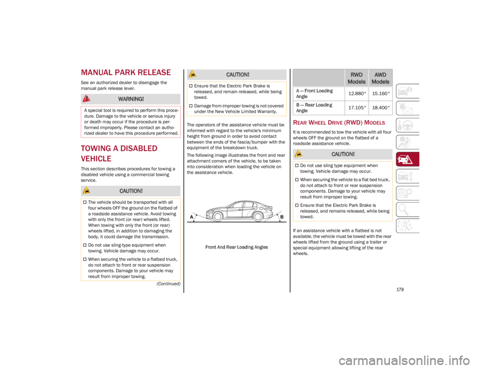
The following image illustrates the front and rear
attachment corners of the vehicle, to be taken
into consideration when loading the vehicle on
the assistance vehicle.
Front And Rear Loading Angles
REAR WHEEL DRIVE (RWD) MODELS
It is recommended to tow the vehicle with all four
wheels OFF the ground on the flatbed of a
roadside assistance vehicle.
If an assistance vehicle with a flatbed is not
available, the vehicle must be towed with the rear
wheels lifted from the ground using a trailer or
special equipment allowing lifting of the rear
wheels.
WARNING!
A special tool is required to perform this proce -
dure. Damage to the vehicle or serious injury
or death may occur if the procedure is per -
formed improperly. Please contact an autho -
rized dealer to have this procedure performed.
CAUTION!
The vehicle should be transported with all
four wheels OFF the ground on the flatbed of
a roadside assistance vehicle. Avoid towing
with only the front (or rear) wheels lifted.
When towing with only the front (or rear)
wheels lifted, in addition to damaging the
body, it could damage the transmission.
Do not use sling-type equipment when
towing. Vehicle damage may occur.
When securing the vehicle to a flatbed truck,
do not attach to front or rear suspension
components. Damage to your vehicle may
result from improper towing.
Ensure that the Electric Park Brake is
released, and remain released, while being
towed.
Damage from improper towing is not covered
under the New Vehicle Limited Warranty.
CAUTION!RWD
ModelsAWD
Models
A — Front Loading
Angle 12.880° 15.160°
B — Rear Loading
Angle 17.105° 18.400°
CAUTION!
Do not use sling type equipment when
towing. Vehicle damage may occur.
When securing the vehicle to a flat bed truck,
do not attach to front or rear suspension
components. Damage to your vehicle may
result from improper towing.
Ensure that the Electric Park Brake is
released, and remains released, while being
towed.
22_GA_OM_EN_USC_t.book Page 179
Page 182 of 248

IN CASE OF EMERGENCY
180
(Continued)
ALL WHEEL DRIVE (AWD) MODELS
It is recommended to tow the vehicle with all four
wheels OFF the ground on the flatbed of a
roadside assistance vehicle.
TOW EYES
If the vehicle has been in an accident or has
broken down, a tow eye is provided in the tools
container located inside the luggage
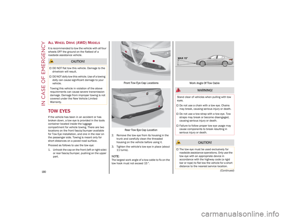
compartment for vehicle towing. There are two
locations on the front fascia/bumper available
for Tow Eye installation, and one in the rear on
the passenger side. Towing is meant only for
short distances on a paved road surface.
Proceed as follows to use the tow eye:
1. Unhook the cap on the front (left or right side)or rear fascia/bumper, pushing on the upper
part. Front Tow Eye Cap Locations
Rear Tow Eye Cap Location
2. Remove the tow eye from its housing in the trunk and carefully clean the threaded
housing on the vehicle before using it.
3. Tighten the vehicle's tow eye in place (about 11 turns).
NOTE:
The largest work angle of a tow cable to fix on the
tow hook must not exceed 15°. Work Angle Of Tow Cable
CAUTION!
DO NOT flat tow this vehicle. Damage to the
drivetrain will result.
DO NOT dolly tow this vehicle. Use of a towing
dolly can cause significant damage to your
vehicle.
Towing this vehicle in violation of the above
requirements can cause severe transmission
damage. Damage from improper towing is not
covered under the New Vehicle Limited
Warranty.
WARNING!
Stand clear of vehicles when pulling with tow
eyes.
Do not use a chain with a tow eye. Chains
may break, causing serious injury or death.
Do not use a tow strap with a tow eye. Tow
straps may break or become disengaged,
causing serious injury or death.
Failure to follow proper tow eye usage may
cause components to break resulting in
serious injury or death.
CAUTION!
The tow eye must be used exclusively for
roadside assistance operations. Only use the
tow eye with an appropriate device in
accordance with the highway code (a rigid
bar or rope) to flat tow the vehicle for a short
distance to the nearest service location.
22_GA_OM_EN_USC_t.book Page 180