2022 ACURA MDX height
[x] Cancel search: heightPage 206 of 712

Continued205
uuSeats uHead Restraints
Controls
Head restraints can be removed for cleaning or repair.
To remove a head restraint:
Pull the restraint up as far as it will go. Then push the release button, and pull the
restraint up and out.
To reinstall a head restraint:
Insert the legs back in place, then adjust the head restraint to an appropriate height
while pressing the release button. Pull up on the restraint to make sure it is locked
in position.
To remove a head restraint:
Pull the restraint up as far as it will go . Then push the release buttons which are
located on the both legs at the same time, and pull the restraint up and out.
To reinstall a head restraint:
Insert the legs back in place, then adjust the head restraint to an appropriate height
while pressing the right release button. Pull up on the restraint to make sure it is
locked in position.
■Removing and Reinstalling the Head Restraints1 Removing and Reinstalling the Head Restraints
To remove and install the fr ont head restraint, recline
the seat-back slightly forward as the space between
the ceiling and the seat-back is limited.
3WARNING
Failure to reinstall, or correctly reinstall, the
head restraints can result in severe injury
during a crash.
Always replace the he ad restraints before
driving.
Front and second row head restraints
Front and second row outer head restraints
Second row center head restraint
22 ACURA MDX-31TYA6000_02.book 205 ページ 2020年11月5日 木曜日 午前11時39分
Page 418 of 712

Continued417
uuBefore Driving uDriving Preparation
Driving
• Store or secure all items on board properly.
u Carrying too much cargo, or improperly storing it, can affect your vehicle’s
handling, stability, sto pping distance, and tires, and make it unsafe.
2Maximum Load Limit P. 419
•Do not pile items higher than the seat height.
u They can block your view and may be thrown forward in the event of sudden
braking.
• Do not place anything in the front seat footwells. Make sure to secure the floor
mat.
u An object or unsecured floor mat can in terfere with your brake and accelerator
pedal operation while driving.
• If you have any animals on board, do not let them move around in the vehicle.
u They may interfere with driv ing and a crash could occur.
• Securely close and lock al l doors and the tailgate.
2Locking/Unlocking the Doors from the Inside P. 143
•Adjust your seating position properly.
u Adjust the head restraint, too.
2Seats P. 190
2 Adjusting the Front and Second Row Outer Head Restraint Positions P. 202
•Adjust the mirrors and steering wheel properly.
u Adjust them while sitting in the proper driving position.
2 Adjusting the Steering Wheel P. 186
2 Mirrors P. 187
■Interior Checks1Interior Checks
The headlight aim is set by the factory, and does not
need to be adjusted. Howeve r, if you regularly carry
heavy items in the cargo area or tow a trailer, have
the aiming readjusted at a dealer or by a qualified
technician.
22 ACURA MDX-31TYA6000_02.book 417 ページ 2020年11月5日 木曜日 午前11時39分
Page 428 of 712

Continued427
uuTowing a Trailer uTowing Preparation
Driving
■Trailer light
Trailer lights and equipment must comply with federal, state, province/territory, and
local regulations. Check with your local trailer sales or rental agency for the
requirements in the area where you plan to tow.
We recommend that you have a dealer inst all a Acura wiring harness and converter.
They are designed for your vehicle.
■Hitches
Read the trailer manufacturer ’s instructions, and select the appropriate draw bar for
the height of the trailer you will be towing.
■Weight distribution hitches
Your vehicle is designed to tow without the need for a load distributing hitch. If you
wish to use one, please cons ult your trailer maker for proper installation and set-up.
Improper set-up could degrade the handling, stability, and braking performance of
your vehicle.
1 Trailer light
The trailer lighting connect or is located behind the
rear panel lining in the cargo area.
Even if you are planning to use the non-Acura trailer
lighting harness and converte r, ask a dealer for the
correct connector and pins.
Brake Diag
Pins’ wiring color codes and their purposes:
+B Back Up
Carg o L
i
ght
Rear Left Welcome
Light
Ground
Interior Light Cut
Relay Out 2
Hands Free Access
Signal
Right Small Light
Right Turn Signal +B Trailer Back Light
+B Trailer Small Light
+B Trailer Hazard Light
+B Trailer Charge
Electric Brake
Back Light
IG2 A/C
Left Turn Signal
22 ACURA MDX-31TYA6000_02.book 427 ページ 2020年11月5日 木曜日 午前11時39分
Page 453 of 712

452
uuWhen Driving uAcura Integrated Dynamics System
Driving
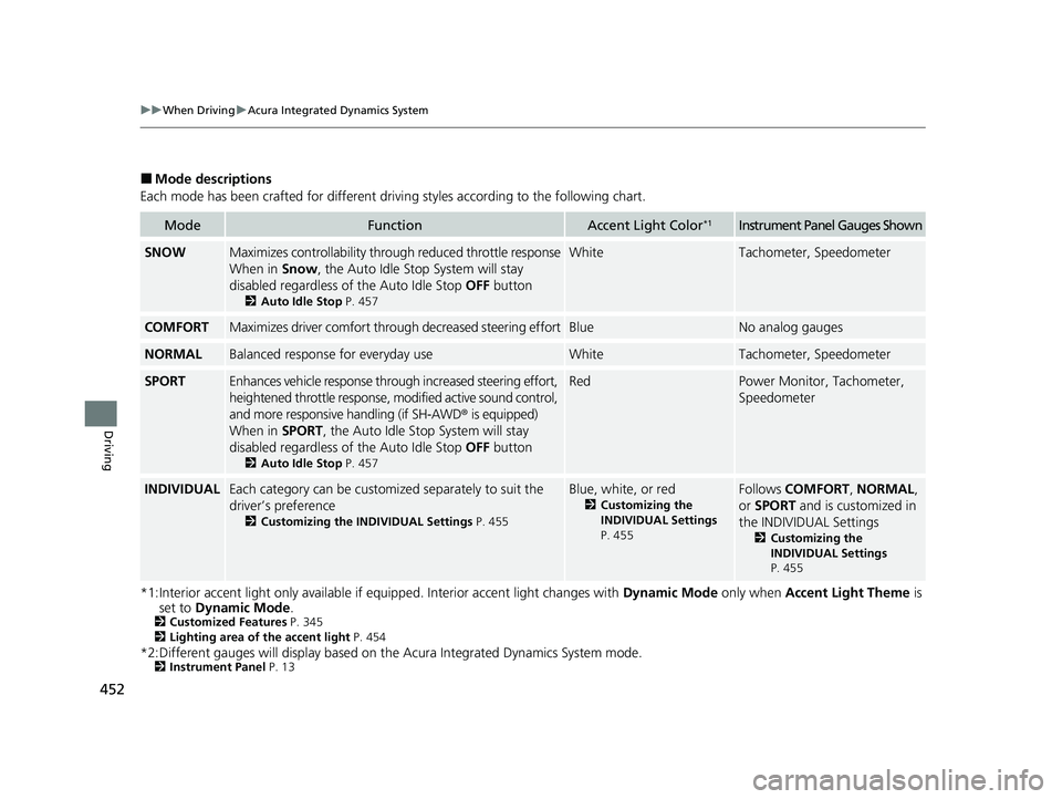
■Mode descriptions
Each mode has been crafted for different driving styles according to the following chart.
*1:Interior accent light only available if equipped. Interior accent light changes with Dynamic Mode only when Accent Light Theme is
set to Dynamic Mode .
2Customized Features P. 345
2 Lighting area of the accent light P. 454
*2:Different gauges will display based on th e Acura Integrated Dynamics System mode.2Instrument Panel P. 13
ModeFunctionAccent Light Color*1Instrument Panel Gauges Shown
SNOWMaximizes controllability thr ough reduced throttle response
When in Snow, the Auto Idle Stop System will stay
disabled regardless of the Auto Idle Stop OFF button
2Auto Idle Stop P. 457
WhiteTachometer, Speedometer
COMFORTMaximizes driver comfort through decreased steering effortBlueNo analog gauges
NORMALBalanced response for everyday useWhiteTachometer, Speedometer
SPORTEnhances vehicle response thro ugh increased steering effort,
heightened throttle response, mo dified active sound control,
and more responsive handling (if SH-AWD® is equipped)
When in SPORT, the Auto Idle Stop System will stay
disabled regardless of the Auto Idle Stop OFF button
2Auto Idle Stop P. 457
RedPower Monitor, Tachometer,
Speedometer
INDIVIDUALEach category can be customized separately to suit the
driver’s preference
2Customizing the INDIVIDUAL Settings P. 455
Blue, white, or red
2Customizing the
INDIVIDUAL Settings
P. 455
Follows COMFORT , NORMAL ,
or SPORT and is customized in
the INDIVIDUAL Settings
2 Customizing the
INDIVIDUAL Settings
P. 455
22 ACURA MDX-31TYA6000_02.book 452 ページ 2020年11月5日 木曜日 午前11時39分
Page 488 of 712

487
uuAcuraWatchTMuCollision Mitigation Braking SystemTM (CMBSTM)
Continued
Driving
• When there is a group of people in front of your vehicle walking together side by
side.
• Surrounding conditions or belongings of the pedestrian alter the pedestrian’s
shape, preventing the system from recogn izing that the person is a pedestrian.
• When the pedestrian is slouching or squatting.
• When the pedestrian is shorte r than about 3.3 feet (1 meter) or taller than about
6.6 feet (2 meter) in height.
• When a pedestrian blends in with the background.
• When a pedestrian is bent over or squatting, or when their hands are raised or
they are running.
• When several pedestrians are walking ahead in a group.
• When the camera cannot correctly identify that a pedestrian is present due to an
unusual shape (holding luggage, body position, size).
■Automatic shutoff
The CMBSTM may automatically shut itself off and the safety support indicator
(amber) comes and stays on when:
• The temperature inside the system is high.
• You drive off-road or on a mountain road, or curved and winding road for an
extended period.
• An abnormal tire condition is detected (wrong tire size, flat tire, etc.).
• The camera behind the rearview mirror, or the area around the camera, including
the windshield, gets dirty.
Once the conditions that caused CMBS
TM to shut off improve or are addressed (e.g.,
cleaning), the system comes back on.
Limitations applicable to pedestrian detection only
22 ACURA MDX-31TYA6000_02.book 487 ページ 2020年11月5日 木曜日 午前11時39分
Page 577 of 712

uuSurround View Camera System*u
576
Driving
Following can be displayed when the system is on.
Guide lines: Help you to get a sense of a distance between your vehicle and the
rear surroundings. The distan ce may appear differently than the actual distance.
Projection lines : Indicate vehicle direction while the steering wheel is in the current
position.
■Reference Lines and Guides1 Reference Lines and Guides
The positions/distances indi cated by the guide lines
and camera views on the display may differ from the
actual positions/distances due to the changes in the
vehicle height, road conditions, and other factors.
The guide lines should be used as a reference only.
The guide lines can be tu rned on and off using the
audio/information screen.
2 Customized Features P. 345
If you turn the guide lines off, they remain off until
you turn them back on.
22 ACURA MDX-31TYA6000_02.book 576 ページ 2020年11月5日 木曜日 午前11時39分
Page 597 of 712

596
uuMaintenance Under the Hood uOpening the Hood
Maintenance
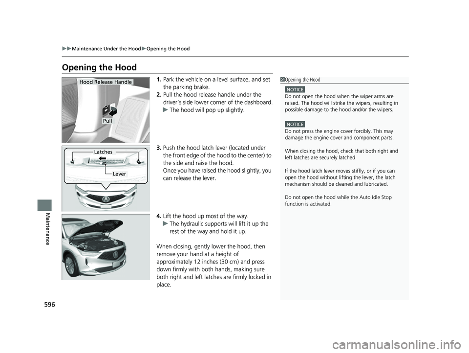
Opening the Hood
1. Park the vehicle on a level surface, and set
the parking brake.
2. Pull the hood release handle under the
driver’s side lower co rner of the dashboard.
u The hood will pop up slightly.
3. Push the hood latch lever (located under
the front edge of the hood to the center) to
the side and raise the hood.
Once you have raised the hood slightly, you
can release the lever.
4. Lift the hood up most of the way.
u The hydraulic supports will lift it up the
rest of the way and hold it up.
When closing, gently lower the hood, then
remove your hand at a height of
approximately 12 inches (30 cm) and press
down firmly with both hands, making sure
both right and left latche s are firmly locked in
place.1 Opening the Hood
NOTICE
Do not open the hood when the wiper arms are
raised. The hood will strike the wipers, resulting in
possible damage to the hood and/or the wipers.
NOTICE
Do not press the engine cover forcibly. This may
damage the engine cover and component parts.
When closing the hood, check that both right and
left latches are securely latched.
If the hood latch lever moves stiffly, or if you can
open the hood without lifti ng the lever, the latch
mechanism should be cl eaned and lubricated.
Do not open the hood while the Auto Idle Stop
function is activated.
Hood Release Handle
Pull
Lever
Latches
22 ACURA MDX-31TYA6000_02.book 596 ページ 2020年11月5日 木曜日 午前11時39分
Page 617 of 712

616
uuChecking and Maintaining Tires uTire and Loading Information Label
Maintenance
Tire and Loading Information Label
The label attached to the driver’s doorj amb provides necessary tire and loading
information.
Tire Labeling
The tires that came on your vehicle have a
number of markings. Those you should be
aware of are described as shown.
Whenever tires are replaced, they should be replaced with tires of the same size.
1 Tire and Loading Information Label
The tire and loading informat ion label attached to the
driver’s doorjamb contains:
aThe number of people your vehicle can carry.
bThe total weight your vehicle can carry. Do not
exceed this weight.
cThe original tire sizes for front, rear, and spare.
dThe proper cold tire pressure for front, rear, and
spare.
Label
Example
Example Tire Size
Tire
Identification
Number (TIN)
Maximum
Tire Load
Maximum
Tire Pressure
Tire Size
■Tire Sizes
1 Tire Sizes
Following is an example of tire size with an
explanation of what each component means.
P235/60R18 102V
P: Vehicle type (P indi cates passenger vehicle).
235: Tire width in millimeters.
60: Aspect ratio (the tire’s section height as a
percentage of its width).
R: Tire construction code (R indicates radial).
18: Rim diameter in inches.
102: Load index (a numerical code associated with
the maximum load the tire can carry).
V: Speed symbol (an alphab etical code indicating the
maximum speed rating).
22 ACURA MDX-31TYA6000_02.book 616 ページ 2020年11月5日 木曜日 午前11時39分