Page 64 of 94

Periodic maintenance an d a djustment
6-20
6
EAU33893
A djustin g the clutch lever free
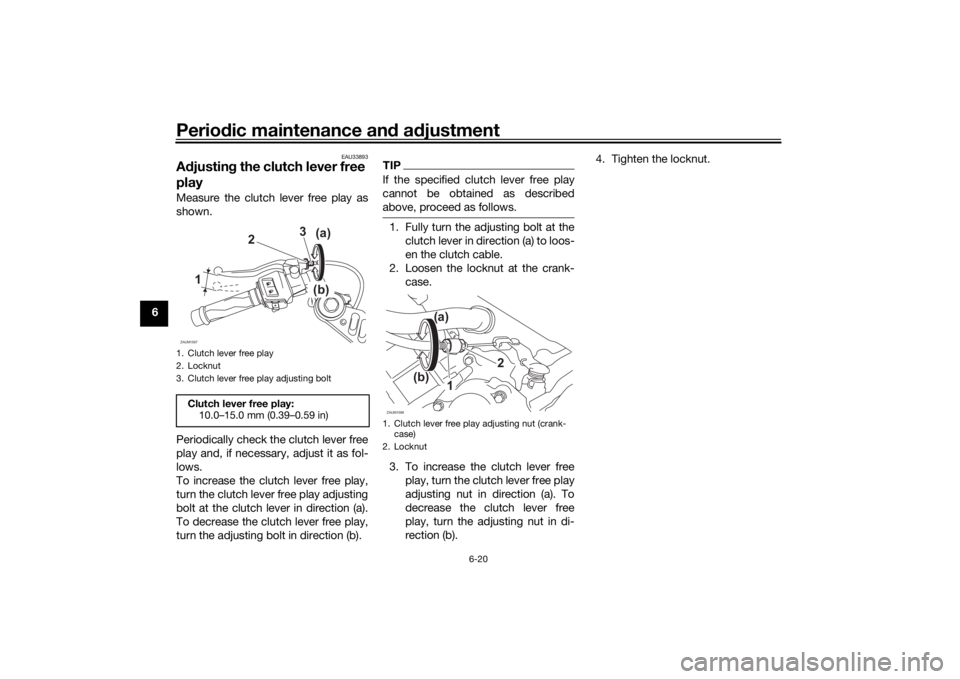
playMeasure the clutch lever free play as
shown.
Periodically check the clutch lever free
play and, if necessary, adjust it as fol-
lows.
To increase the clutch lever free play,
turn the clutch lever free play adjusting
bolt at the clutch lever in direction (a).
To decrease the clutch lever free play,
turn the adjusting bolt in direction (b).
TIPIf the specified clutch lever free play
cannot be obtained as described
above, proceed as follows.1. Fully turn the adjusting bolt at the
clutch lever in direction (a) to loos-
en the clutch cable.
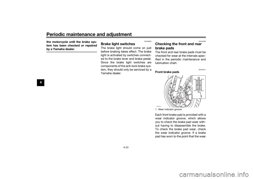
2. Loosen the locknut at the crank- case.
3. To increase the clutch lever free play, turn the clutch lever free play
adjusting nut in direction (a). To
decrease the clutch lever free
play, turn the adjusting nut in di-
rection (b). 4. Tighten the locknut.
1. Clutch lever free play
2. Locknut
3. Clutch lever free play adjusting boltClutch lever free play:
10.0–15.0 mm (0.39–0.59 in)ZAUM1597
)
)
3
2
1 (a
(b
1. Clutch lever free play adjusting nut (crank- case)
2. LocknutZAUM1598
2
(a)
(b) 1
UB5GE2E0.book Page 20 Thursday, July 30, 2020 3:08 PM
Page 66 of 94

Periodic maintenance an d a djustment
6-22
6 the motorcycle until the
brake sys-
tem has b een checked or repaired
b y a Yamaha dealer.
EAU36505
Brake li ght switchesThe brake light should come on just
before braking takes effect. The brake
light is activated by switches connect-
ed to the brake lever and brake pedal.
Since the brake light switches are
components of the anti-lock brake sys-
tem, they should only be serviced by a
Yamaha dealer.
EAU22393
Checkin g the front an d rear
b rake pa dsThe front and rear brake pads must be
checked for wear at the intervals spec-
ified in the periodic maintenance and
lubrication chart.
EAU22421
Front brake pa ds
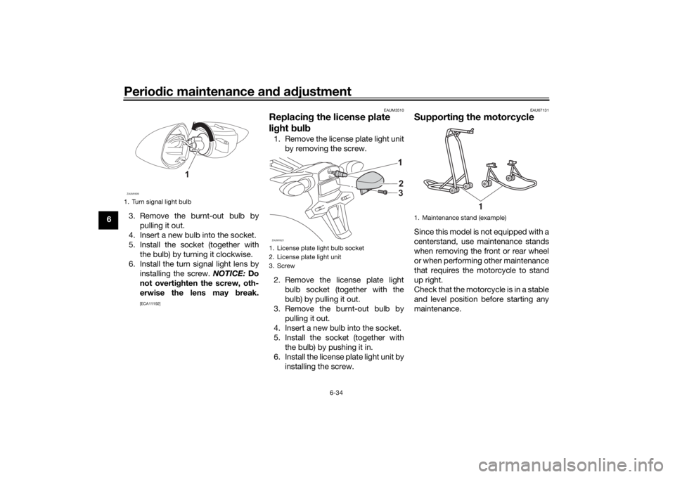
Each front brake pad is provided with a
wear indicator groove, which allows
you to check the brake pad wear with-
out having to disassemble the brake.
To check the brake pad wear, check
the wear indicator groove. If a brake
pad has worn to the point that the wear1. Wear indicator grooveZAUM1466
1
UB5GE2E0.book Page 22 Thursday, July 30, 2020 3:08 PM
Page 68 of 94

Periodic maintenance an d a djustment
6-24
6
Use only the specified b rake flu-
i d ; otherwise, the ru bber seals
may deteriorate, causin g leak-
a g e.
Refill with the same type of
brake flui d. A ddin g a brake flui d
other than DOT 4 may result in a
harmful chemical reaction.
Be careful that water or d ust
d oes not enter the brake flui d
reservoir when refillin g. Water
will si gnificantly lower the boil-
in g point of the flui d an d may re-
sult in vapor lock, an d d irt may
clo g the ABS hy draulic unit
valves.
NOTICE
ECA17641
Brake flui d may damag e painted
surfaces or plastic parts. Always
clean up spille d flui d imme diately.As the brake pads wear, it is normal for
the brake fluid level to gradually go
down. A low brake fluid level may indi-
cate worn brake pads and/or brake
system leakage; therefore, be sure to
check the brake pads for wear and the
brake system for leakage. If the brake fluid level goes down suddenly, have a
Yamaha dealer check the cause before further riding.
EAU22734
Chan gin g the brake flui dHave a Yamaha dealer change the
brake fluid every 2 years. In addition,
have the seals of the master cylinders
and brake calipers, as well as the brake
hoses replaced at the intervals listed
below or sooner if they are damaged or
leaking.
Brake seals: every 2 years
Brake hoses: every 4 years
UB5GE2E0.book Page 24 Thursday, July 30, 2020 3:08 PM
Page 69 of 94

Periodic maintenance an d a djustment
6-25
6
EAU22762
Drive chain slackThe drive chain slack should be
checked before each ride and adjusted
if necessary.
EAU74253
To check the drive chain slack
1. Place the motorcycle on the side- stand.TIPWhen checking and adjusting the drive
chain slack, there should be no weight
on the motorcycle.2. Shift the transmission into the neutral position.
3. Measure the drive chain slack as shown. 4. If the drive chain slack is incorrect,
adjust it as follows. NOTICE: Im-
proper drive chain slack will
overloa d the en gine as well as
other vital parts of the motorcy-
cle an d can lead to chain slip-
pa ge or b reakag e. To prevent
this from occurrin g, keep the
d rive chain slack within the
specifie d limits.
[ECA10572]
EAU3431B
To adjust the drive chain slack
Consult a Yamaha dealer before ad-
justing the drive chain slack. 1. Loosen the axle nut and the lock- nut on each side of the swingarm. 2. To tighten the drive chain, turn the
drive chain slack adjusting bolt on
each side of the swingarm in di-
rection (a). To loosen the drive
chain, turn the adjusting bolt on
each side of the swingarm in di-
rection (b), and then push the rear
wheel forward.
TIPUsing the alignment marks on each
side of the swingarm, make sure that
both drive chain pullers are in the same
position for proper wheel alignment.
1. Drive chain slackZAUM1604
1
Drive chain slack:30.0–40.0 mm (1.18–1.57 in)
1. Drive chain slack adjusting bolt
2. Axle nut
3. Alignment marks
4. LocknutZAUM1605
321
4
(b)
(a)
UB5GE2E0.book Page 25 Thursday, July 30, 2020 3:08 PM
Page 70 of 94

Periodic maintenance an d a djustment
6-26
6 3. Tighten the axle nut, then the lock-
nuts to their specified torques.
4. Make sure that the drive chain pullers are in the same position,
the drive chain slack is correct,
and the drive chain moves
smoothly.
EAU23026
Cleanin g an d lu bricatin g the
d rive chainThe drive chain must be cleaned and
lubricated at the intervals specified in
the periodic maintenance and lubrica-
tion chart, otherwise it will quickly wear
out, especially when riding in dusty or
wet areas. Service the drive chain as
follows.NOTICE
ECA10584
The drive chain must b e lubricated
after washin g the motorcycle, ri din g
in the rain or ri din g in wet areas.1. Clean the drive chain with kero-
sene and a small soft brush.
NOTICE: To prevent d amaging
the O-rin gs, do not clean the
d rive chain with steam cleaners,
hi gh-pressure washers or inap-
propriate solvents.
[ECA11122]
2. Wipe the drive chain dry.
3. Thoroughly lubricate the drive chain with a special O-ring chain
lubricant. NOTICE: Do not use
en gine oil or any other lu bri-
cants for the drive chain, as they may contain su
bstances that
coul d damag e the O-rin gs.
[ECA11112]
Ti ghtenin g torques:
Axle nut: 85 N·m (8.5 kgf·m, 63 lb·ft)
Locknut:
15 N·m (1.5 kgf·m, 11 lb·ft)
UB5GE2E0.book Page 26 Thursday, July 30, 2020 3:08 PM
Page 77 of 94
Periodic maintenance an d a djustment
6-33
6
EAUN2261
Vehicle li ghtsThis model is equipped with LED lights
for headlights, auxiliary lights and
brake/tail light. If a light does not come
on, check the fuse and then have a
Yamaha dealer check the vehicle.NOTICE
ECA16581
Do not affix any type of tinte d film or
stickers to the head lig ht lens.
EAU24182
Tail/b rake li ghtThis model is equipped with an LED-
type tail/brake light.
If the tail/brake light does not come on,
have a Yamaha dealer check it.
EAU62590
Replacin g a turn sig nal light
b ul b1. Remove the turn signal light lens
by removing the screw.
2. Remove the turn signal light bulb socket (together with the bulb) by
turning it counterclockwise.
1. Auxiliary light
2. Headlight (high beam)
3. Headlight (low beam)ZAUM1622
231
1. Screw
1
UB5GE2E0.book Page 33 Thursday, July 30, 2020 3:08 PM
Page 78 of 94

Periodic maintenance an d a djustment
6-34
6 3. Remove the burnt-out bulb by
pulling it out.
4. Insert a new bulb into the socket.
5. Install the socket (together with the bulb) by turning it clockwise.
6. Install the turn signal light lens by installing the screw. NOTICE: Do
not overti ghten the screw, oth-
erwise the lens may break.
[ECA11192] EAUM3510
Replacin
g the license plate
li g ht bul b1. Remove the license plate light unit
by removing the screw.
2. Remove the license plate light bulb socket (together with the
bulb) by pulling it out.
3. Remove the burnt-out bulb by pulling it out.
4. Insert a new bulb into the socket.
5. Install the socket (together with the bulb) by pushing it in.
6. Install the license plate light unit by installing the screw.
EAU67131
Supportin g the motorcycleSince this model is not equipped with a
centerstand, use maintenance stands
when removing the front or rear wheel
or when performing other maintenance
that requires the motorcycle to stand
up right.
Check that the motorcycle is in a stable
and level position before starting any
maintenance.
1. Turn signal light bulbZAUM1609
1
1. License plate light bulb socket
2. License plate light unit
3. ScrewZAUM1621
2
3
1. Maintenance stand (example)
1
UB5GE2E0.book Page 34 Thursday, July 30, 2020 3:08 PM
Page 81 of 94

Periodic maintenance an d a djustment
6-37
6
EAU86420
En gine overheatin g
WARNING
EWAT1041
Do not remove the ra diator cap when the en gine an d ra diator are hot. Scal din g hot flui d an d steam may be
b lown out un der pressure, which coul d cause serious injury. Be sure to wait until the en gine has coole d.
Place a thick ra g, like a towel, over the ra diator cap, an d then slowly rotate the cap counterclockwise to the
d etent to allow any resi dual pressure to escape. When the hissin g soun d has stoppe d, press down on the cap
while turnin g it counterclockwise, an d then remove the cap.TIPIf coolant is not available, tap water can be temporarily used instead, provided that it is changed to the recommended cool-
ant as soon as possible.
Wait until the
engine has cooled.
Check the coolant level in the
reservoir and radiator.
The coolant level
is OK.The coolant level is low.
Check the cooling system
for leakage.
Have a Yamaha dealer checkand repair the cooling system.Add coolant. (See TIP.)
Start the engine. If the engine overheats again,
have a
Yamaha dealer check
and repair the cooling system.
There is
leakage.
There is
no leakage.
UB5GE2E0.book Page 37 Thursday, July 30, 2020 3:08 PM