2021 YAMAHA YZF-R125 Rear
[x] Cancel search: RearPage 69 of 94

Periodic maintenance an d a djustment
6-25
6
EAU22762
Drive chain slackThe drive chain slack should be
checked before each ride and adjusted
if necessary.
EAU74253
To check the drive chain slack
1. Place the motorcycle on the side- stand.TIPWhen checking and adjusting the drive
chain slack, there should be no weight
on the motorcycle.2. Shift the transmission into the neutral position.
3. Measure the drive chain slack as shown. 4. If the drive chain slack is incorrect,
adjust it as follows. NOTICE: Im-
proper drive chain slack will
overloa d the en gine as well as
other vital parts of the motorcy-
cle an d can lead to chain slip-
pa ge or b reakag e. To prevent
this from occurrin g, keep the
d rive chain slack within the
specifie d limits.
[ECA10572]
EAU3431B
To adjust the drive chain slack
Consult a Yamaha dealer before ad-
justing the drive chain slack. 1. Loosen the axle nut and the lock- nut on each side of the swingarm. 2. To tighten the drive chain, turn the
drive chain slack adjusting bolt on
each side of the swingarm in di-
rection (a). To loosen the drive
chain, turn the adjusting bolt on
each side of the swingarm in di-
rection (b), and then push the rear
wheel forward.
TIPUsing the alignment marks on each
side of the swingarm, make sure that
both drive chain pullers are in the same
position for proper wheel alignment.
1. Drive chain slackZAUM1604
1
Drive chain slack:30.0–40.0 mm (1.18–1.57 in)
1. Drive chain slack adjusting bolt
2. Axle nut
3. Alignment marks
4. LocknutZAUM1605
321
4
(b)
(a)
UB5GE2E0.book Page 25 Thursday, July 30, 2020 3:08 PM
Page 73 of 94

Periodic maintenance an d a djustment
6-29
6
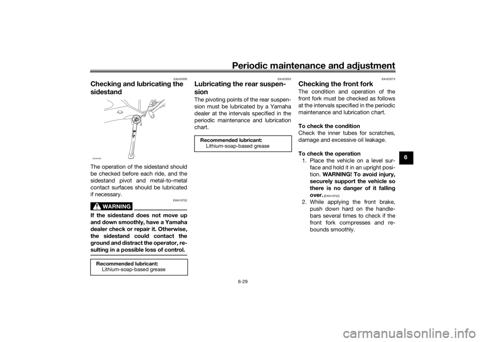
EAU23203
Checkin g an d lu bricatin g the
si destan dThe operation of the sidestand should
be checked before each ride, and the
sidestand pivot and metal-to-metal
contact surfaces should be lubricated
if necessary.
WARNING
EWA10732
If the sid estand d oes not move up
an d d own smoothly, have a Yamaha
d ealer check or repair it. Otherwise,
the si destan d coul d contact the
g roun d an d d istract the operator, re-
sultin g in a possi ble loss of control.
EAU23252
Lu bricatin g the rear suspen-
sionThe pivoting points of the rear suspen-
sion must be lubricated by a Yamaha
dealer at the intervals specified in the
periodic maintenance and lubrication
chart.
EAU23273
Checkin g the front forkThe condition and operation of the
front fork must be checked as follows
at the intervals specified in the periodic
maintenance and lubrication chart.
To check the con dition
Check the inner tubes for scratches,
damage and excessive oil leakage.
To check the operation 1. Place the vehicle on a level sur- face and hold it in an upright posi-
tion. WARNING! To avoi d injury,
securely support the vehicle so
there is no dan ger of it fallin g
over.
[EWA10752]
2. While applying the front brake, push down hard on the handle-
bars several times to check if the
front fork compresses and re-
bounds smoothly.
Recommen ded lu bricant:
Lithium-soap-based greaseZAUM1620
Recommen ded lu bricant:
Lithium-soap-based grease
UB5GE2E0.book Page 29 Thursday, July 30, 2020 3:08 PM
Page 74 of 94

Periodic maintenance an d a djustment
6-30
6
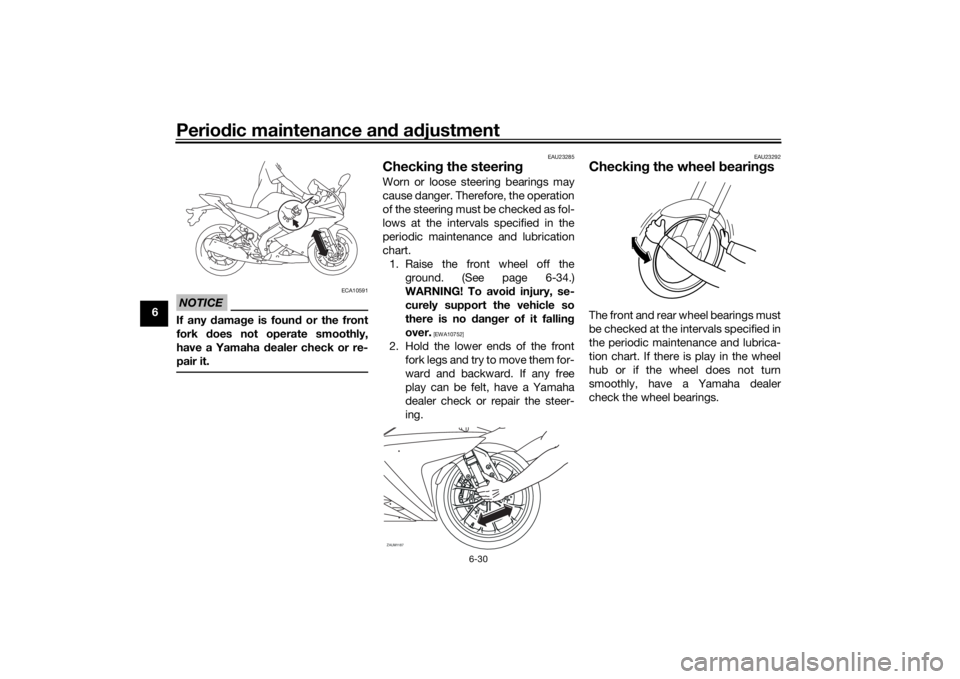
NOTICE
ECA10591
If any d amage is foun d or the front
fork does not operate smoothly,
have a Yamaha d ealer check or re-
pair it.
EAU23285
Checkin g the steerin gWorn or loose steering bearings may
cause danger. Therefore, the operation
of the steering must be checked as fol-
lows at the intervals specified in the
periodic maintenance and lubrication
chart.
1. Raise the front wheel off the ground. (See page 6-34.)
WARNING! To avoi d injury, se-
curely support the vehicle so
there is no dan ger of it fallin g
over.
[EWA10752]
2. Hold the lower ends of the front fork legs and try to move them for-
ward and backward. If any free
play can be felt, have a Yamaha
dealer check or repair the steer-
ing.
EAU23292
Checkin g the wheel bearin gsThe front and rear wheel bearings must
be checked at the intervals specified in
the periodic maintenance and lubrica-
tion chart. If there is play in the wheel
hub or if the wheel does not turn
smoothly, have a Yamaha dealer
check the wheel bearings.
ZAUM1187
UB5GE2E0.book Page 30 Thursday, July 30, 2020 3:08 PM
Page 78 of 94

Periodic maintenance an d a djustment
6-34
6 3. Remove the burnt-out bulb by
pulling it out.
4. Insert a new bulb into the socket.
5. Install the socket (together with the bulb) by turning it clockwise.
6. Install the turn signal light lens by installing the screw. NOTICE: Do
not overti ghten the screw, oth-
erwise the lens may break.
[ECA11192] EAUM3510
Replacin
g the license plate
li g ht bul b1. Remove the license plate light unit
by removing the screw.
2. Remove the license plate light bulb socket (together with the
bulb) by pulling it out.
3. Remove the burnt-out bulb by pulling it out.
4. Insert a new bulb into the socket.
5. Install the socket (together with the bulb) by pushing it in.
6. Install the license plate light unit by installing the screw.
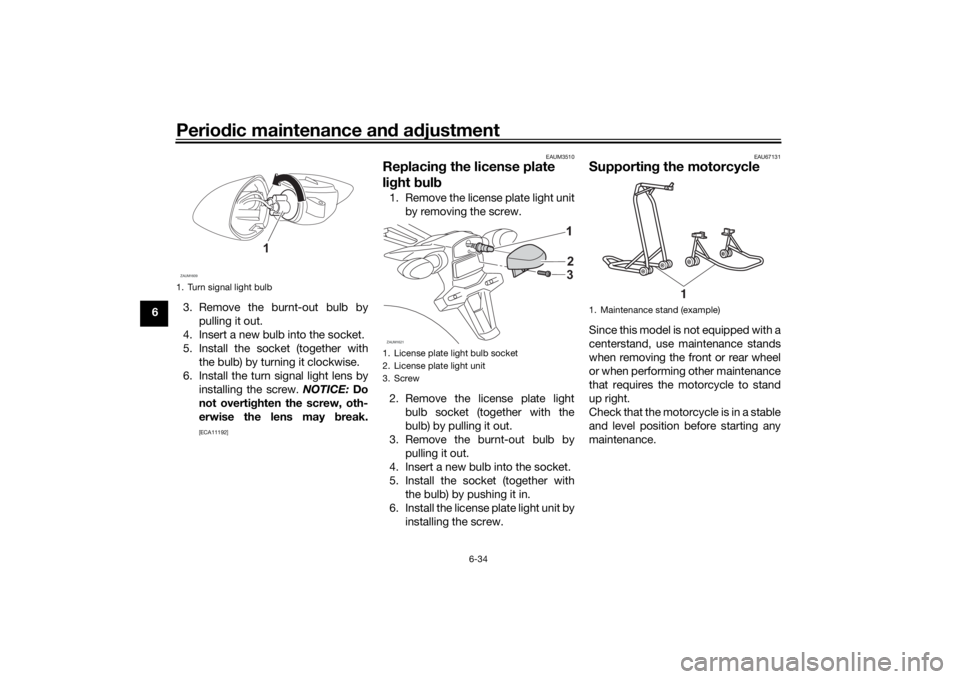
EAU67131
Supportin g the motorcycleSince this model is not equipped with a
centerstand, use maintenance stands
when removing the front or rear wheel
or when performing other maintenance
that requires the motorcycle to stand
up right.
Check that the motorcycle is in a stable
and level position before starting any
maintenance.
1. Turn signal light bulbZAUM1609
1
1. License plate light bulb socket
2. License plate light unit
3. ScrewZAUM1621
2
3
1. Maintenance stand (example)
1
UB5GE2E0.book Page 34 Thursday, July 30, 2020 3:08 PM
Page 86 of 94

Specifications
8-1
8
Dimensions:Overall length:1990 mm (78.3 in)
Overall width:
755 mm (29.7 in)
Overall height: 1140 mm (44.9 in)
Seat height: 820 mm (32.3 in)
Wheelbase:
1325 mm (52.2 in)
Ground clearance: 160 mm (6.30 in)
Minimum turning radius: 2.9 m (9.51 ft)Wei ght:Curb weight:
144 kg (319 lb)Engine:Combustion cycle:
4-stroke
Cooling system: Liquid cooled
Valve train: SOHC
Number of cylinders:
Single cylinder
Displacement: 124 cm³
Bore × stroke:
52.0 × 58.6 mm (2.05 × 2.31 in)
Starting system:
Electric starter
Engine oil:Recommended brand:
SAE viscosity grades:
10W-40
Recommended engine oil grade: API service SG type or higher, JASO
standard MA
Engine oil quantity: Oil change: 0.85 L (0.90 US qt, 0.75 Imp.qt)
With oil filter removal: 0.95 L (1.00 US qt, 0.84 Imp.qt)Coolant quantity:Coolant reservoir (up to the maximum level
mark):
0.15 L (0.16 US qt, 0.13 Imp.qt)
Radiator (including all routes): 0.49 L (0.52 US qt, 0.43 Imp.qt)Fuel:Recommended fuel:
Unleaded gasoline (E10 acceptable)
Octane number (RON): 95
Fuel tank capacity: 11 L (2.9 US gal, 2.4 Imp.gal)
Fuel reserve amount:
3.0 L (0.79 US gal, 0.66 Imp.gal)
Fuel injection:Throttle body:ID mark: BK71 00Drivetrain:Gear ratio:
1st:2.833 (34/12)
2nd:
1.875 (30/16)
3rd: 1.364 (30/22)
4th: 1.143 (24/21)
5th:
0.957 (22/23)
6th: 0.840 (21/25)Front tire:Type:
Tubeless
Size: 100/80-17M/C 52S
Manufacturer/model: MICHELIN PILOT STREETRear tire:Type:Tubeless
Size: 140/70-17M/C 66S
Manufacturer/model:
MICHELIN PILOT STREET
UB5GE2E0.book Page 1 Thursday, July 30, 2020 3:08 PM
Page 87 of 94

Specifications
8-2
8
Loadin g:Maximum load:
175 kg (387 lb)
(Total weight of rider, passenger, cargo and
accessories)Front brake:Type:
Hydraulic single disc brakeRear brake:Type:
Hydraulic single disc brakeFront suspension:Type:
Telescopic forkRear suspension:Type:Swingarm (link suspension)Electrical system:System voltage:12 VBattery:Model:
GTZ4V
Voltage, capacity: 12 V, 3.0 Ah (10 HR)Bul b watta ge:Headlight:
LED
Brake/tail light: LED
Front turn signal light: 10.0 W
Rear turn signal light:
10.0 W Auxiliary light:
LED
License plate light: 5.0 W
UB5GE2E0.book Page 2 Thursday, July 30, 2020 3:08 PM
Page 91 of 94

10-1
10
Index
AABS....................................................... 3-15
ABS warning light ................................... 3-3
Air filter element and check hose,
replacing and cleaning ....................... 6-15BBattery .................................................. 6-31
Brake and clutch levers, checking and lubricating........................................... 6-28
Brake and shift pedals, checking and lubricating........................................... 6-27
Brake fluid, changing............................ 6-24
Brake fluid level, checking.................... 6-23
Brake lever............................................ 3-14
Brake light switches ............................. 6-22
Brake pedal .......................................... 3-14
Brake pedal free play, adjusting ........... 6-21CCables, checking and lubricating ......... 6-27
Canister ................................................ 6-10
Care ........................................................ 7-1
Catalytic converter ............................... 3-19
Clutch lever........................................... 3-13
Clutch lever free play, adjusting ........... 6-20
Coolant ................................................. 6-14
Coolant temperature warning light ......... 3-2
Cowlings, removing and installing.......... 6-8DData recording, vehicle........................... 9-2
Diagnostic connector ............................. 9-2
Dimmer/Pass switch............................. 3-13
Drive chain, cleaning and lubricating ... 6-26
Drive chain slack .................................. 6-25
EEngine break-in ...................................... 5-1
Engine idling speed.............................. 6-16
Engine oil and oil filter element ............ 6-11
Engine overheating .............................. 6-37
Engine serial number ............................. 9-1
Engine stop switch............................... 3-13FFront and rear brake pads, checking ... 6-22
Front brake lever free play, checking ... 6-21
Front fork, checking ............................. 6-29
Fuel ...................................................... 3-16
Fuel consumption, tips for reducing ...... 5-4
Fuel tank breather hose and overflow hose ................................................... 3-18
Fuel tank cap........................................ 3-16
Fuses, replacing ................................... 6-32HHandlebar switches ............................. 3-12
High beam indicator light ....................... 3-2
Horn switch .......................................... 3-13IIdentification numbers ........................... 9-1
Ignition circuit cut-off system .............. 3-21
Indicator lights and warning lights ......... 3-2LLicense plate light bulb, replacing ....... 6-34MMain switch/steering lock ...................... 3-1
Maintenance and lubrication, periodic... 6-4
Maintenance, emission control system ................................................. 6-3
Malfunction indicator light (MIL)............. 3-3
Matte color, caution ............................... 7-1 Model label ............................................. 9-1
Multi-function meter unit ........................ 3-4
NNeutral indicator light ............................. 3-2PParking.................................................... 5-4
Part locations.......................................... 2-1RRear suspension, lubricating ................ 6-29SSafety information................................... 1-1
Seats ..................................................... 3-19
Shifting.................................................... 5-3
Shift light ................................................. 3-3
Shift pedal............................................. 3-14
Sidestand.............................................. 3-20
Sidestand, checking and lubricating .... 6-29
Spark plug, checking .............................. 6-9
Specifications ......................................... 8-1
Starting the engine ................................. 5-2
Start switch ........................................... 3-13
Steering, checking ................................ 6-30
Storage ................................................... 7-3
Supporting the motorcycle ................... 6-34TTail/brake light ...................................... 6-33
Throttle grip and cable, checking and
lubricating ........................................... 6-27
Throttle grip free play, adjusting ........... 6-16
Tires ...................................................... 6-17
Tool kit .................................................... 6-2
Troubleshooting .................................... 6-35
Troubleshooting chart........................... 6-36
Turn signal indicator light ....................... 3-2
UB5GE2E0.book Page 1 Thursday, July 30, 2020 3:08 PM