2021 YAMAHA XSR 125 lock
[x] Cancel search: lockPage 60 of 90

Periodic maintenance an d a djustment
6-19
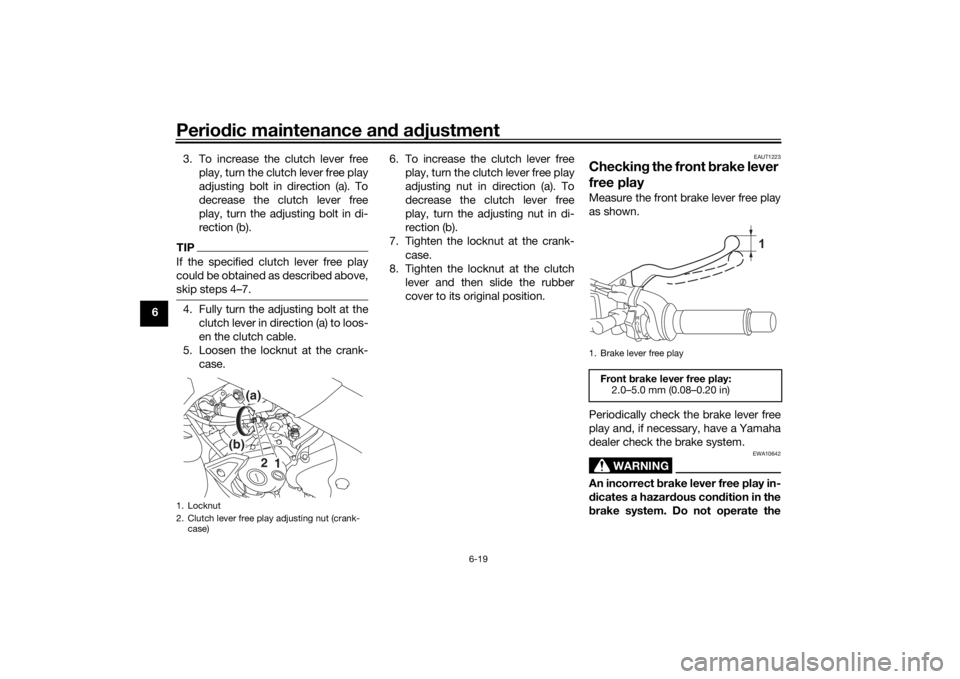
6 3. To increase the clutch lever free
play, turn the clutch lever free play
adjusting bolt in direction (a). To
decrease the clutch lever free
play, turn the adjusting bolt in di-
rection (b).
TIPIf the specified clutch lever free play
could be obtained as described above,
skip steps 4–7.4. Fully turn the adjusting bolt at theclutch lever in direction (a) to loos-
en the clutch cable.
5. Loosen the locknut at the crank- case. 6. To increase the clutch lever free
play, turn the clutch lever free play
adjusting nut in direction (a). To
decrease the clutch lever free
play, turn the adjusting nut in di-
rection (b).
7. Tighten the locknut at the crank- case.
8. Tighten the locknut at the clutch lever and then slide the rubber
cover to its original position.
EAUT1223
Checkin g the front b rake lever
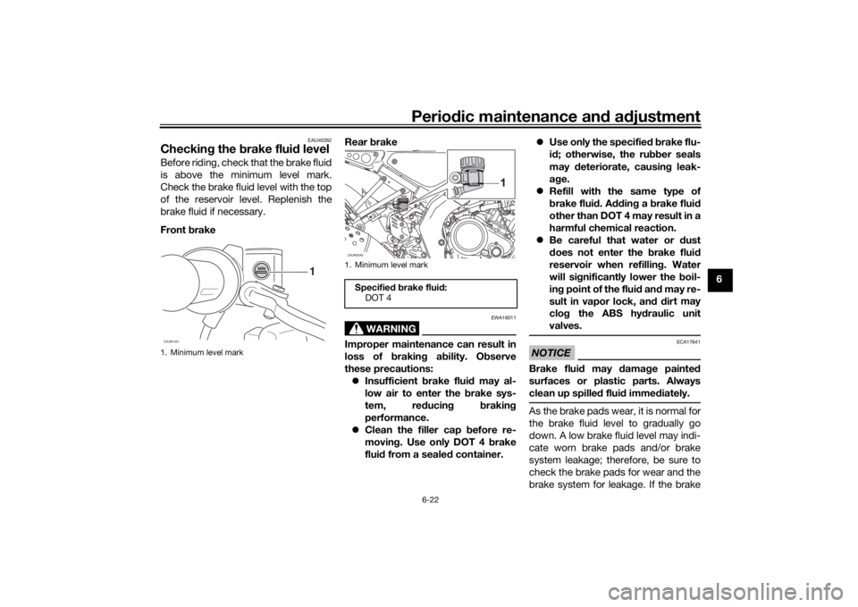
free playMeasure the front brake lever free play
as shown.
Periodically check the brake lever free
play and, if necessary, have a Yamaha
dealer check the brake system.
WARNING
EWA10642
An incorrect b rake lever free play in-
d icates a hazar dous con dition in the
b rake system. Do not operate the
1. Locknut
2. Clutch lever free play adjusting nut (crank-
case)
1
2
(a)
(b)
1. Brake lever free playFront brake lever free play:
2.0–5.0 mm (0.08–0.20 in)
1
UBFGE0E0.book Page 19 Friday, April 9, 2021 9:25 AM
Page 62 of 90

Periodic maintenance an d a djustment
6-21
6
EAU36505
Brake li ght switchesThe brake light should come on just
before braking takes effect. The brake
light is activated by switches connect-
ed to the brake lever and brake pedal.
Since the brake light switches are
components of the anti-lock brake sys-
tem, they should only be serviced by a
Yamaha dealer.
EAU22393
Checkin g the front an d rear
b rake pa dsThe front and rear brake pads must be
checked for wear at the intervals spec-
ified in the periodic maintenance and
lubrication chart.
EAU22434
Front brake pa ds
Each front brake pad is provided with
wear indicator grooves, which allow
you to check the brake pad wear with-
out having to disassemble the brake.
To check the brake pad wear, check
the wear indicator grooves. If a brake
pad has worn to the point that the wear indicator grooves have almost disap-
peared, have a Yamaha dealer replace
the brake pads as a set.
EAU36721
Rear
brake pad s
Each rear brake pad is provided with
wear indicator grooves, which allow
you to check the brake pad wear with-
out having to disassemble the brake.
To check the brake pad wear, check
the wear indicator grooves. If a brake
pad has worn to the point that the wear
indicator grooves have almost disap-
peared, have a Yamaha dealer replace
the brake pads as a set.
1. Wear indicator grooveZAUM2038
1. Wear indicator grooveZAUM2039
1
1
UBFGE0E0.book Page 21 Friday, April 9, 2021 9:25 AM
Page 63 of 90

Periodic maintenance an d a djustment
6-22
6
EAU40262
Checkin g the brake flui d levelBefore riding, check that the brake fluid
is above the minimum level mark.
Check the brake fluid level with the top
of the reservoir level. Replenish the
brake fluid if necessary.
Front brake Rear
brake
WARNING
EWA16011
Improper maintenance can result in
loss of b raking a bility. O bserve
these precautions: Insufficient brake flui d may al-
low air to enter the b rake sys-
tem, re ducin g brakin g
performance.
Clean the filler cap before re-
movin g. Use only DOT 4 b rake
flui d from a seale d container.
Use only the specifie d b rake flu-
i d ; otherwise, the ru bber seals
may deteriorate, causin g leak-
a g e.
Refill with the same type of
brake flui d. A dding a brake flui d
other than DOT 4 may result in a
harmful chemical reaction.
Be careful that water or dust
d oes not enter the brake flui d
reservoir when refilling . Water
will si gnificantly lower the boil-
in g point of the flui d an d may re-
sult in vapor lock, an d d ir
t may
clo g the ABS hy draulic unit
valves.
NOTICE
ECA17641
Brake flui d may damag e painte d
surfaces or plastic parts. Always
clean up spille d flui d imme diately.As the brake pads wear, it is normal for
the brake fluid level to gradually go
down. A low brake fluid level may indi-
cate worn brake pads and/or brake
system leakage; therefore, be sure to
check the brake pads for wear and the
brake system for leakage. If the brake
1. Minimum level mark
1
ZAUM1057
1. Minimum level mark
Specified b rake flui d:
DOT 4ZAUM2040
UBFGE0E0.book Page 22 Friday, April 9, 2021 9:25 AM
Page 65 of 90

Periodic maintenance an d a djustment
6-24
6
4. If the drive chain slack is incorrect,
adjust it as follows. NOTICE: Im-
proper drive chain slack will
overloa d the en gine as well as
other vital parts of the motorcy-
cle an d can lead to chain slip-
pa ge or breakag e. To prevent
this from occurrin g, keep the
d rive chain slack within the
specifie d limits.
[ECA10572]
EAU3431B
To adjust the drive chain slack
Consult a Yamaha dealer before ad-
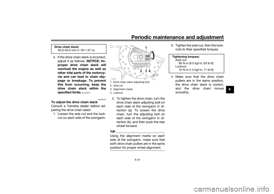
justing the drive chain slack. 1. Loosen the axle nut and the lock- nut on each side of the swingarm. 2. To tighten the drive chain, turn the
drive chain slack adjusting bolt on
each side of the swingarm in di-
rection (a). To loosen the drive
chain, turn the adjusting bolt on
each side of the swingarm in di-
rection (b), and then push the rear
wheel forward.
TIPUsing the alignment marks on each
side of the swingarm, make sure that
both drive chain pullers are in the same
position for proper wheel alignment.
3. Tighten the axle nut, then the lock-nuts to their specified torques.
4. Make sure that the drive chain pullers are in the same position,
the drive chain slack is correct,
and the drive chain moves
smoothly.
Drive chain slack:30.0–40.0 mm (1.18–1.57 in)
1. Drive chain slack adjusting bolt
2. Axle nut
3. Alignment marks
4. LocknutZAUM2042
23 1
4
(b)(a)
Tightenin g torques:
Axle nut: 85 N·m (8.5 kgf·m, 63 lb·ft)
Locknut:
15 N·m (1.5 kgf·m, 11 lb·ft)
UBFGE0E0.book Page 24 Friday, April 9, 2021 9:25 AM
Page 73 of 90

Periodic maintenance an d a djustment
6-32
6
EAUN2261
Vehicle li ghtsThis model is equipped with LED lights
for headlights, auxiliary lights and
brake/tail light. If a light does not come
on, check the fuse and then have a
Yamaha dealer check the vehicle.NOTICE
ECA16581
Do not affix any type of tinte d film or
stickers to the head lig ht lens.
EAU24205
Replacin g a turn sig nal light
b ul b1. Remove the turn signal light lens
by removing the screw.
2. Remove the burnt-out bulb by pushing it in and turning it coun-
terclockwise. 3. Insert a new bulb into the socket,
push it in, and then turn it clock-
wise until it stops.
4. Install the lens by installing the screw. NOTICE: Do not over-
ti ghten the screw, otherwise the
lens may break.
[ECA11192]
1. Auxiliary light
2. Headlight
1
2
1. Turn signal light lens
2. Screw
1
2
1. Turn signal light bulb
1
UBFGE0E0.book Page 32 Friday, April 9, 2021 9:25 AM
Page 77 of 90

Periodic maintenance an d a djustment
6-36
6
EAU86420
En gine overheatin g
WARNING
EWAT1041
Do not remove the ra diator cap when the en gine an d ra diator are hot. Scal din g hot flui d an d steam may be
b lown out un der pressure, which coul d cause serious injury. Be sure to wait until the en gine has coole d.
Place a thick ra g, like a towel, over the ra diator cap, an d then slowly rotate the cap counterclockwise to the
d etent to allow any resi dual pressure to escape. When the hissin g soun d has stoppe d, press down on the cap
while turnin g it counterclockwise, an d then remove the cap.TIPIf coolant is not available, tap water can be temporarily used instead, provided that it is changed to the recommended cool-
ant as soon as possible.
Wait until the
engine has cooled.
Check the coolant level in the
reservoir and radiator.
The coolant level
is OK.The coolant level is low.
Check the cooling system
for leakage.
Have a Yamaha dealer checkand repair the cooling system.Add coolant. (See TIP.)
Start the engine. If the engine overheats again,
have a
Yamaha dealer check
and repair the cooling system.
There is
leakage.
There is
no leakage.
UBFGE0E0.book Page 36 Friday, April 9, 2021 9:25 AM
Page 87 of 90

10-1
10
Index
AABS....................................................... 3-12
ABS warning light ................................... 3-3
Air filter element and check hose,
replacing and cleaning ....................... 6-14BBattery .................................................. 6-30
Brake and clutch levers, checking and lubricating........................................... 6-27
Brake and shift pedals, checking and lubricating........................................... 6-26
Brake fluid, changing............................ 6-23
Brake fluid level, checking.................... 6-22
Brake lever............................................ 3-11
Brake light switches ............................. 6-21
Brake pedal .......................................... 3-11
Brake pedal free play, adjusting ........... 6-20CCables, checking and lubricating ......... 6-25
Canister .................................................. 6-9
Care ........................................................ 7-1
Catalytic converter ............................... 3-16
Clock ...................................................... 3-7
Clutch lever........................................... 3-10
Clutch lever free play, adjusting ........... 6-18
Coolant ................................................. 6-13
Coolant temperature warning light ......... 3-2
Cowlings, removing and installing.......... 6-8DData recording, vehicle........................... 9-2
Diagnostic connector ............................. 9-2
Dimmer switch...................................... 3-10
Display units, switching .......................... 3-4
Drive chain, cleaning and lubricating ... 6-25 Drive chain slack .................................. 6-23
EEngine break-in ...................................... 5-1
Engine idling speed.............................. 6-15
Engine oil and oil filter element ............ 6-10
Engine overheating .............................. 6-36
Engine serial number ............................. 9-1FFront and rear brake pads, checking ... 6-21
Front brake lever free play, checking ... 6-19
Front fork, checking ............................. 6-28
Fuel ...................................................... 3-13
Fuel consumption, tips for reducing ...... 5-4
Fuel meter .............................................. 3-5
Fuel tank breather hose and overflow
hose ................................................... 3-15
Fuel tank cap........................................ 3-13
Fuses, replacing ................................... 6-31HHandlebar switches ............................... 3-9
Helmet holder....................................... 3-17
High beam indicator light ....................... 3-2
Horn switch .......................................... 3-10IIdentification numbers ........................... 9-1
Ignition circuit cut-off system .............. 3-18
Indicator lights and warning lights ......... 3-2LLicense plate light bulb, replacing ....... 6-33MMain switch/steering lock ...................... 3-1
Maintenance and lubrication, periodic... 6-4
Maintenance, emission control system ................................................. 6-3 Malfunction indicator light (MIL) ............. 3-3
Matte color, caution................................ 7-1
Model label ............................................. 9-1
Multi-function display ............................. 3-6
Multi-function meter unit ........................ 3-4
NNeutral indicator light ............................. 3-2PParking.................................................... 5-4
Part locations.......................................... 2-1
Pass switch........................................... 3-10RRear suspension, lubricating ................ 6-28SSafety information................................... 1-1
Seat....................................................... 3-16
Shifting.................................................... 5-3
Shift pedal............................................. 3-11
Sidestand.............................................. 3-17
Sidestand, checking and lubricating .... 6-27
Spark plug, checking .............................. 6-8
Specifications ......................................... 8-1
Speedometer .......................................... 3-4
Start/Engine stop switch ...................... 3-10
Starting the engine ................................. 5-2
Steering, checking ................................ 6-29
Storage ................................................... 7-3
Supporting the motorcycle ................... 6-33
Swingarm pivots, lubricating ................ 6-28TTachometer............................................. 3-5
Throttle grip and cable, checking and
lubricating ........................................... 6-26
Throttle grip free play, adjusting ........... 6-15
UBFGE0E0.book Page 1 Friday, April 9, 2021 9:25 AM