2021 YAMAHA TENERE 700 RALLY EDITION battery
[x] Cancel search: batteryPage 7 of 102

Table of contents
Lubricating the swingarm
pivots .........................................6-29
Checking the front fork..................6-29
Checking the steering ...................6-30
Checking the wheel bearings ........6-30
Battery ...........................................6-31
Replacing the fuses .......................6-32
Vehicle lights .................................6-33
Tail/brake light ...............................6-34
Replacing a turn signal light bulb ............................................6-34
License plate light .........................6-35
Supporting the motorcycle............6-35
Troubleshooting ............................6-36
Troubleshooting chart ...................6-37
Motorcycle care an d stora ge ..........7-1
Matte color caution .........................7-1
Care .................................................7-1
Storage ............................................7-3
Specifications ....................................8-1
Consumer information .....................9-1
Identification numbers .....................9-1
Diagnostic connector ......................9-2
Vehicle data recording ....................9-2
In dex ................................................10-1
UBEHEAE0.book Page 2 Thursday, January 21, 2021 5:45 PM
Page 14 of 102

Description
2-2
2
EAU10421
Right view
1,2
3
4
5
6
1. Main fuse (page 6-32)
2. Fuse box (page 6-32)
3. Battery (page 6-31)
4. Fuel tank cap (page 3-17)
5. Brake pedal (page 3-16)
6. Rear brake fluid reservoir (page 6-22)UBEHEAE0.book Page 2 Thursday, January 21, 2021 5:45 PM
Page 17 of 102

Instrument and control functions
3-2
3
EAU10474
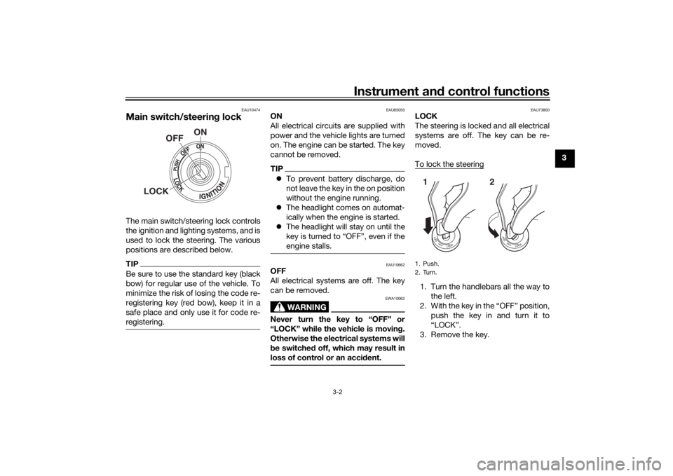
Main switch/steerin g lockThe main switch/steering lock controls
the ignition and lighting systems, and is
used to lock the steering. The various
positions are described below.TIPBe sure to use the standard key (black
bow) for regular use of the vehicle. To
minimize the risk of losing the code re-
registering key (red bow), keep it in a
safe place and only use it for code re-
registering.
EAU85050
ON
All electrical circuits are supplied with
power and the vehicle lights are turned
on. The engine can be started. The key
cannot be removed.TIP To prevent battery discharge, do
not leave the key in the on position
without the engine running.
The headlight comes on automat-
ically when the engine is started.
The headlight will stay on until the
key is turned to “OFF”, even if the
engine stalls.
EAU10662
OFF
All electrical systems are off. The key
can be removed.
WARNING
EWA10062
Never turn the key to “OFF” or
“LOCK” while the vehicle is movin g.
Otherwise the electrical systems will
b e switched off, which may result in
loss of control or an acci dent.
EAU73800
LOCK
The steering is locked and all electrical
systems are off. The key can be re-
moved.
To lock the steering1. Turn the handlebars all the way to
the left.
2. With the key in the “OFF” position, push the key in and turn it to
“LOCK”.
3. Remove the key.
ON
OFF
LOCK
1. Push.
2. Turn.12
UBEHEAE0.book Page 2 Thursday, January 21, 2021 5:45 PM
Page 22 of 102

Instrument and control functions
3-7
3
TIP To switch between kilometers and
miles, set the multi-function dis-
play to the odometer or a tripme-
ter, and then push the top set
button until the display units chan-
ge.
The display units will return to fac-
tory settings in case of battery dis-
connection.
WARNING
EWA12423
Be sure to stop the vehicle b efore
makin g any settin g chan ges to the
multi-function meter unit. Chan gin g
settin gs while ri din g can d istract the
operator an d increase the risk of an
acci dent.Speed ometer
The speedometer shows the vehicle’s
traveling speed. Tachometer
The tachometer shows the engine
speed.
NOTICE
ECA23050
Do not operate the en
gine in the ta-
chometer hi gh-r/min zone.
Hi gh-r/min zone: 9400 r/min and
a b ove
Fuel meter
The fuel meter indicates the amount of
fuel in the fuel tank. The segments of
the fuel meter disappear from “F” (full)
towards “E” (empty) as the fuel level
decreases. When the last segment of
the fuel meter starts flashing, refuel as
soon as possible.TIPIf a problem is detected in the electrical
circuit, the fuel meter segments will
flash repeatedly. If this occurs, have a
Yamaha dealer check the vehicle.
1. Tachometer
2. Tachometer red zone
1 2
1. Fuel meter
1
UBEHEAE0.book Page 7 Thursday, January 21, 2021 5:45 PM
Page 41 of 102

Instrument and control functions
3-26
3
EAU84680
Lu gga ge strap hol dersUse the indicated strap points to se-
cure luggage ties to the vehicle.
EAUM4130
Front fen der To suit the riding conditions, the front
fender height can be adjusted.
To a djust the front fen der hei ght
1. Loosen the bolts on each side of the front fender.
2. Move the front fender to the de- sired height.
3. Tighten the bolts to the specified torque.
EAUM4201
DC power outletsThis vehicle is equiped with an auxiliary
DC jack, and auxiliary DC connector, a
grip warmer connector and a fog lamp
DC connector.NOTICE
ECA26810
Do not use any sin gle electrical ac-
cessory or com bination of accesso-
ries that require more than the
state d capacity at any one time. This
may overloa d the circuit an d cause
the fuse to b low.TIPTo prevent battery drain, do not use an
accessory with the engine off.
1. Luggage strap holder
1
1. Bolt
Tightenin g torque:
Front fender bolt: 7.5 N·m (0.75 kgf·m, 5.6 lb·ft)
1
DC power outlet circuit capacities:
DC jack and DC connector circuit: 24 W (2 A)
Grip warmer and Fog lamp circuit:
120 W (10 A)
UBEHEAE0.book Page 26 Thursday, January 21, 2021 5:45 PM
Page 49 of 102

Operation and important ri din g points
5-2
5
EAU86621
Startin g the en gineThe ignition circuit cut-off system will
enable starting when:
the transmission is in the neutral
position or
the transmission is in gear, the
sidestand is up, and the clutch le-
ver is pulled.
To start the engine1. Turn the main switch on and set the engine stop switch to the run
position.
2. Confirm the indicator and warning light(s) come on for a few sec-
onds, and then go off. (See page
3-3.)TIPDo not start the engine if the en-
gine trouble warning light remains
on.
The oil pressure warning light
should come on and stay on until
the engine is started.
The ABS warning light should
come on and stay on until the ve-
hicle reaches a speed of 10 km/h
(6 mi/h).
NOTICE
ECA24110
If a warnin g or in dicator li ght does
not work as d escribed a bove, have a
Yamaha dealer check the vehicle.3. Shift the transmission into the
neutral position.
4. Start the engine by pushing the start switch.
5. Release the start switch when the engine starts, or after 5 seconds.
Wait 10 seconds before pressing
the switch again to allow battery
voltage to restore.NOTICE
ECA11043
For maximum en gine life, never ac-
celerate har d when the en gine is
col d!
EAU88780
TIPThis model is equipped with:
a lean angle sensor. This sensor
stops the engine in case of a vehi-
cle turnover. If this happens, the
malfunction indicator light will
come on, but this is not a malfunc-
tion. Turn the vehicle power off
and then back on again to cancel
the indicator light. Failing to do so
will prevent the engine from start-
ing even though the engine will
crank when pushing the start
switch.
an engine auto-stop system. The
engine stops automatically if left
idling for 20 minutes. If the engine
stops, simply push the start
switch to restart the engine.
UBEHEAE0.book Page 2 Thursday, January 21, 2021 5:45 PM
Page 82 of 102

Periodic maintenance an d a djustment
6-31
6
EAU50292
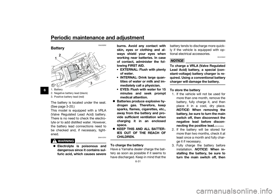
BatteryThe battery is located under the seat.
(See page 3-20.)
This model is equipped with a VRLA
(Valve Regulated Lead Acid) battery.
There is no need to check the electro-
lyte or to add distilled water. However,
the battery lead connections need to
be checked and, if necessary, tight-
ened.
WARNING
EWA10761
Electrolyte is poisonous an d
d an gerous since it contains sul-
furic aci d, which causes severe b
urns. Avoi d any contact with
skin, eyes or clothin g an d al-
ways shiel d your eyes when
workin g near b atteries. In case
of contact, a dminister the fol-
lowin g FIRST AID.
EXTERNAL: Flush with plenty of water.
INTERNAL: Drink lar ge quan-
tities of water or milk and im-
me diately call a physician.
EYES: Flush with water for 15 minutes an d seek prompt
me dical attention.
Batteries pro duce explosive hy-
d ro gen gas. Therefore, keep
sparks, flames, ci garettes, etc.,
away from the battery an d pro-
vi de sufficient ventilation when
char gin g it in an enclose d
space.
KEEP THIS AND ALL BATTER-
IES OUT OF THE REACH OF
CHILDREN.
To char ge the battery
Have a Yamaha dealer charge the bat-
tery as soon as possible if it seems to
have discharged. Keep in mind that the battery tends to discharge more quick-
ly if the vehicle is equipped with op-
tional electrical accessories.
NOTICE
ECA16522
To char
ge a VRLA (Valve Re gulate d
Lea d Aci d) battery, a special (con-
stant-volta ge) battery char ger is re-
quire d. Usin g a conventional b attery
char ger will damag e the b attery.To store the battery
1. If the vehicle will not be used for more than one month, remove the
battery, fully charge it, and then
place it in a cool, dry place.
NOTICE: When removin g the
b attery, be sure to turn the main
switch off, then disconnect the
ne gative lea d before discon-
nectin g the positive lea d.
[ECA16304]
2. If the battery will be stored for
more than two months, check it at
least once a month and fully char-
ge it if necessary.
3. Fully charge the battery before installation. NOTICE: When in-
stallin g the battery, be sure to
turn the main switch off, then
1. Battery
2. Negative battery lead (black)
3. Positive battery lead (red)
1
2
3
UBEHEAE0.book Page 31 Thursday, January 21, 2021 5:45 PM
Page 83 of 102
![YAMAHA TENERE 700 RALLY EDITION 2021 Owners Manual Periodic maintenance an d a djustment
6-32
6
connect the positive lea
d b efore
connectin g the ne gative lea d.
[ECA16842]
4. After installation, make sure that
the battery leads are properly con-
ne YAMAHA TENERE 700 RALLY EDITION 2021 Owners Manual Periodic maintenance an d a djustment
6-32
6
connect the positive lea
d b efore
connectin g the ne gative lea d.
[ECA16842]
4. After installation, make sure that
the battery leads are properly con-
ne](/manual-img/51/51790/w960_51790-82.png)
Periodic maintenance an d a djustment
6-32
6
connect the positive lea
d b efore
connectin g the ne gative lea d.
[ECA16842]
4. After installation, make sure that
the battery leads are properly con-
nected to the battery terminals.NOTICE
ECA16531
Always keep the b attery charged .
Storin g a dischar ged battery can
cause permanent battery damag e.
EAU47176
Replacin g the fusesThe main fuse and the fuse boxes,
which contain the fuses for the individ-
ual circuits, are located under the seat.
(See page 3-20.)TIPTo access the main fuse, remove the
starter relay cover as shown.
If a fuse is blown, replace it as follows.
1. Turn the key to “OFF” and turn off the electrical circuit in question.
2. Remove the blown fuse, and then install a new fuse of the specified
amperage. WARNING! Do not
1. Starter relay cover
2. Fuse box
3. Spare main fuse
4. Main fuse
2
3
4
1
1. ABS solenoid fuse
2. ABS motor fuse
3. Hazard fuse
4. Accessory fuse
5. Auxiliary fuse
6. ABS control unit fuse
7. Ignition fuse
8. Signaling system fuse
9. Headlight fuse
10.Fuel injection system fuse
11.Backup fuse (for clock and immobilizer sys-
tem)
12.Radiator fan motor fuse
13.Spare fuse
89
7
123456
101112
13
13
UBEHEAE0.book Page 32 Thursday, January 21, 2021 5:45 PM