2021 YAMAHA FX SVHO lock
[x] Cancel search: lockPage 49 of 116
Instrument operation
42
EJU45141Status area
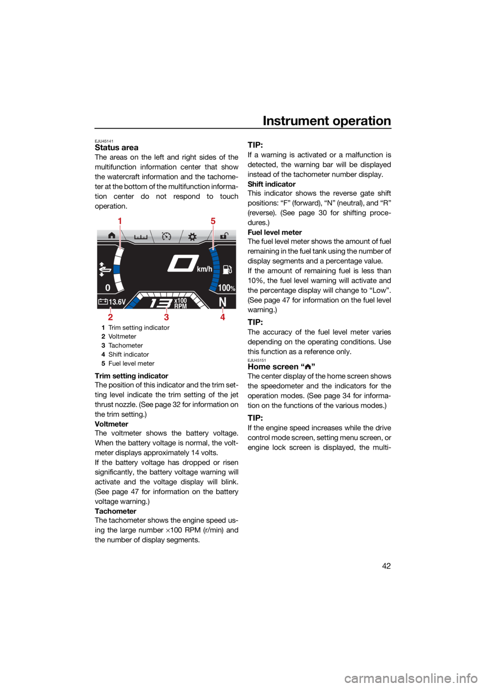
The areas on the left and right sides of the
multifunction information center that show
the watercraft information and the tachome-
ter at the bottom of the multifunction informa-
tion center do not respond to touch
operation.
Trim setting indicator
The position of this indicator and the trim set-
ting level indicate the trim setting of the jet
thrust nozzle. (See page 32 for information on
the trim setting.)
Voltmeter
The voltmeter shows the battery voltage.
When the battery voltage is normal, the volt-
meter displays approximately 14 volts.
If the battery voltage has dropped or risen
significantly, the battery voltage warning will
activate and the voltage display will blink.
(See page 47 for information on the battery
voltage warning.)
Tachometer
The tachometer shows the engine speed us-
ing the large number ×100 RPM (r/min) and
the number of display segments.
TIP:
If a warning is activated or a malfunction is
detected, the warning bar will be displayed
instead of the tachometer number display.
Shift indicator
This indicator shows the reverse gate shift
positions: “F” (forward), “N” (neutral), and “R”
(reverse). (See page 30 for shifting proce-
dures.)
Fuel level meter
The fuel level meter shows the amount of fuel
remaining in the fuel tank using the number of
display segments and a percentage value.
If the amount of remaining fuel is less than
10%, the fuel level warning will activate and
the percentage display will change to “Low”.
(See page 47 for information on the fuel level
warning.)
TIP:
The accuracy of the fuel level meter varies
depending on the operating conditions. Use
this function as a reference only.
EJU45151Home screen “ ”
The center display of the home screen shows
the speedometer and the indicators for the
operation modes. (See page 34 for informa-
tion on the functions of the various modes.)
TIP:
If the engine speed increases while the drive
control mode screen, setting menu screen, or
engine lock screen is displayed, the multi-
1 Trim setting indicator
2 Vo l t m et e r
3 Tachometer
4 Shift indicator
5 Fuel level meter
0
N13.6Vx100
RPM
100%
km/h
15
423
UF3X72E0.book Page 42 Friday, May 29, 2020 10:09 AM
Page 53 of 116

Instrument operation
46
Displaying the time since the last mainte-
nance (“Wellness”)
The total number of hours that the engine has
been running since the last watercraft main-
tenance can be displayed.
To reset the number of hours of operation:
(1) Tap the “Reset” button.
(2) Tap the “Confirm Reset” button to resetthe number of hours of operation.
Resetting the settings, trip information,
and fuel information (“Reset”)
The settings, trip information, and fuel infor-
mation can be reset to their factory default
settings. The items that are reset and the de-
fault settings are as follows.
Display units: US Unit
Language: English
Display brightness: 100%
Color setting: Blue
Trip time: 0.0
Distance traveled: 0.0
Average fuel consumption per gallon or li-
ter: 0.0
Total fuel used: 0.0
To reset the settings, trip information, and
fuel information:
(1) Tap the “Reset” button.
(2) Tap the “YES” button in the confirmation screen.
EJU45190Engine lock screen “ ”
The engine lock screen shows the setting
screen for the Yamaha Security System in the
center display. (See page 25 for Yamaha Se-
curity System setting procedures.)
EJU45202Warning function
The multifunction information center can indi-
cate the following warnings.
Fuel level warning
Battery voltage warning
Check engine warning
Engine overheat warning
Oil pressure warning
Other warnings (communication errors, ex-
ceeding the maintenance intervals, and so
on)
To stop the buzzer when a malfunction is ac-
tivated, correct the cause of the problem and
Reset
Time Since Last Maintenance
30.0Hr s
Reset
Reset To
Factory?
UF3X72E0.book Page 46 Friday, May 29, 2020 10:09 AM
Page 56 of 116
Equipment operation
49
EJU40335
EquipmentEJU45210Seats
The front and rear seats are removable.
Remove the seats to access the engine com-
partment and removable watertight storage
compartment.
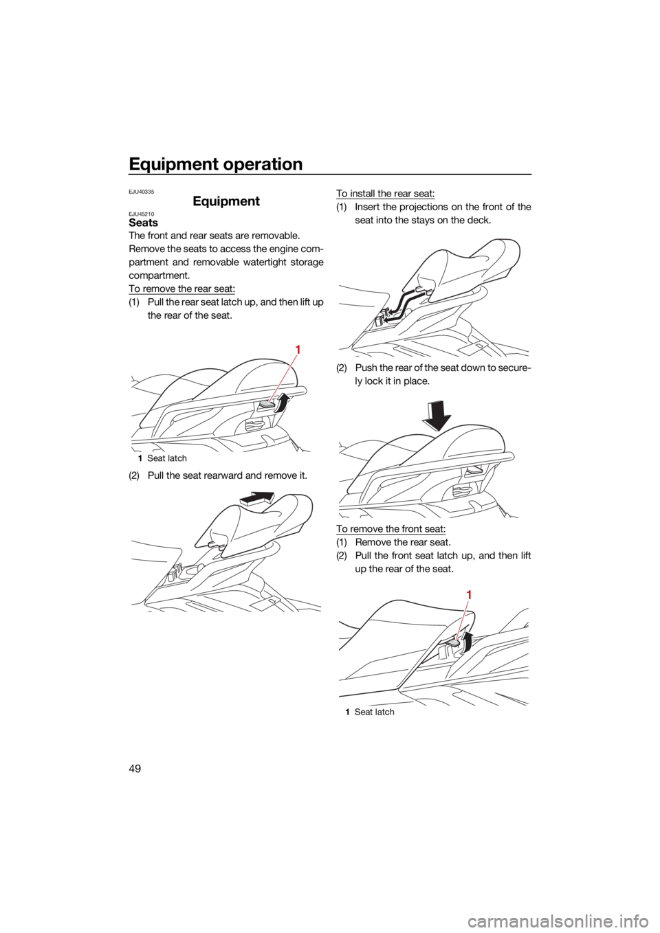
To remove the rear seat:
(1) Pull the rear seat latch up, and then lift upthe rear of the seat.
(2) Pull the seat rearward and remove it. To install the rear seat:
(1) Insert the projections on the front of the
seat into the stays on the deck.
(2) Push the rear of the seat down to secure- ly lock it in place.
To remove the front seat:
(1) Remove the rear seat.
(2) Pull the front seat latch up, and then lift up the rear of the seat.
1Seat latch
1
1Seat latch
1
UF3X72E0.book Page 49 Friday, May 29, 2020 10:09 AM
Page 57 of 116
Equipment operation
50
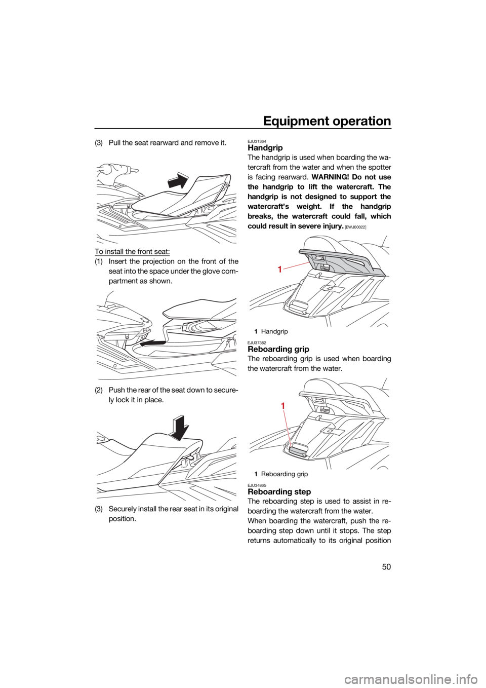
(3) Pull the seat rearward and remove it.
To install the front seat:
(1) Insert the projection on the front of theseat into the space under the glove com-
partment as shown.
(2) Push the rear of the seat down to secure- ly lock it in place.
(3) Securely install the rear seat in its original position.
EJU31364Handgrip
The handgrip is used when boarding the wa-
tercraft from the water and when the spotter
is facing rearward. WARNING! Do not use
the handgrip to lift the watercraft. The
handgrip is not designed to support the
watercraft’s weight. If the handgrip
breaks, the watercraft could fall, which
could result in severe injury.
[EWJ00022]
EJU37382
Reboarding grip
The reboarding grip is used when boarding
the watercraft from the water.
EJU34865Reboarding step
The reboarding step is used to assist in re-
boarding the watercraft from the water.
When boarding the watercraft, push the re-
boarding step down until it stops. The step
returns automatically to its original position
1Handgrip
1 Reboarding grip
1
1
UF3X72E0.book Page 50 Friday, May 29, 2020 10:09 AM
Page 60 of 116
Equipment operation
53
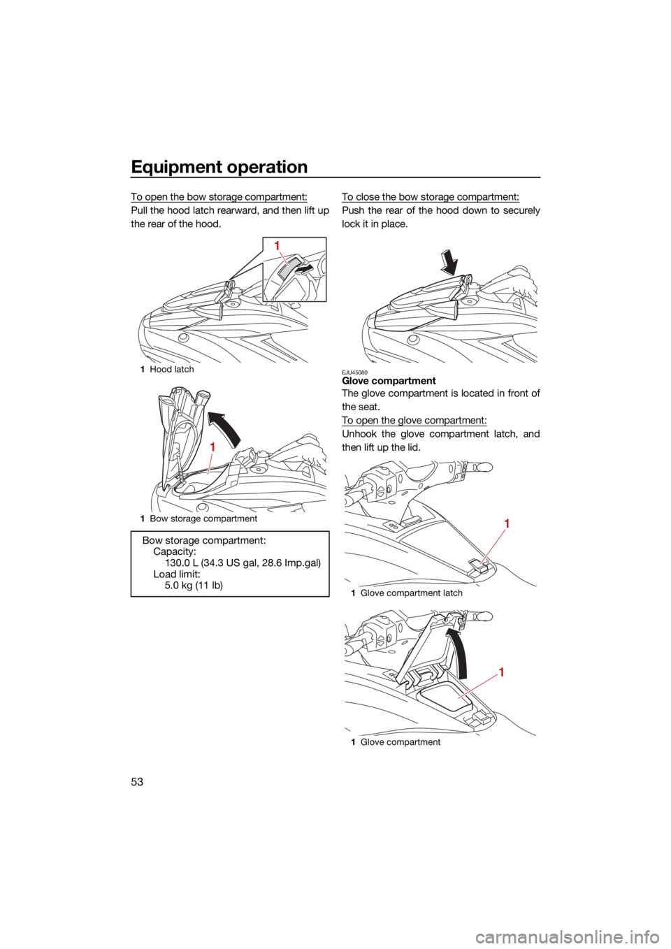
To open the bow storage compartment:
Pull the hood latch rearward, and then lift up
the rear of the hood.To close the bow storage compartment:Push the rear of the hood down to securely
lock it in place.
EJU45080Glove compartment
The glove compartment is located in front of
the seat.
To open the glove compartment:
Unhook the glove compartment latch, and
then lift up the lid.
1
Hood latch
1 Bow storage compartment
Bow storage compartment:
Capacity:130.0 L (34.3 US gal, 28.6 Imp.gal)
Load limit: 5.0 kg (11 lb)
1
1
1Glove compartment latch
1 Glove compartment
1
1
UF3X72E0.book Page 53 Friday, May 29, 2020 10:09 AM
Page 63 of 116
Equipment operation
56
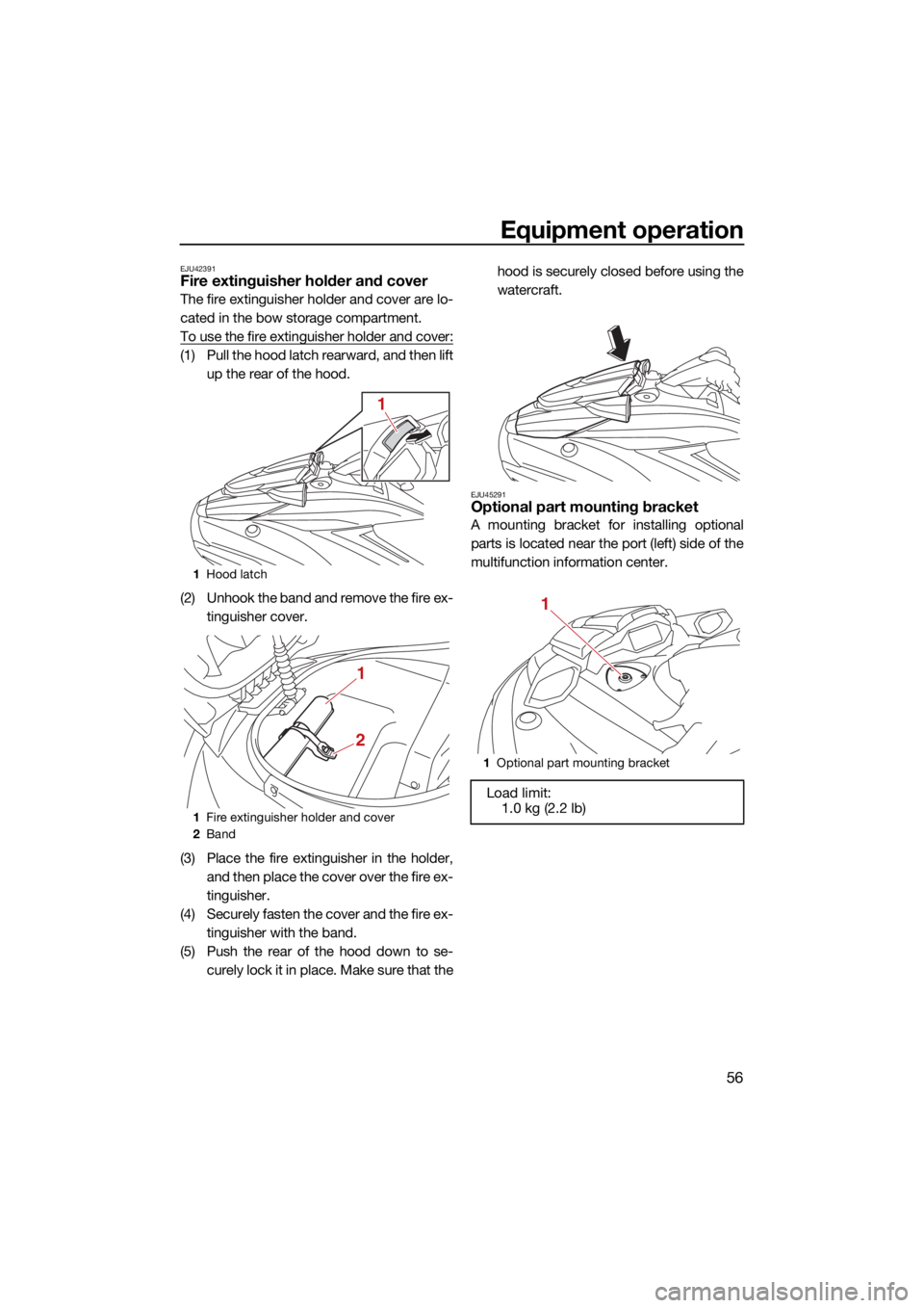
EJU42391Fire extinguisher holder and cover
The fire extinguisher holder and cover are lo-
cated in the bow storage compartment.
To use the fire extinguisher holder and cover:
(1) Pull the hood latch rearward, and then liftup the rear of the hood.
(2) Unhook the band and remove the fire ex- tinguisher cover.
(3) Place the fire extinguisher in the holder, and then place the cover over the fire ex-
tinguisher.
(4) Securely fasten the cover and the fire ex- tinguisher with the band.
(5) Push the rear of the hood down to se- curely lock it in place. Make sure that the hood is securely closed before using the
watercraft.
EJU45291Optional part mounting bracket
A mounting bracket for installing optional
parts is located near the port (left) side of the
multifunction information center.
1
Hood latch
1 Fire extinguisher holder and cover
2 Band
1
1
2
1Optional part mounting bracket
Load limit:
1.0 kg (2.2 lb)
1
UF3X72E0.book Page 56 Friday, May 29, 2020 10:09 AM
Page 71 of 116

Pre-operation checks
64
EJU31982
EWJ00412
Failure to inspect or maintain the watercraft properly increases the possibility of an ac-
cident or damage to the watercraft. Do not operate the watercraft if you find any prob-
lem. If a problem cannot be corrected by the procedures provided in this manual, have
the watercraft inspected by a Yamaha dealer.
EJU41235Pre-operation checklist
Before using this watercraft, be sure to perform the checks in the following checklist.
ITEMROUTINEPAGE
PRE-LAUNCH CHECKS
Engine compartment Ventilate the engine compartment.
Check inside the engine compartment for damage.
66
Fuel system Check the fuel system for leakage.
Check the fuel level in the fuel tank.
66
Water separator Check the water separator for water. 67
Engine unit Check the exterior of the engine unit for damage. 67
Engine oil level Check the engine oil level. 67
Bilge water Check the engine compartment for bilge water. 67
Battery Check the battery connections. 67
Steering system Check the steering system for proper operation. 68
Adjustable tilt steering sys-
tem Check the adjustable tilt steering system for proper
operation and check that the handlebars are se-
curely locked in place.
69
RiDE lever Check the RiDE lever for proper operation. 69
Throttle lever Check the throttle lever for proper operation. 69
Yamaha Security System Check the Yamaha Security System for proper op-
eration.
69
Engine shut-off cord (lan-
yard) Check the engine shut-off cord (lanyard) for dam-
age.
69
Switches Check the start switch, engine stop switch, and en-
gine shut-off switch for proper operation.
69
Electric trim system Check the electric trim system for proper operation. 70
Storage compartments Check the storage compartments for damage and
water.
70
Fire extinguisher holder,
cover, and band Check the fire extinguisher holder, cover, and band
for damage.
70
Fire extinguisher Check the condition of the fire extinguisher. 71
Safety equipment Check that safety equipment meeting the applica-
ble regulations is on board.
71
Hull and deck Check the hull and deck for damage. 71
Jet intake Check the jet intake for damage and clogging. 71
UF3X72E0.book Page 64 Friday, May 29, 2020 10:09 AM
Page 76 of 116
Pre-operation checks
69
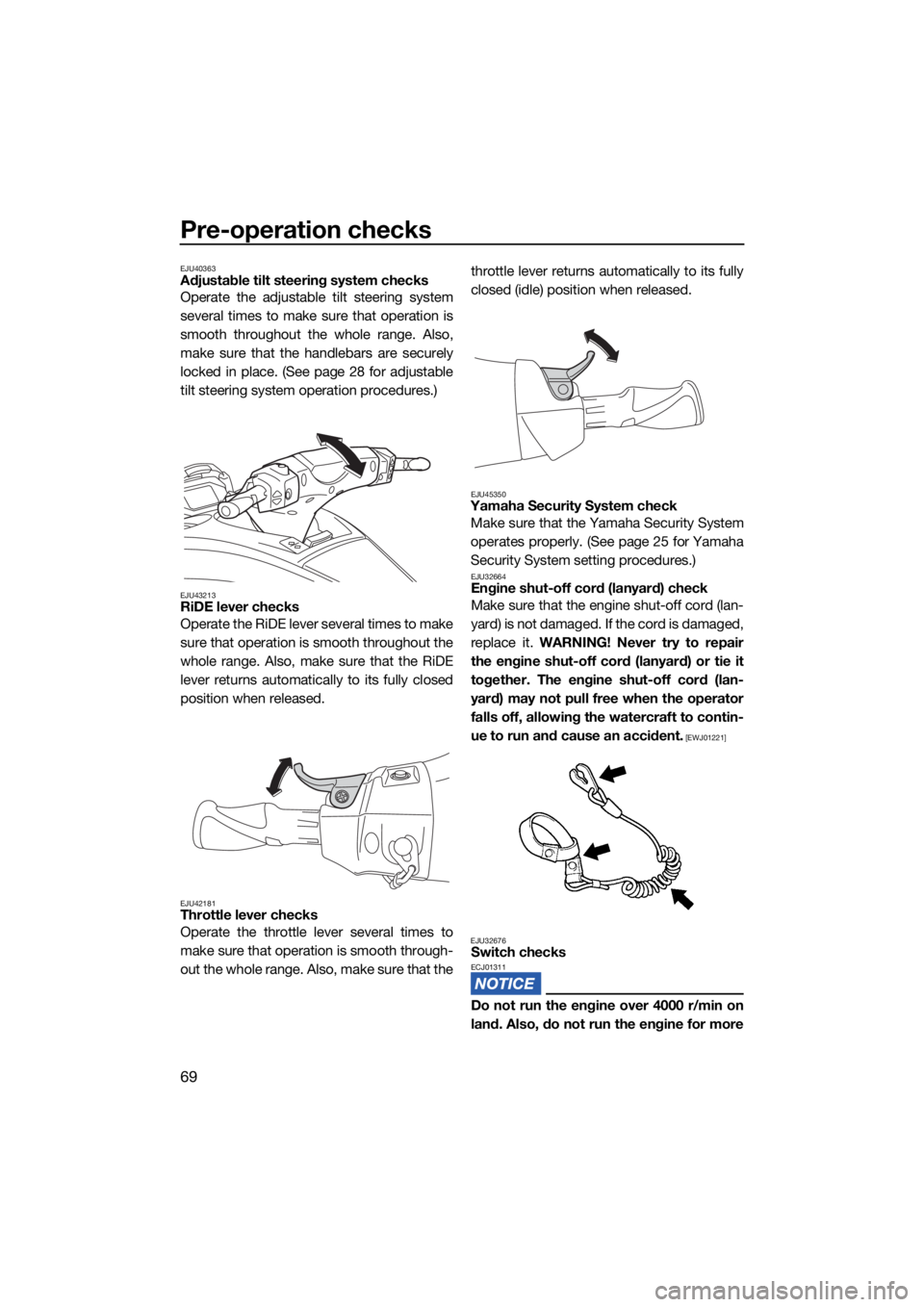
EJU40363Adjustable tilt steering system checks
Operate the adjustable tilt steering system
several times to make sure that operation is
smooth throughout the whole range. Also,
make sure that the handlebars are securely
locked in place. (See page 28 for adjustable
tilt steering system operation procedures.)
EJU43213RiDE lever checks
Operate the RiDE lever several times to make
sure that operation is smooth throughout the
whole range. Also, make sure that the RiDE
lever returns automatically to its fully closed
position when released.
EJU42181Throttle lever checks
Operate the throttle lever several times to
make sure that operation is smooth through-
out the whole range. Also, make sure that thethrottle lever returns automatically to its fully
closed (idle) position when released.
EJU45350Yamaha Security System check
Make sure that the Yamaha Security System
operates properly. (See page 25 for Yamaha
Security System setting procedures.)
EJU32664Engine shut-off cord (lanyard) check
Make sure that the engine shut-off cord (lan-
yard) is not damaged. If the cord is damaged,
replace it. WARNING! Never try to repair
the engine shut-off cord (lanyard) or tie it
together. The engine shut-off cord (lan-
yard) may not pull free when the operator
falls off, allowing the watercraft to contin-
ue to run and cause an accident.
[EWJ01221]
EJU32676
Switch checksECJ01311
Do not run the engine over 4000 r/min on
land. Also, do not run the engine for more
UF3X72E0.book Page 69 Friday, May 29, 2020 10:09 AM