2021 VOLKSWAGEN T-ROC clock
[x] Cancel search: clockPage 312 of 502

Release pin with coloured marking
The removable ball head is located with the vehicle toolkit in the luggage compartment.
Step 1: preparations
Remove the cap from the ball head mounting under the rear bumper ⇒ Rear view and stow in the
vehicle.
Starting from the bottom right side, swivel the trailer socket as far as possible to the top left. This
gives you access to the ball head mounting.
Check to ensure that the mounting, locking lever ⇒ Fig. 155 ⑥, shank ④ and the retaining balls
③ of the ball head are all clean and not damaged ⇒ . Clean if necessary.
Step 2: check whether the ball head is pre-tensioned
The ball head cannot be fitted properly unless it is pre-tensioned.
The following conditions must be fulfilled:
The lock cover ⇒ Fig. 155 ⑧ is open and the key ⑦ is inserted
The release pin ⑨ can be moved.
The locking lever ⑥ is in the bottom position.
All retaining balls ③ can be pressed fully into the shank ④.
If all these conditions are met, continue with Step 4.
If conditions are not met, continue with Step 3.
Step 3: pre-tensioning the ball head
If the ball head is not pre-tensioned, pre-tension the ball head as follows:
Remove the lock cover ⑧ from the lock and insert the key ⑦ into the lock.
Turn the key ⑦ anti-clockwise until the part of the key with the hole is at the top.
Press the release pin ⑨ and at the same time press the locking lever ⑥ down as far as it will go ⇒
. The locking lever remains locked in this position.
Step 4: attaching the pre-tensioned ball head to the vehicle
Do not touch the locking lever once the ball head has been pre-tensioned. When the ball head is
engaged, the locking lever will spring back to its original position and could cause injury ⇒ .
Guide the pre-tensioned removable ball head into the mounting tube from below.
Push the ball head firmly upwards until it engages. The centring devices ⇒ Fig. 155 ⑤ must engage
in the mounting points on the vehicle.
The locking lever ⑥ automatically turns up to its original position and the green section of the
release pin ⑨ is visible.
Page 313 of 502

Turn the key ⑦ clockwise until the part of the lock with the holes is at the top.
Fit the lock cap ⑧ on the lock and place the key ⑦ in the vehicle toolkit.
Step 5: safety check
Before hitching a trailer, check if the ball head is fixed correctly.
The locking lever ⇒ Fig. 155 ⑥ is in the uppermost position.
The green section of the release pin ⑨ is visible.
Shake the ball head ② or pull it down with some force. It must sit firmly in the mounting ⇒ .
The lock must be locked and the key ⑦ removed.
The lock cover ⑧ must cover the lock in the locking lever.
WARNING
Improper use of the towing bracket can cause injuries and accidents.
t diameter of the ball ⇒ Fig. 155 ③ is less than 49 mm, do not use the towing
bracket.
injuries.
been pre-tensioned. When the ball head is
pressed into the mounting, the locking lever will spring back to its original position.
workshop.
wing bracket if the ball head does not engage properly or if you are unable to
pre-tension it.
ball head has been mounted. This means that ball head is not locked properly.
NOTICE
and undamaged. Otherwise you may not be able to lock the ball head securely.
-pressure hose or steam cleaner directly at the ball head mounting. This could
wash the grease required for lubrication out of the mounting.
1) Not always included in the scope of delivery.
Page 314 of 502

Removing the ball head
First read and observe the introductoryinformation and safety warnings⇒Introduction
⇒ Electronic parking brake .
ailer and disconnect the electrical connection between the vehicle and the trailer.
If fitted, remove adapters from the trailer socket.
⇒ Fig. 155 ⑧ from the lock in the locking lever and insert the key ⑦ into
the lock.
e key ⑦ anti-clockwise until the part of the key with the hole is at the top.
② with your hand.
⑨ and at the same time press the locking lever ⑥ down as far as it will go
⇒ . The ball head is pre-tensioned.
⑥ and stow the pre-tensioned ball head safely with the vehicle toolkit.
② with your hand.
damage to the mounting.
WARNING
The removable ball head is heavy. The ball head could fall while it is being removed. This could cause
injuries.
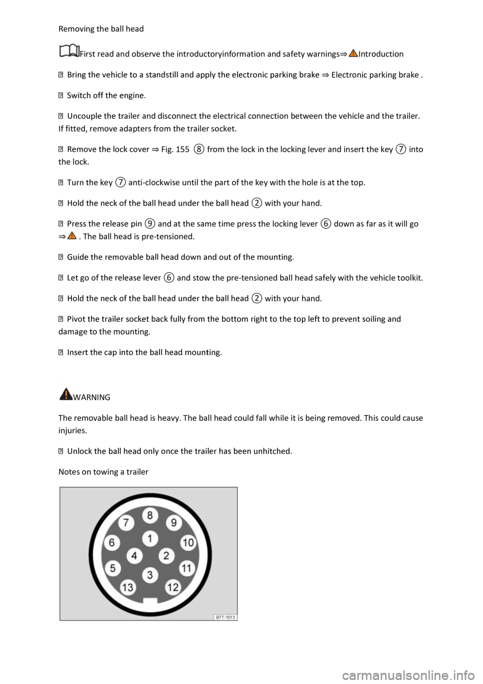
Notes on towing a trailer
Page 342 of 502

Fig. 167 In the engine compartment: changing bulbs in the left front headlight.
First read and observe the introductoryinformation and safety warnings⇒Introduction
The front headlight does not need to be removed when changing bulbs.
The actions should always be carried out in the specified order:
⇒ Fig. 166 and ⇒ Fig. 167
Observe and follow the instructions on the checklist ⇒ Checklist Information on changing
bulbs
Open the bonnet ⇒ In the engine compartment .
Pull off the rubber cover on the rear side of the headlight. Depending on the version, a hard plastic
cover may be fitted here. Turn the cover anti-clockwise and remove it.
Dipped beam ① Turn the bulb holder anticlockwise as far as it will go and carefully pull it out to the
rear along with the bulb.
Main beam ② Press on the bulb from below, as shown by the arrow, until it engages. Lift the bulb
back and out.
Replace the defective bulb with a new bulb of the same type.
Dipped beam ① Insert the bulb holder into the headlight and turn it clockwise as far as it will go.
Main beam ② Insert the bulb into the opening in the headlight with the connector at the top and
push down. The lug of the bulb must be located in the headlight recess (small arrow).
Page 343 of 502

Attach the rubber cover or hard plastic cover and turn it clockwise as far as it will go.
Close the bonnet ⇒ In the engine compartment .
Changing the bulbs in the headlights (lights with LED technology)
First read and observe the introductoryinformation and safety warnings⇒Introduction
These lamps use LED technology. The LEDs cannot be replaced by customers. If some LEDs fail, this
may be an indication that more elements are on the point of failure. In this case, have the lights
checked and renewed if necessary at a qualified workshop.
Changing the front turn signal bulbs
Fig. 168 In the front right wheel housing liner: changing a turn signal bulb.
First read and observe the introductoryinformation and safety warnings⇒Introduction
The actions should only be carried out in the specified order:
Observe and follow the instructions in the checklist ⇒ Checklist Information on changing
bulbs .
Turn the steering so that the wheel on the affected side of the vehicle is pointing to the
middle of the vehicle. If necessary, start the engine to do this. Then stop the engine again and
remove the vehicle key from the ignition lock.
Turn the cover in the wheel housing liner in the direction of the arrow and remove it
⇒ Fig. 168 .
Release the connector ⇒ Fig. 168 ① and detach it.
Turn the bulb holder ⇒ Fig. 168 ② anti-clockwise (arrow) as far as it will go and pull it out to
the rear along with the bulb.
Replace the defective bulb with a new bulb of the same type.
Insert the bulb holder into the headlight and turn it clockwise as far as it will go.
Page 344 of 502

Fit the connector ⇒ Fig. 168 ① on the bulb holder ⇒ Fig. 168 ②. The connector should
click into place.
Fit the cover in the wheel housing liner ⇒ Fig. 168 and lock it in position.
NOTICE
the headlight housing is seated properly in order to
prevent damage to the electrical system caused by water entering the system.
damaged.
Changing bulbs in the front bumper
Fig. 169 In the front bumper, right-hand side: removing the fog light.
First read and observe the introductoryinformation and safety warnings⇒Introduction
The actions should only be carried out in the specified order:
Observe and follow the instructions in the checklist ⇒ Checklist Information on changing
bulbs .
Take the wire hook from the toolkit and insert it in the opening in the cover ⇒ Fig. 169 . Pull
the cover forwards in the direction of the arrow.
Use the screwdriver from the vehicle toolkit to unscrew the securing screws ⇒ Fig. 169 ①
⇒ Vehicle toolkit .
Pull the headlight out of the bumper towards the outside of the vehicle.
Release the connector and pull it off.
Turn the bulb holder anti-clockwise as far as it will go and pull it out to the rear along with the
bulb.
Page 345 of 502

Replace the defective bulb with a new bulb of the same type.
Insert the bulb holder into the headlight and turn it clockwise as far as it will go.
Connect the connector to the bulb holder. The connector must audibly click into place.
Push the headlight from the outside into the openings and insert into the bumper.
Use the screwdriver to tighten the securing screws ⇒ Fig. 169 ①.
Fit the cover in the bumper ⇒ Fig. 169 .
Stow the wire hook and screwdriver in the vehicle toolkit.
Changing bulbs in the tail light clusters (LED lights)
First read and observe the introductoryinformation and safety warnings⇒Introduction
These lamps use LED technology. The LEDs cannot be replaced by customers. If some LEDs fail, this
may be an indication that more elements are on the point of failure. In this case, have the lights
checked and renewed if necessary at a qualified workshop. Volkswagen recommends using a
Volkswagen dealership for this purpose.
Changing bulbs in the number plate light (LED lights)
First read and observe the introductoryinformation and safety warnings⇒Introduction
These lamps use LED technology. The LEDs cannot be replaced by customers. If some LEDs fail, this
may be an indication that more elements are on the point of failure. In this case, have the lights
checked and renewed if necessary at a qualified workshop.
Troubleshooting
First read and observe the introductoryinformation and safety warnings⇒Introduction
Fault in vehicle lighting
The indicator lamp lights up yellow.
Fault in vehicle lighting or fault in cornering lights.
Check the vehicle lighting and change the appropriate bulb as required ⇒ Changing bulbs . If all
bulbs are OK or there is a fault in the dynamic cornering light, go to a qualified workshop.
Changing fuses
Introduction
This chapter contains information on the followingsubjects:
⇒ Fuses in the dash panel
Page 360 of 502

Comply with the notes on towing ⇒ Notes on tow-starting and towing .
Fitting the rear towing eye
⇒ Vehicle toolkit .
area of the cover ⇒ Fig. 178 in the direction of the arrow to release the cover.
⇒ Fig. 179 and tighten as far as it will go ⇒ .
Use a suitable object to screw the towing eye fully and securely into the mounting.
clockwise.
-clockwise.
compartment.
NOTICE
urely into the mounting. Otherwise, the
towing eye can be torn out of the mounting when the vehicle is being tow-started or towed.
-fitted towing bracket must be towed only using tow bars that are specially
designed for fitting to a ball coupling. If you use an unsuitable tow bar, the ball coupling and the
vehicle could be damaged. You should use a tow rope instead.
Fitting the front towing eye
Fig. 180 In the front bumper on the right: removing the cover.