2021 TOYOTA RAV4 PHEV belt
[x] Cancel search: beltPage 61 of 666
59
1
1-2. Child safety
For safety and security
The child restraint systems mentioned in the table may not be a vailable out-
side the EU area.
When securing some types of child
restraint systems in rear seat, it
may not be possible to properly use
the seat belts in positions next to
the child restraint without interfering
with it or affecti ng seat belt effec-
tiveness. Be sure you r seat belt fits
snugly across your shoulder and
low on your hips. If it does not, or if
it interferes with the child restraint,
move to a different position. Failure
to do so may result in death or seri -
ous injury.
When installing a child restraint
in the rear seats, adjust the front
seat so that it does not interfere
with the child or child restraint
system.
When installing a child seat with
support base, if the child seat
interferes with the seatback
when latching it into the support
base, adjust the seatback rear -
ward until there is no interfer -
ence.
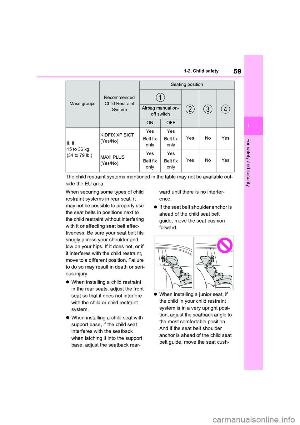
If the seat belt shoulder anchor is
ahead of the child seat belt
guide, move the seat cushion
forward.
When installing a junior seat, if
the child in your child restraint
system is in a very upright posi -
tion, adjust the seatback angle to
the most comfortable position.
And if the seat belt shoulder
anchor is ahead of the child seat
belt guide, move the seat cush -
II, III
15 to 36 kg
(34 to 79 lb.)
KIDFIX XP SICT
(Yes/No)
Yes
Belt fix
only
Yes
Belt fix
only
YesNoYes
MAXI PLUS
(Yes/No)
Yes
Belt fix
only
Yes
Belt fix
only
YesNoYes
Mass groups
Recommended
Child Restraint
System
Seating position
Airbag manual on-
off switch
ONOFF
Page 62 of 666

601-2. Child safety
ion forward.
Confirm with the operation manua l enclosed with the child restraint system
about the installation of th e child restraint system.
Child restraint system installation method
Installation methodPage
Seat belt attachmentP.61
ISOFIX lower anchorage
attachmentP.62
Top tether anchorage
attachmentP.63
Page 63 of 666
61
1
1-2. Child safety
For safety and security
■Installing child restraint sys -
tem using a seat belt
Install the child restraint system in
accordance to the operation man -
ual enclosed with the child restraint
system.
If the child restraint system on hand
is not within the “universal” cate -
gory (or the necessary information
is not in the tabl e), refer to the
“Vehicle List” provided by the child
restraint system maker for various
possible installation positions, or
check the compatibility after asking
the retailer of the child seat.
( →P.55, 56)
1 If installing the child restraint
system to the front passenger
seat is unavoidable, refer to
P.52 for the front passenger
seat adjustment.
2 Adjust the seatback angle to the
most upright position. When
installing a forward-facing child
seat, if there is a gap between
the child seat a nd the seatback,
adjust the seatback angle until
good contact is achieved.
3 If the head restraint interferes
with the child restraint system
installation and the head
restraint can be removed,
remove the head restraint. Oth-
erwise, put the head restraint in
the upper most position.
( →P.276)
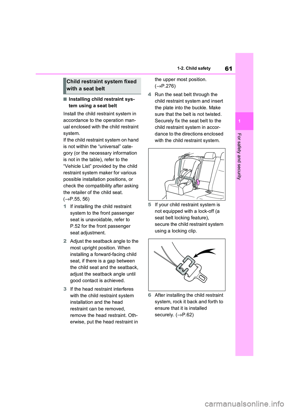
4 Run the seat belt through the
child restraint system and insert
the plate into the buckle. Make
sure that the belt is not twisted.
Securely fix the s eat belt to the
child restraint system in accor -
dance to the directions enclosed
with the child restraint system.
5 If your child restraint system is
not equipped with a lock-off (a
seat belt locking feature),
secure the child restraint system
using a locking clip.
6 After installing the child restraint
system, rock it back and forth to
ensure that it is installed
securely. ( →P.62)
Child restraint system fixed
with a seat belt
Page 64 of 666

621-2. Child safety
■Removing a child restraint
system installed with a seat
belt
Press the buckle release button
and fully retract the seat belt.
When releasing the buckle, the child
restraint system may spring up due to
the rebound of the seat cushion.
Release the buckle while holding down
the child restraint system.
Since the seat belt automatically reels
itself, slowly return it to the stowing
position.
■When installing a child restraint
system
You may need a locking clip to install the child restraint s ystem. Follow the
instructions provided by the manufac -
turer of the system. If your child restraint system does not provide a locking clip,
you can purchase the following item
from any authorized Toyota retailer or Toyota authorized repairer, or any reli -
able repairer: Locking clip for child
restraint system (Part No. 73119-22010)
■ISOFIX lower anchorages
(ISOFIX child restraint system)
Lower anchorages are provided for
the outboard rear seats. (Tags dis -
playing the location of the anchor -
ages are attached to the seats.)
WARNING
■When installing a child restraint
system
Observe the following precautions. Failure to do so may result in death or
serious injury.
●Do not allow children to play with
the seat belt. I f the seat belt
becomes twisted around a child’s neck, it may lead to choking or
other serious injuries that could
result in death. If this occurs and the buckle cannot be unfastened,
scissors should be used to cut the
belt.
●Ensure that the bel t and plate are securely locked and the seat belt is
not twisted.
●Shake the child restraint system left
and right, and forward and back -
ward to ensure that it has been securely installed.
●After securing a ch ild restraint sys- tem, never adjust the seat.
●When a junior seat is installed, always ensure that the shoulder
belt is positioned a cross the center
of the child’s shoulder. The belt should be kept away from the
child’s neck, but not so that it could
fall off the chil d’s shoulder.
●Follow all installation instructions
provided by the child restraint sys - tem manufacturer.
Child restraint system fixed
with an ISOFIX lower
anchorage
Page 65 of 666

63
1
1-2. Child safety
For safety and security
■Installation with ISOFIX lower
anchorage (ISOFIX child
restraint system)
Install the child restraint system in
accordance to the operation man -
ual enclosed with the child restraint
system.
If the child restraint system on hand
is not within the “universal” cate -
gory (or the necessary information
is not in the tabl e), refer to the
“Vehicle List” provided by the child
restraint system maker for various
possible installation positions, or
check the compatibility after asking
the retailer of the child seat.
( →P.55, 56)
1 Adjust the seatback angle to the
most upright position. When
installing a forward-facing child
seat, if there is a gap between
the child seat a nd the seatback,
adjust the seatback angle until
good contact is achieved.
2 If the head restraint interferes
with the child restraint system
installation and the head
restraint can be removed,
remove the head restraint. Oth-
erwise, put the head restraint in
the upper most position.
( →P.276)
3 Check the positions of the exclu-
sive fixing bars, and install the
child restraint system to the
seat.
The bars are installed in the clearance
between the seat cushion and seat -
back.
4 After installing the child restraint
system, rock it back and forth to
ensure that it is installed
securely. ( →P.62)
■Top tether anchorages
Top tether anchorages are pro -
WARNING
■When installing a child restraint
system
Observe the following precautions. Failure to do so may result in death or
serious injury.
●After securing a ch ild restraint sys-
tem, never adjust the seat.
●When using the lower anchorages,
be sure that there are no foreign
objects around the anchorages and that the seat belt is not caught
behind the child restraint system.
●Follow all installation instructions
provided by the child restraint sys -
tem manufacturer.
Using a top tether anchor -
age
Page 66 of 666

641-2. Child safety
vided for the outboard rear seats.
Use top tether anchorages when
fixing the top strap.
Top tether anchorages
Top strap
■Fixing the top strap to the top
tether anchorages
Install the child restraint system in
accordance to the operation man -
ual enclosed with the child restraint
system.
1 Adjust the head restraint to the
upmost position.
If the head restraint interferes with the
child restraint system or top strap installation and the head restraint can
be removed, remove the head restraint.
( →P.276)
2Latch the hook onto the top
tether anchorage and tighten
the top strap.
Make sure the top strap is securely
latched. ( →P.62) When installing the child restraint sys-
tem with the head restraint being
raised, be sure to have the top strap pass underneath the head restraint.
Hook
Top strap
A
B
WARNING
■When installing a child restraint
system
Observe the following precautions. Failure to do so may result in death or
serious injury.
●Firmly attach the top strap and
make sure that the belt is not
twisted.
●Do not attach the top strap to any-
thing other than the top tether anchorages.
●After securing a ch ild restraint sys- tem, never adjust the seat.
●Follow all installation instructions provided by the child restraint sys -
tem manufacturer.
●When installing the child restraint
system with the head restraint
being raised, after the head restraint has been raised and then
the top tether anchorage has been
fixed, do not lower the head restraint.
A
B
Page 69 of 666

67
1
1-3. Emergency assistance
For safety and security
at the following URL.
http://www.opensourceautomotive.com/dcm/toyota/
WARNING
■When the Emergency Call may
not be made
●It may not be possible to make
Emergency Calls in any of the fol-
lowing situations. In such cases,
report to emergen cy services pro- vider (112 system etc.) by other
means such as nearby public
phones.
• Even when the vehicle is in the cel -
lular phone service area, it may be
difficult to connec t to the eCall con- trol center if the reception is poor or
the line is busy. In such cases,
even though the system attempts to connect to the eCall control center,
you may not be able to connect to
the eCall control center to make Emergency Calls and contact emer -
gency services.
• When the vehicle is out of the cellu -
lar phone service area, the Emer -
gency Calls cannot be made.
• When any related equipment (such
as the “SOS” button panel, indicator lights, microphone, speaker, DCM,
antenna, or any wires connecting
the equipment) is malfunctioning, damaged or broken, the Emer -
gency Call cannot be made.
• During an Emergency Call, the sys -
tem makes repeated attempts to
connect to the eCall control center. However, if it cannot connect to the
eCall control center due to poor
radio wave reception, the system may not be able to connect to the
cellular network and the call may
finish without connecting. The red indicator light will blink for approxi -
mately 30 seconds to indicate this
disconnection.
●If the 12-volt battery’s voltage decreases or there is a disconnec -
tion, the system may not be able to
connect to the eCa ll control center.
■When the Emergency Call sys-
tem is replaced with a new one
The Emergency Call system should
be registered. Contact any authorized
Toyota retailer or Toyota authorized repairer, or any reliable repairer.
■For your safety
●Please drive safely.
The function of t his system is to
assist you in making the Emer - gency Call in case of accidents
such as traffic a ccidents or sudden
medical emergenc ies, and it does not protect the driver or passengers
in any way. Please drive safely and
fasten your seatbelts at all times for your safety.
●In case of an emergency, make lives the top priority.
●If you smell anything burning or other unusual smells, leave the
vehicle and evacuate to a safe area
immediately.
●If the airbags dep loy when the sys-
tem is operating normally, the sys- tem makes emerge ncy call. The
system also makes emergency call
when the vehicle is struck from the rear or rolls over , even if the air-
bags do not deploy.
●For safety, do not make the Emer -
gency Call while driving.
Making calls during driving may cause mishandling of the steering
wheel, which may lead to unex -
pected accidents.
Stop the vehicle and confirm the safety of your su rroundings before
making the Emergency Call.
Page 172 of 666

1703-1. Instrument cluster
Warning lights inform the driver of
malfunctions in the indicated vehi -
cle’s systems.
*1: These lights turn on when the power
switch is turned to ON to indicate
that a system check is being per -
formed. They will turn off after the
hybrid system is on , or after a few
seconds. There may be a malfunc-
tion in a system if the light does not
come on, or turn off. Have the vehi -
cle inspected by any authorized
Toyota retailer or Toyota authorized
repairer, or any reliable repairer.
Warning lights
(Red)
Brake system warning
light*1 ( →P.568)
(Yellow)
Brake system warning
light*1 ( →P.568)
Charging system warn -
ing light*1 ( →P.569)
High coolant temperature
warning light*2 ( →P.569)
Hybrid system overheat
warning light*2 ( →P.569)
Low engine oil pressure
warning light*2 ( →P.569)
Malfunction indicator
lamp*1 ( →P.570)
SRS warning light*1
( →P.570)
ABS warning light*1
( →P.570)
(Red/yellow)
Electric power steering
system warning light*1
( →P.570)
(Flashes or illu- minates)
PCS warning light*1 (if
equipped) ( →P.571)
(Orange)
LTA indicator (if
equipped) ( →P.571)
Toyota parking assist-
sensor OFF indicator*3 ( i f
equipped) ( →P.572)
PKSB OFF indicator*1 (if
equipped) ( →P.572)
BSM OFF indicator*1 (if
equipped) ( →P.573)
RCTA OFF indicator*1 (if
equipped)
( →P.573)
Slip indicator light*1
( →P.573)
Brake Override Sys -
tem/Drive-Start Con -
trol/PKSB (if equipped)
warning light*2 ( →P.574)
(Flashes)
Brake hold operated indi-
cator*1 ( →P.574)
(Flashes)
Parking brake indicator
( →P.574)
Tire pressure warning
light*1 ( →P.575)
Low fuel level warning
light ( →P.575)
Driver’s and front pas -
senger’s seat belt
reminder light ( →P.575)
Rear passengers’ seat
belt reminder lights
( →P.576)