2021 TOYOTA PROACE CITY tailgate
[x] Cancel search: tailgatePage 98 of 272
98
(b) Group 0: from birth to 10 kg (22 lb). Carrycots and "car" infant carriers must not be installed on the f\
ront passenger seat(s).(c) Universal child seat: child seat suitable for installation in all vehic\
les using the seat belt.U Seat position suitable for installing a child seat secured using the se\
at belt and universally approved for rearward-facing and/or forward-faci\
ng use.UF Seat position suitable for installing a child seat secured using a seat\
belt and universally approved for forward-facing use.X Seat position not suitable for installing a child seat for the stated w\
eight class.
Manual child lock
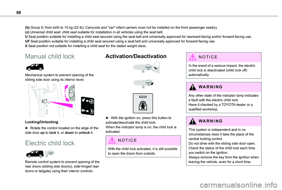
Mechanical system to prevent opening of the sliding side door using its interior lever.
Locking/Unlocking
► Rotate the control located on the edge of the side door up to lock it, or down to unlock it.
Electric child lock
Remote control system to prevent opening of the rear doors (sliding side door(s), side-hinged rear doors or tailgate) using their interior controls.
Activation/Deactivation
► With the ignition on, press this button to activate/deactivate the child lock.When the indicator lamp is on, the child lock is
activated.
NOTIC E
With the child lock activated, it is still possible to open the doors from outside.
NOTIC E
In the event of a serious impact, the electric child lock is deactivated (child lock off) automatically.
WARNI NG
Any other state of the indicator lamp indicates a fault with the electric child lock.Have it checked by a TOYOTA dealer or a qualified workshop.
WARNI NG
This system is independent and in no circumstances does it take the place of the central locking control.Do not drive with the sliding side door open.Check the status of the child lock each time you switch on the ignition.Always remove the key from the ignition when leaving the vehicle, even for a short time.
Page 146 of 272
146
WARNI NG
Obstacles may appear further away than they actually are.During parking manoeuvres and lane changes, it is important to check the sides of the vehicle using the mirrors.The rear parking sensors also supplement the information on the vehicle's surroundings.
Operating limits
The system may be disrupted (or even damaged) and not work in the following situations:– Installation of a bicycle carrier on the tailgate or side-hinged door (depending on version).– Attachment of a trailer to the towball.– Driving with a door open.
WARNI NG
Please note, the camera must not be obscured (by a sticker, a bicycle carrier, etc.).
NOTIC E
The field of vision of the camera may vary depending on the load in vehicle.
Maintenance
recommendations
In bad or wintry weather, ensure that the camera is not covered by mud, frost or snow.Check the cleanliness of the camera lens regularly.If necessary, clean the camera with a soft, dry cloth.When washing the vehicle using a high-pressure jet, keep the spray directed at least 30 cm (0 ft 11") away from the camera.
Surround Rear Vision
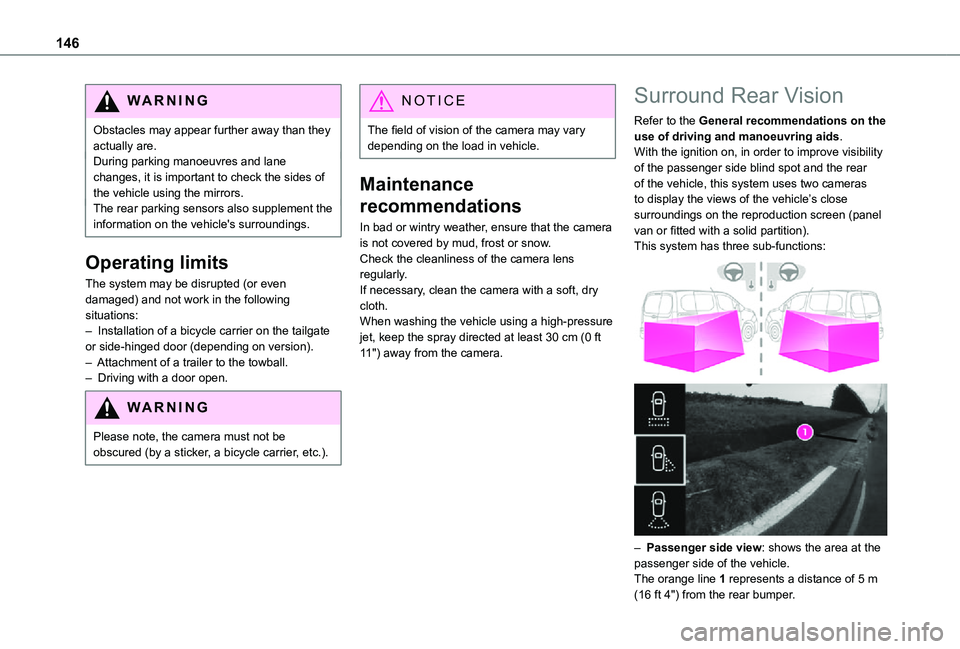
Refer to the General recommendations on the use of driving and manoeuvring aids.With the ignition on, in order to improve visibility of the passenger side blind spot and the rear of the vehicle, this system uses two cameras to display the views of the vehicle’s close surroundings on the reproduction screen (panel van or fitted with a solid partition).This system has three sub-functions:
– Passenger side view: shows the area at the passenger side of the vehicle.The orange line 1 represents a distance of 5 m (16 ft 4") from the rear bumper.
Page 148 of 272
148
WARNI NG
Obstacles may appear further away than they actually are.During parking manoeuvres and lane changes, it is important to check the sides of the vehicle using the mirrors.The rear parking sensors also supplement the information on the vehicle's surroundings.
Activation / Deactivation
The system starts when the ignition is switched on.
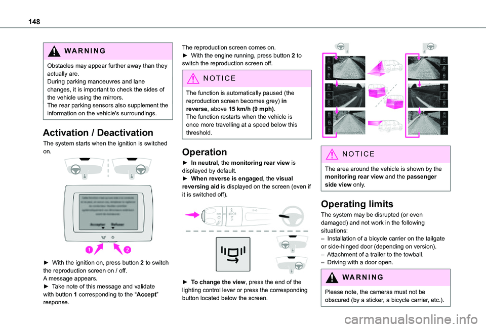
► With the ignition on, press button 2 to switch the reproduction screen on / off.
A message appears.► Take note of this message and validate with button 1 corresponding to the “Accept” response.
The reproduction screen comes on.► With the engine running, press button 2 to switch the reproduction screen off.
NOTIC E
The function is automatically paused (the reproduction screen becomes grey) in reverse, above 15 km/h (9 mph).The function restarts when the vehicle is
once more travelling at a speed below this threshold.
Operation
► In neutral, the monitoring rear view is displayed by default.► When reverse is engaged, the visual reversing aid is displayed on the screen (even if it is switched off).
► To change the view, press the end of the lighting control lever or press the corresponding button located below the screen.
NOTIC E
The area around the vehicle is shown by the monitoring rear view and the passenger side view only.
Operating limits
The system may be disrupted (or even damaged) and not work in the following situations:– Installation of a bicycle carrier on the tailgate or side-hinged door (depending on version).– Attachment of a trailer to the towball.– Driving with a door open.
WARNI NG
Please note, the cameras must not be obscured (by a sticker, a bicycle carrier, etc.).
Page 172 of 272
172
Spare wheel
Procedure for changing a damaged wheel with the spare wheel using the tools provided with the vehicle.
NOTIC E
For more information on the Tool kit, refer to the corresponding section.
► Park the vehicle, taking care to avoid obstructing traffic, and apply the parking brake.► Follow the safety instructions (hazard warning lamps, warning triangle, wearing high visibility vest, etc.) according to the legislation in force in the country where you are driving.► Switch off the ignition.
Access to the spare wheel
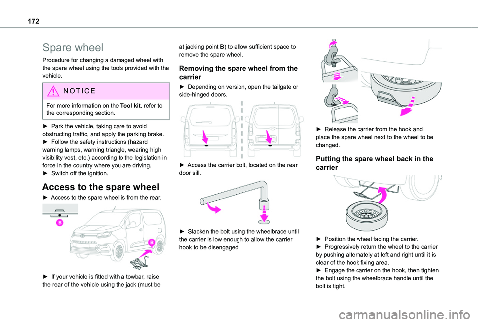
► Access to the spare wheel is from the rear.
► If your vehicle is fitted with a towbar, raise the rear of the vehicle using the jack (must be
at jacking point B) to allow sufficient space to remove the spare wheel.
Removing the spare wheel from the
carrier
► Depending on version, open the tailgate or side-hinged doors.
► Access the carrier bolt, located on the rear door sill.
► Slacken the bolt using the wheelbrace until the carrier is low enough to allow the carrier hook to be disengaged.
► Release the carrier from the hook and place the spare wheel next to the wheel to be changed.
Putting the spare wheel back in the
carrier
► Position the wheel facing the carrier.► Progressively return the wheel to the carrier by pushing alternately at left and right until it is clear of the hook fixing area.► Engage the carrier on the hook, then tighten the bolt using the wheelbrace handle until the bolt is tight.
Page 179 of 272
179
In the event of a breakdown
8
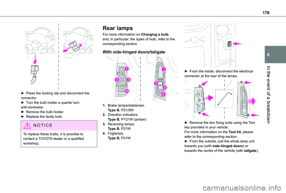
► Press the locking clip and disconnect the connector.► Turn the bulb holder a quarter turn anti-clockwise.► Remove the bulb holder.► Replace the faulty bulb.
NOTIC E
To replace these bulbs, it is possible to contact a TOYOTA dealer or a qualified workshop.
Rear lamps
For more information on Changing a bulb and, in particular, the types of bulb, refer to the corresponding section.
With side-hinged doors/tailgate
1.Brake lamps/sidelamps.Type B, P21/5W
2.Direction indicators.Type B, PY21W (amber)
3.Reversing lamps.Type B, P21W
4.Foglamps.Type B, P21W
► From the inside, disconnect the electrical connector at the rear of the lamps.
► Remove the two fixing bolts using the Torx key provided in your vehicle.For more information on the Tool kit, please refer to the corresponding section.► From the outside, pull the whole lamp unit towards you (with side-hinged doors) or towards the centre of the vehicle (with tailgate).
Page 180 of 272
180
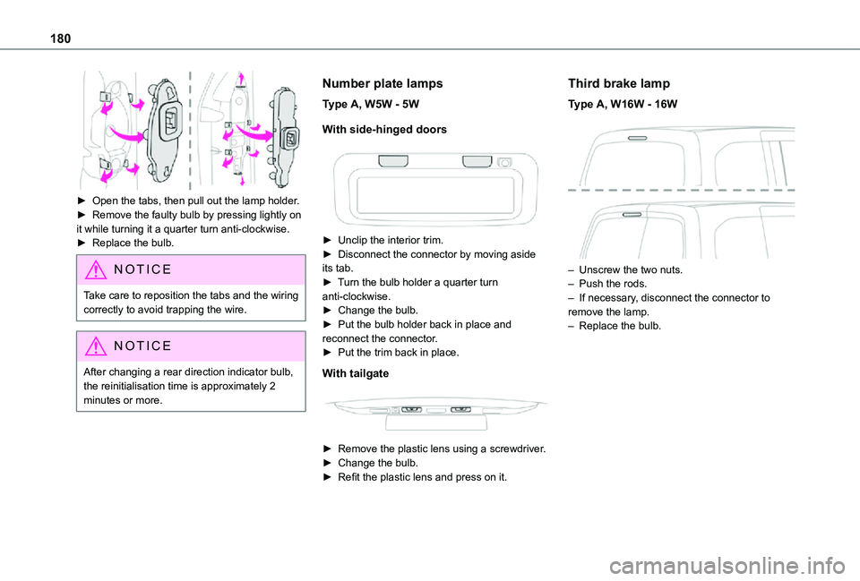
► Open the tabs, then pull out the lamp holder.► Remove the faulty bulb by pressing lightly on it while turning it a quarter turn anti-clockwise.► Replace the bulb.
NOTIC E
Take care to reposition the tabs and the wiring correctly to avoid trapping the wire.
NOTIC E
After changing a rear direction indicator bulb, the reinitialisation time is approximately 2
minutes or more.
Number plate lamps
Type A, W5W - 5W
With side-hinged doors
► Unclip the interior trim.► Disconnect the connector by moving aside its tab.► Turn the bulb holder a quarter turn anti-clockwise.► Change the bulb.► Put the bulb holder back in place and reconnect the connector.► Put the trim back in place.
With tailgate
► Remove the plastic lens using a screwdriver.► Change the bulb.► Refit the plastic lens and press on it.
Third brake lamp
Type A, W16W - 16W
– Unscrew the two nuts.– Push the rods.– If necessary, disconnect the connector to remove the lamp.– Replace the bulb.
Page 185 of 272
185
In the event of a breakdown
8
WARNI NG
Follow the instructions provided by the manufacturer of the charger.Never reverse polarities.
NOTIC E
It is not necessary to disconnect the battery.
► Switch off the ignition.► Switch off all electrical consumers (audio system, lighting, wipers, etc.).
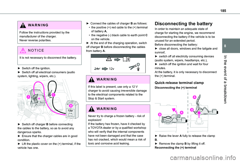
► Switch off charger B before connecting the cables to the battery, so as to avoid any dangerous sparks.
► Ensure that the charger cables are in good condition.► Lift the plastic cover on the (+) terminal, if the vehicle has one.
► Connect the cables of charger B as follows:• the positive (+) red cable to the (+) terminal of battery A,• the negative (-) black cable to earth point C on the vehicle.► At the end of the charging operation, switch off charger B before disconnecting the cables from battery A.
24v 12v
WARNI NG
If this label is present, use only a 12 V charger to avoid causing irreversible damage to the electrical components related to the Stop & Start system.
WARNI NG
Never try to charge a frozen battery - risk of explosion!If the battery has frozen, have it checked by a TOYOTA dealer or by a qualified workshop who will verify that the internal components have not been damaged and that the case has not cracked, which would mean a risk of toxic and corrosive acid leaking.
Disconnecting the battery
In order to maintain an adequate state of charge for starting the engine, we recommend disconnecting the battery if the vehicle is to be unused for an extended period.Before disconnecting the battery:► close all doors, windows and the tailgate and sunroof,► switch off all electricity consuming devices (audio system, wipers, headlamps, etc.),► switch off the ignition and wait for four minutes.At the battery, it is only necessary to disconnect the (+) terminal.
Quick-release terminal clamp
Disconnecting the (+) terminal
► Raise the lever A fully to release the clamp B.► Remove the clamp B by lifting it off.Reconnecting the (+) terminal
Page 190 of 272
190
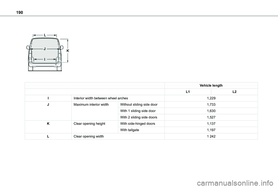
Vehicle length
L1L2
IInterior width between wheel arches1,229
JMaximum interior widthWithout sliding side door1,733
With 1 sliding side door1,630
With 2 sliding side doors1,527
KClear opening heightWith side-hinged doors1,137
With tailgate1,197
LClear opening width1 242