2021 RAM PROMASTER hazard
[x] Cancel search: hazardPage 6 of 288

4
DRIVING TIPS ........................................................86 Driving On Slippery Surfaces ...................... 86
Driving Through Water ................................ 86
MULTIMEDIA
UCONNECT SYSTEMS ..........................................88
CYBERSECURITY ..................................................88UCONNECT SETTINGS ..........................................89 Uconnect 3/3 NAV Settings ........................ 90
UCONNECT INTRODUCTION.................................98
Identifying Your Radio ................................. 98
Safety And General Information ...............100
UCONNECT MODES ........................................... 101
Radio Mode ................................................101
Media Mode ...............................................109Phone Mode ..............................................112
NAVIGATION MODE — IF EQUIPPED ................ 124
Operating Navigation Mode —
If Equipped .................................................124
STEERING WHEEL AUDIO CONTROLS ........... 146
Radio Operation .........................................146
Player Operation ........................................146
RAM TELEMATICS - IF EQUIPPED .................... 146
Ram Telematics General Information ......147
RADIO OPERATION AND MOBILE PHONES ... 148
Regulatory And Safety Information........... 148
SAFETY
SAFETY FEATURES .............................................149Anti-Lock Brake System (ABS) .................. 149Electronic Brake Control (EBC) System ... 150
AUXILIARY DRIVING SYSTEMS.........................155
Blind Spot Monitoring (BSM) —
If Equipped ................................................ 155 Forward Collision Warning (FCW) With
Mitigation — If Equipped............................ 159 Tire Pressure Monitoring
System (TPMS) ........................................... 161
OCCUPANT RESTRAINT SYSTEMS .................. 164
Occupant Restraint Systems Features .... 164
Important Safety Precautions ................... 164
Seat Belt Systems ..................................... 165
Supplemental Restraint
Systems (SRS)............................................ 172 Child Restraints ......................................... 181
SAFETY TIPS ...................................................... 186
Transporting Passengers .......................... 186Transporting Pets ..................................... 187
Safety Checks You Should Make Inside
The Vehicle ................................................ 187 Periodic Safety Checks You Should
Make Outside The Vehicle ........................ 188 Exhaust Gas ............................................... 189Carbon Monoxide Warnings ...................... 189
IN CASE OF EMERGENCY
HAZARD WARNING FLASHERS ....................... 190
JACKING AND TIRE CHANGING ....................... 190 Preparations For Jacking .......................... 191
Jack Location ............................................. 191
Spare Tire Removal ................................... 193
Jacking Instructions................................... 194
Wheel Covers ............................................. 197
TIRE SERVICE KIT — IF EQUIPPED ................... 197
Tire Service Kit Storage............................. 198
Tire Service Kit Components And
Operation ................................................... 198 Tire Service Kit Usage Precautions .......... 198Sealing A Tire With Tire Service Kit .......... 200
JUMP STARTING ................................................ 203
Preparations For Jump Start ..................... 203
Jump Starting Procedure .......................... 204
Battery Location ........................................ 206
IF YOUR ENGINE OVERHEATS ......................... 206
GEAR SELECTOR OVERRIDE ........................... 207
FREEING A STUCK VEHICLE ............................ 208
TOWING A DISABLED VEHICLE ........................ 209
Automatic Transmission............................ 210
ENHANCED ACCIDENT RESPONSE
SYSTEM (EARS).................................................. 210
EVENT DATA RECORDER (EDR) ....................... 210
21_VF_OM_EN_USC_t.book Page 4
Page 9 of 288

7
SYMBOLS KEY
WARNINGS AND CAUTIONS
This Owner’s Manual contains WARNINGS against operating procedures
that could result in a collision, bodily injury, and/or death. It also contains
CAUTIONS against procedures that could result in damage to your vehicle. If you do not read this entire Owner’s Manual, you may miss important
information. Observe all Warnings and Cautions.
VAN CONVERSIONS/CAMPERS
The New Vehicle Limited Warranty does not apply to body modifications or
special equipment installed by van conversion/camper manufacturers/
body builders. US residents refer to the Warranty Information, Section
2.1.C. Canadian residents refer to the “What Is Not Covered” section of
the Warranty Information. Such equipment includes video monitors, DVD/
Blu-Ray™, heaters, stoves, refrigerators, etc. For warranty coverage and
service on these items, contact the applicable manufacturer.
Operating instructions for the special equipment installed by the
conversion/camper manufacturer should also be supplied with your
vehicle. For any additional instructions, please contact your conversion/
camper manufacturer.
To obtain dimensional and technical specifications for your vehicle, refer
to the Body Builder’s Guide at https://www.ramtrucks.com/
ram-commercial/body-builders-guide.html.
VEHICLE MODIFICATIONS/ALTERATIONS
WARNING!
Indicates a potentially hazardous situation,
which if not avoided, could result in death or
serious injury.
CAUTION! An unsafe practice which may result in personal
injury or damage to the vehicle.
NOTE: A suggestion which will improve installation,
operation, and reliability. If not followed, may
result in damage.
TIP: General ideas/solutions/suggestions on easier
use of the product or functionality.
PAGE REFERENCE
ARROW
Follow this reference for additional information
on a particular feature.
FOOTNOTE Supplementary and relevant information
pertaining to the topic.
WARNING!
Any modifications or alterations to this vehicle could seriously affect its
roadworthiness and safety and may lead to a collision resulting in
serious injury or death.
1
21_VF_OM_EN_USC_t.book Page 7
Page 13 of 288

GETTING TO KNOW YOUR VEHICLE11
Replacing The Battery In The Key Fob
The recommended replacement battery is
CR2032.
NOTE:
Customers are recommended to use a
battery obtained from Mopar. Aftermarket
coin battery dimensions may not meet the
original OEM coin battery dimensions.
Perchlorate Material – special handling may
apply. See www.dtsc.ca.gov/hazard-
ouswaste/perchlorate.
1. Push the mechanical key release button and release the mechanical key to access
the battery case screw located on the side
of the key fob.
2. Rotate the screw located on the side of the key fob using a small screwdriver.
Key Fob Screw Location
3. Take out the battery case. Remove and replace the battery observing its polarity.
4. Refit the battery case inside the key fob and turn the screw to lock it into place.
Programming And Requesting Additional
Key Fobs
Programming the key fob may be performed by
an authorized dealer.
NOTE:
Once a key fob is programmed to a vehicle, it
cannot be re-purposed and reprogrammed to
another vehicle. Duplication of keys may be performed at an
authorized dealer. The VIN is required for
authorized dealer replacement of keys.
NOTE:
Only keys that have been programmed to the
vehicle electronics can be used to start the
vehicle. Once a Sentry Key has been
programmed to a vehicle, it cannot be
programmed to any other vehicle. When having
the Sentry Key Immobilizer system serviced,
bring all vehicle keys with you to an authorized
dealer.
WARNING!
Always remove the key fobs from the
vehicle and lock all doors when leaving the
vehicle unattended.
Always remember to place the ignition in
the OFF mode.2
21_VF_OM_EN_USC_t.book Page 11
Page 79 of 288

STARTING AND OPERATING77
TIRE SIZE
The tire size on the Vehicle Certification Label
represents the actual tire size on your vehicle.
Replacement tires must be equal to the load
capacity of this tire size.
RIM SIZE
This is the rim size that is appropriate for the tire
size listed.
INFLATION PRESSURE
This is the cold tire inflation pressure for your
vehicle for all loading conditions up to full Gross
Axle Weight Rating (GAWR).
CURB WEIGHT
The curb weight of a vehicle is defined as the
total weight of the vehicle with all fluids,
including vehicle fuel, at full capacity
conditions, and with no occupants or cargo
loaded into the vehicle. The front and rear curb
weight values are determined by weighing your
vehicle on a commercial scale before any
occupants or cargo are added.
OVERLOADING
The load carrying components (axle, springs,
tires, wheels, etc.) of your vehicle will provide
satisfactory service as long as you do not
exceed the Gross Vehicle Weight Rating (GVWR)
and the front and rear Gross Axle Weight Rating
(GAWR).
The best way to figure out the total weight of
your vehicle is to weigh it when it is fully loaded
and ready for operation. Weigh it on a
commercial scale to ensure that it is not over
the GVWR.
Figure out the weight on the front and rear axle
of the vehicle separately. It is important that you
distribute the load evenly over the front and rear
axles.
Overloading can cause potential safety hazards
and shorten useful service life. Heavier axles or
suspension components do not necessarily
increase the vehicle's GVWR.
LOADING
To load your vehicle properly, first figure out its
empty weight, axle-by-axle and side-by-side.
Store heavier items down low and be sure you
distribute their weight as evenly as possible.
Stow all loose items securely before driving. If
weighing the loaded vehicle shows that you
have exceeded either Gross Axle Weight Rating
(GAWR), but the total load is within the specified
Gross Vehicle Weight Rating (GVWR), you must
redistribute the weight. Improper weight
distribution can have an adverse effect on the
way your vehicle steers and handles and the
way the brakes operate.
NOTE:
Refer to the “Vehicle Certification Label” affixed
to the rear of the driver's door for your vehicle's
GVWR and GAWRs.
4
21_VF_OM_EN_USC_t.book Page 77
Page 153 of 288

SAFETY151
(Continued)
ESC uses sensors in the vehicle to determine
the vehicle path intended by the driver and
compares it to the actual path of the vehicle.
When the actual path does not match the
intended path, ESC applies the brake of the
appropriate wheel to assist in counteracting the
oversteer or understeer condition.ESC Operating Modes
ESC OFF button Location
The ESC OFF button is located in the center
switch bank, next to the hazard flasher switch.
ESC On
This mode is the normal operating mode for ESC
equipped vehicles. Whenever the vehicle is
started, the ESC system will be in this mode.
This mode should be used for most driving
situations. ESC should only be turned off for
specific reasons as noted below.
WARNING!
Electronic Stability Control (ESC) cannot
prevent the natural laws of physics from
acting on the vehicle, nor can it increase
the traction afforded by prevailing road
conditions. ESC cannot prevent accidents,
including those resulting from excessive
speed in turns, driving on very slippery
surfaces, or hydroplaning. ESC also cannot
prevent accidents resulting from loss of
vehicle control due to inappropriate driver
input for the conditions. Only a safe, atten -
tive, and skillful driver can prevent acci -
dents. The capabilities of an ESC equipped
vehicle must never be exploited in a reck -
less or dangerous manner which could
jeopardize the user’s safety or the safety of
others.
Vehicle modifications, or failure to properly
maintain your vehicle, may change the
handling characteristics of your vehicle,
and may negatively affect the performance
of the ESC system. Changes to the steering
system, suspension, braking system, tire
type and size or wheel size may adversely
affect ESC performance. Improperly
inflated and unevenly worn tires may also
degrade ESC performance. Any vehicle
modification or poor vehicle maintenance
that reduces the effectiveness of the ESC
system can increase the risk of loss of
vehicle control, vehicle rollover, personal
injury and death.
WARNING! (Continued)
6
21_VF_OM_EN_USC_t.book Page 151
Page 161 of 288

SAFETY159
NOTE:
Whenever an audible alert is requested by the
BSM system, the radio is also muted.
When the system is in RCP, the system shall
respond with both visual and audible alerts
when a detected object is present. Whenever
an audible alert is requested, the radio is also
muted. Turn/hazard signal status is ignored;
the RCP state always requests the chime.
Blind Spot Alert Off
When the BSM system is turned off there will be
no visual or audible alerts from either the BSM
or RCP systems.
NOTE:
The BSM system will store the current operating
mode when the vehicle is shut off. Each time
the vehicle is started the previously stored
mode will be recalled and used.
FORWARD COLLISION WARNING (FCW)
W
ITH MITIGATION — IF EQUIPPED
The FCW with Mitigation system provides the
driver with audible warnings, visual warnings
(within the instrument cluster display), and may
apply a brake jerk to warn the driver when it
detects a potential frontal collision. The warnings and limited braking are intended
to provide the driver with enough time to react,
avoid or mitigate the potential collision.
NOTE:
FCW monitors the information from the forward
looking sensors as well as the Electronic Brake
Controller (EBC), to calculate the probability of a
forward collision. When the system determines
that a forward collision is probable, the driver
will be provided with audible and visual warn-
ings as well as a possible brake jerk warning.
If the driver does not take action based upon
these progressive warnings, then the system
will provide a limited level of active braking to
help slow the vehicle and mitigate the potential
forward collision. If the driver reacts to the warn
-
ings by braking and the system determines that
the driver intends to avoid the collision by
braking but has not applied sufficient brake
force, the system will compensate and provide
additional brake force as required.
If a FCW with Mitigation event begins at a speed
below 26 mph (42 km/h), the system may
provide the maximum braking possible to miti -
gate the potential forward collision. Vehicles
With Automatic Transmission: After the end of the intervention of automatic braking, the trans
-
mission may remain in last gear stored — there -
fore the vehicle could lurch forward, once the
brakes release a few seconds later. If the
Forward Collision Warning with Mitigation event
stops the vehicle completely, the system will
hold the vehicle at standstill for two seconds
and then release the brakes.
FCW Message
When the system determines a collision with
the vehicle in front of you is no longer probable,
the warning message will be deactivated.
6
21_VF_OM_EN_USC_t.book Page 159
Page 181 of 288

SAFETY179
(Continued)
Fuel Cut Off Switch
Your vehicle is equipped with a Fuel Cut Off
switch. In the event of an accident, if the
communication network remains intact, and
the power remains intact, depending on the
nature of the event, the Fuel Cut Off Switch may
perform the following functions:
Cut off fuel to the engine and turn off the
engine.
Flash hazard lights as long as the battery has
power or until the hazard light button is
pressed. The hazard lights can be deacti -
vated by pressing the hazard light button.
Turn on the interior lights, which remain on
as long as the battery has power.
Unlock the power door locks.
NOTE:
After an accident, remember to cycle the igni -
tion to the STOP (OFF/LOCK) position and
remove the key from the ignition switch to avoid
draining the battery. Carefully check the vehicle
for fuel leaks in the engine compartment and on
the ground near the engine compartment and
fuel tank before resetting the system and
starting the engine. If there are no fuel leaks or damage to the vehicle electrical devices (e.g.
headlights) after an accident, reset the Fuel Cut
Off Switch by following the procedure described
below. If you have any doubt, contact an autho
-
rized dealer.
Fuel Cut Off Switch Reset Procedure
In order to reset the Fuel Cut Off Switch after an
event push the “A” Button located underneath
the instrument panel on the passenger side.
Fuel Cut Off Switch
Maintaining Your Air Bag System
WARNING!
If, after an accident, you smell fuel or see
leaks from the fuel system, do not reset the
Fuel Cut Off Switch to avoid the risk of fire.
Before resetting the Fuel Cut Off Switch,
carefully check for fuel leaks or damage to
the vehicle electrical devices (e.g.
headlights).
WARNING!
Modifications to any part of the air bag
system could cause it to fail when you need
it. You could be injured if the air bag system
is not there to protect you. Do not modify
the components or wiring, including adding
any kind of badges or stickers to the
steering wheel hub trim cover or the upper
passenger side of the instrument panel. Do
not modify the front bumper, vehicle body
structure, or add aftermarket side steps or
running boards.6
21_VF_OM_EN_USC_t.book Page 179
Page 192 of 288
190
IN CASE OF EMERGENCY
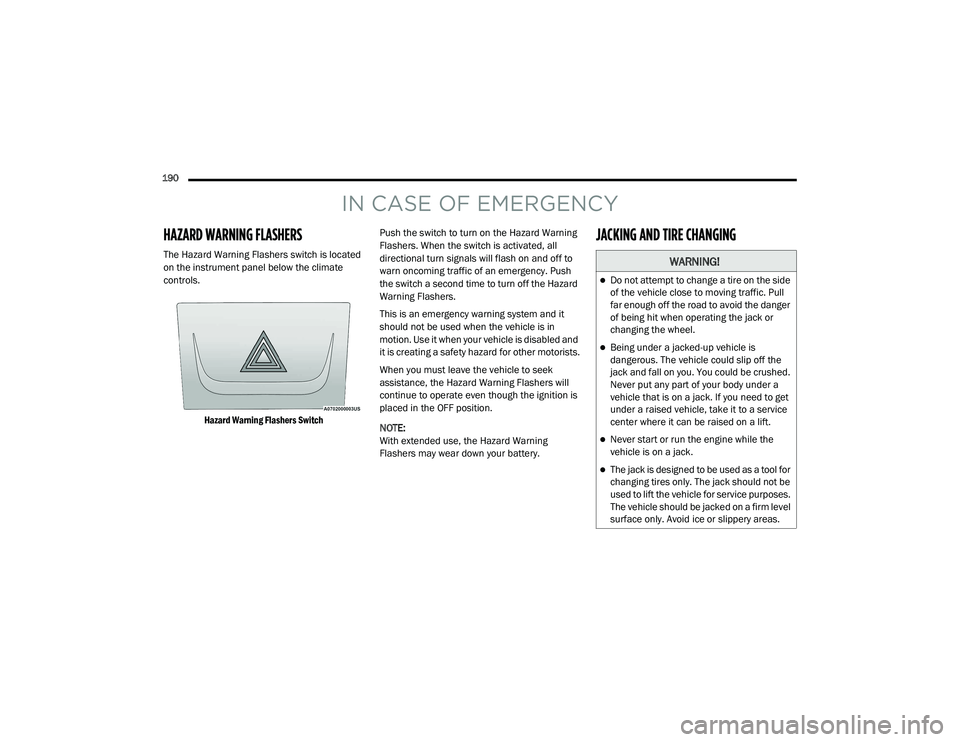
HAZARD WARNING FLASHERS
The Hazard Warning Flashers switch is located
on the instrument panel below the climate
controls.
Hazard Warning Flashers Switch
Push the switch to turn on the Hazard Warning
Flashers. When the switch is activated, all
directional turn signals will flash on and off to
warn oncoming traffic of an emergency. Push
the switch a second time to turn off the Hazard
Warning Flashers.
This is an emergency warning system and it
should not be used when the vehicle is in
motion. Use it when your vehicle is disabled and
it is creating a safety hazard for other motorists.
When you must leave the vehicle to seek
assistance, the Hazard Warning Flashers will
continue to operate even though the ignition is
placed in the OFF position.
NOTE:
With extended use, the Hazard Warning
Flashers may wear down your battery.
JACKING AND TIRE CHANGING
WARNING!
Do not attempt to change a tire on the side
of the vehicle close to moving traffic. Pull
far enough off the road to avoid the danger
of being hit when operating the jack or
changing the wheel.
Being under a jacked-up vehicle is
dangerous. The vehicle could slip off the
jack and fall on you. You could be crushed.
Never put any part of your body under a
vehicle that is on a jack. If you need to get
under a raised vehicle, take it to a service
center where it can be raised on a lift.
Never start or run the engine while the
vehicle is on a jack.
The jack is designed to be used as a tool for
changing tires only. The jack should not be
used to lift the vehicle for service purposes.
The vehicle should be jacked on a firm level
surface only. Avoid ice or slippery areas.
21_VF_OM_EN_USC_t.book Page 190