2021 PEUGEOT 5008 ESP
[x] Cancel search: ESPPage 187 of 292
185
Practical information
7Reduction) with a Diesel Particle Filter (DPF) for
the treatment of exhaust gases.
SCR system
Using a liquid called AdBlue® that contains
urea, a catalytic converter turns up to 85% of
the nitrogen oxides (NOx) into nitrogen and
water, which are harmless to health and the
environment.
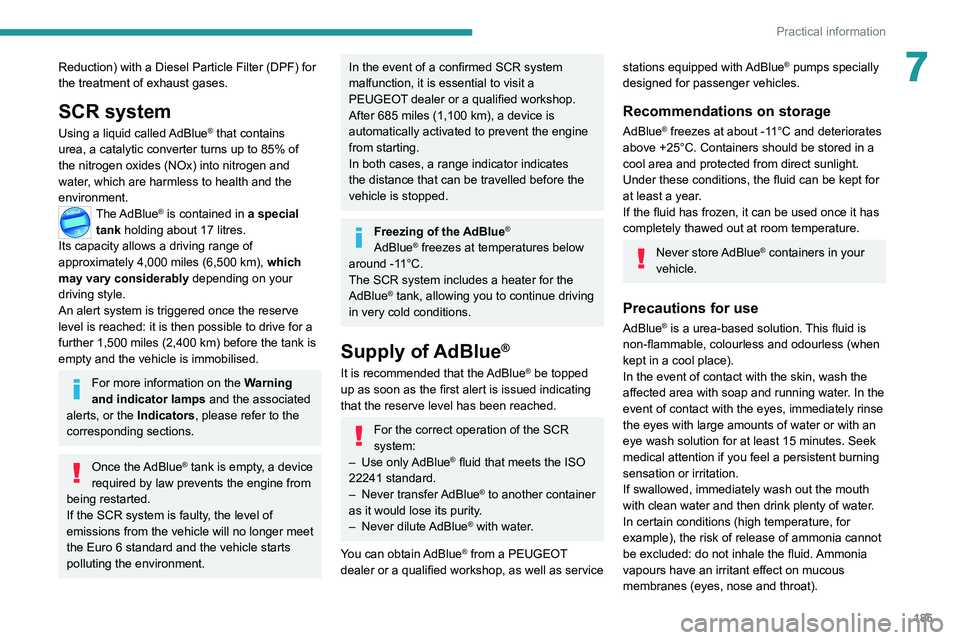
The AdBlue® is contained in a special
tank holding about 17 litres.
Its capacity allows a driving range of
approximately 4,000
miles (6,500 km),
which
may vary considerably depending on your
driving style.
An alert system is triggered once the reserve
level is reached: it is then possible to drive for a
further 1,500 miles (2,400
km) before the tank is
empty and the vehicle is immobilised.
For more information on the Warning
and indicator lamps and the associated
alerts, or the Indicators, please refer to the
corresponding sections.
Once the AdBlue® tank is empty, a device
required by law prevents the engine from
being restarted.
If the SCR system is faulty, the level of
emissions from the vehicle will no longer meet
the Euro 6 standard and the vehicle starts
polluting the environment.
In the event of a confirmed SCR system
malfunction, it is essential to visit a
PEUGEOT dealer or a qualified workshop.
After 685 miles (1,100 km), a device is
automatically activated to prevent the engine
from starting.
In both cases, a range indicator indicates
the distance that can be travelled before the
vehicle is stopped.
Freezing of the AdBlue®
AdBlue® freezes at temperatures below
around -11°C.
The SCR system includes a heater for the
AdBlue
® tank, allowing you to continue driving
in very cold conditions.
Supply of AdBlue®
It is recommended that the AdBlue® be topped
up as soon as the first alert is issued indicating
that the reserve level has been reached.
For the correct operation of the SCR
system:
–
Use
only AdBlue
® fluid that meets the ISO
22241 standard.
–
Never
transfer AdBlue
® to another container
as it would lose its purity.
–
Never
dilute AdBlue
® with water.
You can obtain AdBlue
® from a PEUGEOT
dealer or a qualified workshop, as well as service
stations equipped with AdBlue® pumps specially
designed for passenger vehicles.
Recommendations on storage
AdBlue® freezes at about -11°C and deteriorates
above +25°C. Containers should be stored in a
cool area and protected from direct sunlight.
Under these conditions, the fluid can be kept for
at least a year.
If the fluid has frozen, it can be used once it has
completely thawed out at room temperature.
Never store AdBlue® containers in your
vehicle.
Precautions for use
AdBlue® is a urea-based solution. This fluid is
non-flammable, colourless and odourless (when
kept in a cool place).
In the event of contact with the skin, wash the
affected area with soap and running water. In the
event of contact with the eyes, immediately rinse
the eyes with large amounts of water or with an
eye wash solution for at least 15 minutes. Seek
medical attention if you feel a persistent burning
sensation or irritation.
If swallowed, immediately wash out the mouth
with clean water and then drink plenty of water.
In certain conditions (high temperature, for
example), the risk of release of ammonia cannot
be excluded: do not inhale the fluid. Ammonia
vapours have an irritant effect on mucous
membranes (eyes, nose and throat).
Page 191 of 292
189
In the event of a breakdown
8Warning triangle
This reflective and dismantlable device is to be
installed on the side of the road when a vehicle
is broken down or damaged.
Before getting out of the vehicle
Turn on the hazard warning lamps, then
put on the safety vest to assemble and install
the triangle.
Storage compartment
There is a compartment in the interior trim of the
tailgate to store a warning triangle.
►
After opening the tailgate, release the cover
by turning the screw a quarter turn to the left.
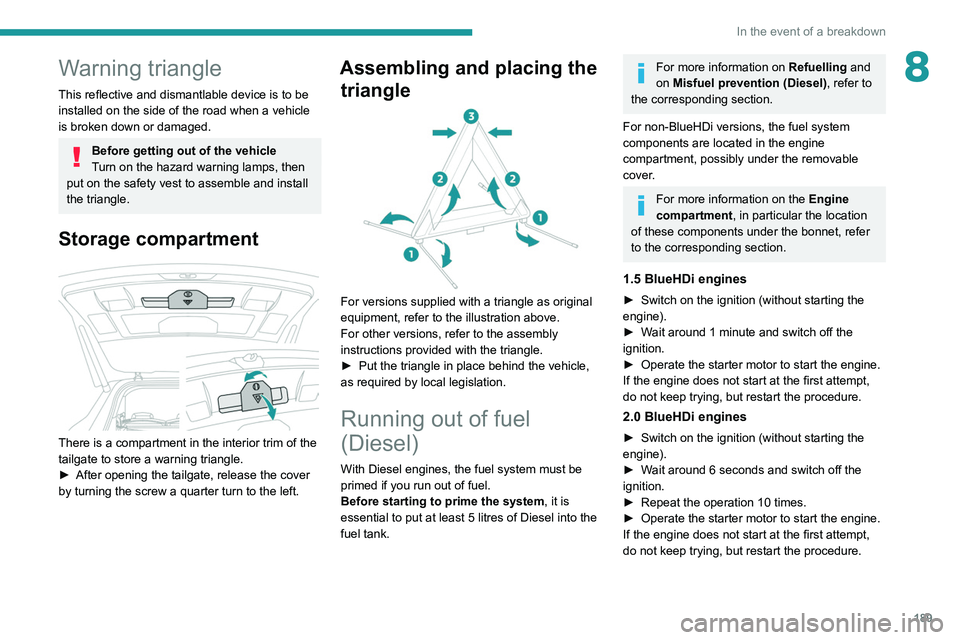
Assembling and placing the triangle
For versions supplied with a triangle as original
equipment, refer to the illustration above.
For other versions, refer to the assembly
instructions provided with the triangle.
►
Put the triangle in place behind the vehicle,
as required by local legislation.
Running out of fuel
(Diesel)
With Diesel engines, the fuel system must be
primed if you run out of fuel.
Before starting to prime the system, it is
essential to put at least 5 litres of Diesel into the
fuel tank.
For more information on Refuelling and
on Misfuel prevention (Diesel), refer to
the corresponding section.
For non-BlueHDi versions, the fuel system
components are located in the engine
compartment, possibly under the removable
cover.
For more information on the Engine
compartment, in particular the location
of these components under the bonnet, refer
to the corresponding section.
1.5 BlueHDi engines
► Switch on the ignition (without starting the
engine).
►
W
ait around 1 minute and switch off the
ignition.
►
Operate the starter motor to start the engine.
If the engine does not start at the first attempt,
do not keep trying, but restart the procedure.
2.0 BlueHDi engines
► Switch on the ignition (without starting the
engine).
►
W
ait around 6 seconds and switch off the
ignition.
►
Repeat the operation 10
times.
►
Operate the starter motor to start the engine.
If the engine does not start at the first attempt,
do not keep trying, but restart the procedure.
Page 193 of 292
191
In the event of a breakdown
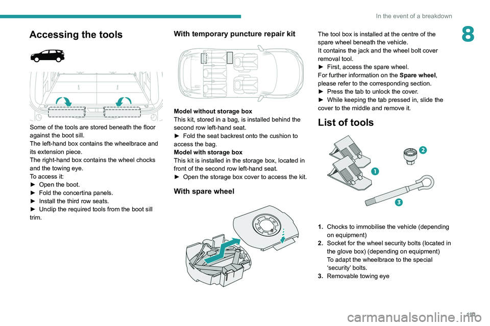
8Accessing the tools
Some of the tools are stored beneath the floor
against the boot sill.
The left-hand box contains the wheelbrace and
its extension piece.
The right-hand box contains the wheel chocks
and the towing eye.
To access it:
►
Open the boot.
►
Fold the concertina panels.
►
Install the third row seats.
►
Unclip the required tools from the boot sill
trim.
With temporary puncture repair kit
Model without storage box
This kit, stored in a bag, is installed behind the
second row left-hand seat.
►
Fold the seat backrest onto the cushion to
access the bag.
Model with storage box
This kit is installed in the storage box, located in
front of the second row left-hand seat.
►
Open the storage box cover to access the kit.
With spare wheel
The tool box is installed at the centre of the
spare wheel beneath the vehicle.
It contains the jack and the wheel bolt cover
removal tool.
►
First, access the spare wheel.
For further information on the
Spare wheel,
please refer to the corresponding section.
►
Press the tab to unlock the cover
.
►
While keeping the tab pressed in, slide the
cover to the middle and remove it.
List of tools
1. Chocks to immobilise the vehicle (depending
on equipment)
2. Socket for the wheel security bolts (located in
the glove box) (depending on equipment)
To adapt the wheelbrace to the special
‘security’ bolts.
3. Removable towing eye
Page 194 of 292
192
In the event of a breakdown
The vehicle's electric system allows the connection of the compressor to the 12 V
power supply for long enough to repair a tyre
after a puncture.
Only the 12 V socket located at the front
of the vehicle can be used to power the
compressor.
For more information on the Tool kit,
refer to the corresponding section.
Tyre inflation pressures are indicated on this label.
For more information on Identification
markings, particularly this label, refer to the
corresponding section.
Should the pressure of one or more tyres
be adjusted, it is necessary to reinitialise
the under-inflation detection system.
For more information on Tyre under-inflation
detection, refer to the corresponding section.
Repair procedure
Do not remove any foreign bodies (e.g.
nail, screw) which have penetrated into
the tyre.
For more information on Towing the vehicle
and using the removable towing eye, refer to the
corresponding section.
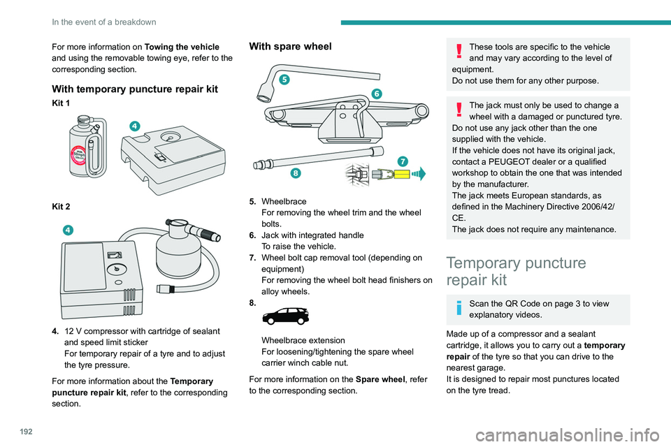
With temporary puncture repair kit
Kit 1
Kit 2
4. 12 V compressor with cartridge of sealant
and speed limit sticker
For temporary repair of a tyre and to adjust
the tyre pressure.
For more information about the Temporary
puncture repair kit, refer to the corresponding
section.
With spare wheel
5. Wheelbrace
For removing the wheel trim and the wheel
bolts.
6. Jack with integrated handle
To raise the vehicle.
7. Wheel bolt cap removal tool (depending on
equipment)
For removing the wheel bolt head finishers on
alloy wheels.
8.
Wheelbrace extension
For loosening/tightening the spare wheel
carrier winch cable nut.
For more information on the Spare wheel, refer
to the corresponding section.
These tools are specific to the vehicle and may vary according to the level of
equipment.
Do not use them for any other purpose.
The jack must only be used to change a wheel with a damaged or punctured tyre.
Do not use any jack other than the one
supplied with the vehicle.
If the vehicle does not have its original jack,
contact a PEUGEOT dealer or a qualified
workshop to obtain the one that was intended
by the manufacturer.
The jack meets European standards, as
defined in the Machinery Directive 2006/42/
CE.
The jack does not require any maintenance.
Temporary puncture repair kit
Scan the QR Code on page 3 to view
explanatory videos.
Made up of a compressor and a sealant
cartridge,
it allows you to carry out a temporary
repair of the tyre so that you can drive to the
nearest garage.
It is designed to repair most punctures located
on the tyre tread.
Page 195 of 292
193
In the event of a breakdown
8The vehicle's electric system allows the connection of the compressor to the 12 V
power supply for long enough to repair a tyre
after a puncture.
Only the 12 V socket located at the front
of the vehicle can be used to power the
compressor.
For more information on the Tool kit,
refer to the corresponding section.
Tyre inflation pressures are indicated on this label.
For more information on Identification
markings, particularly this label, refer to the
corresponding section.
Should the pressure of one or more tyres
be adjusted, it is necessary to reinitialise
the under-inflation detection system.
For more information on Tyre under-inflation
detection, refer to the corresponding section.
Repair procedure
Do not remove any foreign bodies (e.g.
nail, screw) which have penetrated into
the tyre. ►
Park the vehicle without obstructing traffic
and apply the parking brake.
►
Follow the safety instructions (hazard
warning lamps, warning triangle, high visibility
jacket, etc.) according to the legislation in force
in the country in which you are driving.
►
Switch the ignition off.
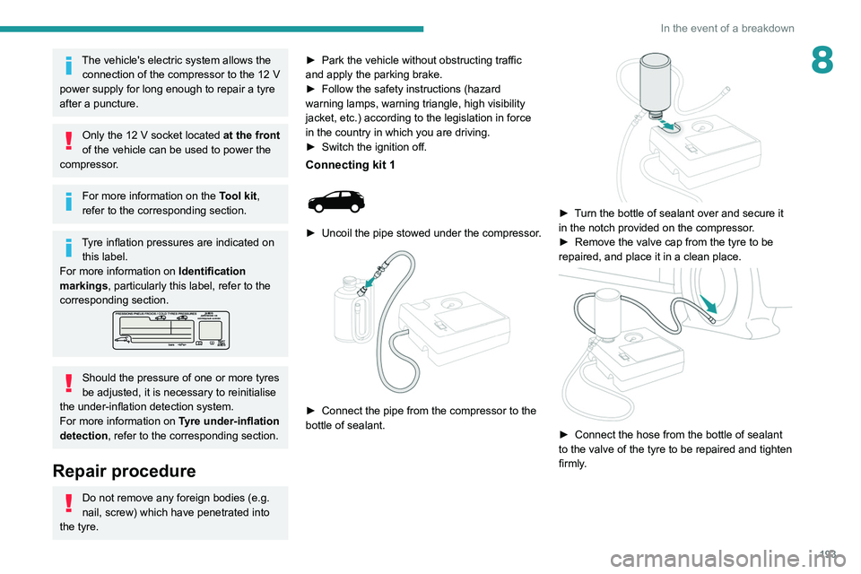
Connecting kit 1
► Uncoil the pipe stowed under the compressor.
► Connect the pipe from the compressor to the
bottle of sealant.
► Turn the bottle of sealant over and secure it
in the notch provided on the compressor.
►
Remove the valve cap from the tyre to be
repaired, and place it in a clean place.
► Connect the hose from the bottle of sealant
to the valve of the tyre to be repaired and tighten
firmly
.
Page 204 of 292
202
In the event of a breakdown
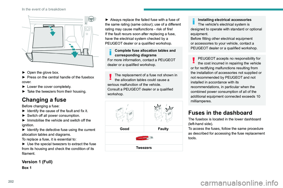
► Open the glove box.
► Press on the central handle of the fusebox
cover
.
►
Lower the cover completely
.
►
T
ake the tweezers from their housing.
Changing a fuse
Before changing a fuse:
► Identify the cause of the fault and fix it.
►
Switch off all power consumption.
►
Immobilise the vehicle and switch off the
ignition.
►
Identify the defective fuse using the current
allocation tables and diagrams.
T
o replace a fuse, it is essential to:
►
Use the special tweezers to extract the fuse
from its housing and check the condition of its
filament.
► Always replace the failed fuse with a fuse of
the same rating (same colour); use of a different
rating may cause malfunctions - risk of fire!
If the fault recurs soon after replacing a fuse,
have the electrical system checked by a
PEUGEOT
dealer or a qualified workshop.
Complete fuse allocation tables and
corresponding diagrams
For more information, contact a PEUGEOT
dealer or a qualified workshop.
The replacement of a fuse not shown in the allocation tables could cause a
serious malfunction of the vehicle.
Consult a PEUGEOT dealer or a qualified
workshop.
Good
Faulty
Tweezers
Installing electrical accessories
The vehicle's electrical system is
designed to operate with standard or optional
equipment.
Before fitting other electrical equipment
or accessories to your vehicle, contact a
PEUGEOT dealer or a qualified workshop.
PEUGEOT accepts no responsibility for
the cost incurred in repairing the vehicle
or for rectifying malfunctions resulting from
the installation of accessories not supplied or
not recommended by PEUGEOT and not
installed in accordance with its
recommendations, in particular when the
combined power consumption of all of the
additional equipment connected exceeds 10
milliamperes.
Fuses in the dashboard
The fusebox is located in the lower dashboard
(left-hand side).
To access the fuses, follow the same procedure
as described for accessing the fuse replacement
tools.
Version 1 (Full)
Box 1
Page 215 of 292
213
In the event of a breakdown
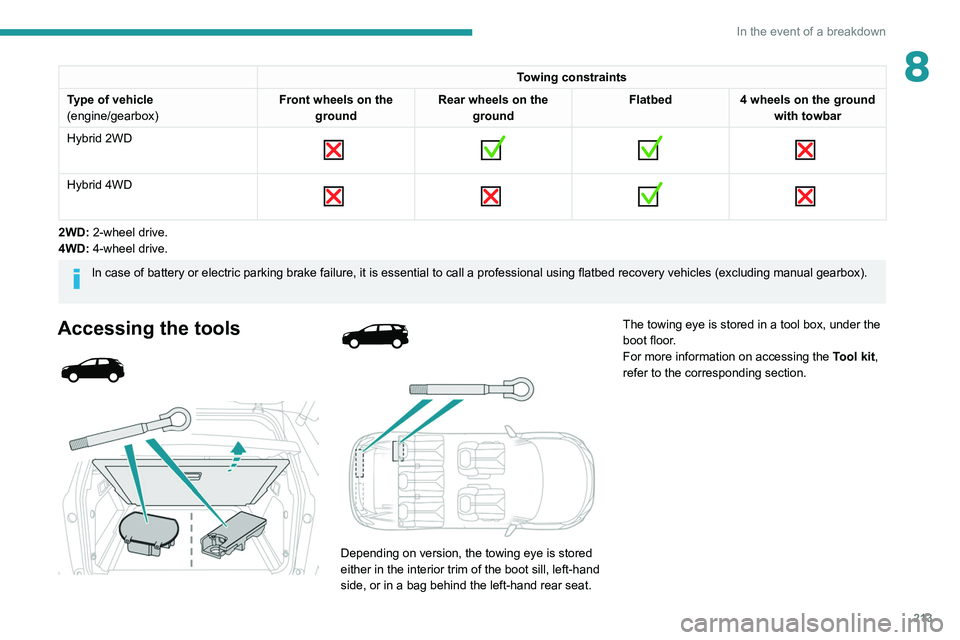
8Towing constraints
Type of vehicle
(engine/gearbox) Front wheels on the
ground Rear wheels on the
ground Flatbed
4 wheels on the ground
with towbar
Hybrid 2WD
Hybrid 4WD
2WD: 2-wheel drive.
4WD: 4-wheel drive.
In case of battery or electric parking brake failure, it is essential to call a p
rofessional using flatbed recovery vehicles (excluding manual gearbox).
Accessing the tools
Depending on version, the towing eye is stored
either in the interior trim of the boot sill, left-hand
side, or in a bag behind the left-hand rear seat. The towing eye is stored in a tool box, under the
boot floor.
For more information on accessing the
Tool kit,
refer to the corresponding section.
Page 217 of 292

215
Technical data
9Engine technical data and
towed loads
Engines
The engine characteristics are given in the
vehicle's registration document, as well as in
sales brochures.
Only the values available at the time of
publication are presented in the tables.
Contact a PEUGEOT dealer or a qualified
workshop to obtain missing values.
The maximum power corresponds to the value type-approved on a test bed, under
conditions defined by European legislation
(Directive 1999/99/EC).
For more information, contact a PEUGEOT
dealer or a qualified workshop.
Weights and towed loads
The weights and towed loads relating to
the vehicle are indicated on the registration
document, as well as in sales brochures.
These values are also indicated on the
manufacturer's plate or label.
For more information, contact a PEUGEOT
dealer or a qualified workshop.
The GTW (Gross Train Weight) and towed load
values indicated are valid up to a maximum
altitude of 1,000 metres. The towed load value
must be reduced by 10% for each additional
1,000 metres of altitude.
The maximum authorised nose weight
corresponds to the weight permitted on the
towball.
When exterior temperatures are high, the
vehicle performance may be limited in
order to protect the engine. When the exterior
temperature is higher than 37°C, reduce the
towed weight.
Towing even with a lightly loaded vehicle can adversely affect its road holding.
Braking distances are increased when towing
a trailer.
When using a vehicle to tow, never exceed
a speed of 62 mph (100
km/h) (observe the
local legislation in force).