2021 NISSAN TITAN stop
[x] Cancel search: stopPage 224 of 638

CONDITIONS THE REMOTE ENGINE
START WILL NOT WORK
The Remote Engine Start will not operate if
any of the following conditions are present:
• The ignition switch is placed in the ONposition.
• The hood is not securely closed.
• The hazard warning lights are on.
• The engine is still running. The engine must be completely stopped. Wait at
least 6 seconds if the engine goes from
running to off. This is not applicable when
extending engine run time.
• The
button is not pressed and held
for at least 2 seconds.
• The
button is not pressed and held
within 5 seconds of pressing the lock but-
ton.
• The brake is pressed.
• The doors are not closed and locked.
• The Key System Error Light remains solid in the vehicle information display.
• The alarm sounds due to illegal entry into the vehicle.
• Two Remote Engine Starts, or a single Remote Engine Start with an extension,
have already been used.
• The vehicle is not in P (Park). • There is a detected registered key already
inside of the vehicle.
• The remote start function has been switched to the OFF position in Vehicle
Settings for the vehicle information dis-
play. For additional information, see “Ve-
hicle information display” (P. 2-22).
The Remote Engine Start Mode (if so
equipped) may display a warning or indica-
tor in the vehicle information display. For
additional information, see “Vehicle infor-
mation display” (P. 2-22).
3-24Pre-driving checks and adjustments
Page 226 of 638

CAUTION
Be careful when opening and exiting
the driver’s side rear door if the fuel-
filler door is open. This may cause dam-
age to the driver’s side rear door or
fuel-filler door if you open fully and
they make contact.
GASOLINE FUEL ENGINES
WARNING
• Gasoline is extremely flammable and
highly explosive under certain condi-
tions. You could be burned or seri-
ously injured if it is misused or mis-
handled. Always stop the engine and
do not smoke or allow open flames
or sparks near the vehicle when
refueling. •
Do not attempt to top off the fuel
tank af ter the fuel pump nozzle
shuts off automatically. Continued
refueling may cause fuel overflow,
resulting in fuel spray and possibly a
fire.
• Use only an original equipment type
fuel-filler cap as a replacement. It has
a built-in safety valve needed for
proper operation of the fuel system
and emission control system. An in-
correct cap can result in a serious
malfunction and possible injury. It
could also cause the
Malfunc-
tion Indicator Light (MIL) to come on.
• Never pour fuel into the throttle body
to attempt to start your vehicle.
• Do not fill a portable fuel container
on a truck bed liner, rubber truck bed
mat or other insulating material.
Static electricity can cause an explo-
sion of flammable liquid, vapor or
gas in any vehicle or trailer. To reduce
the risk of serious injury or death
when filling portable fuel containers:
– Always place the container on the
ground when filling.
– Do not use electronic devices
when filling.LPD2594
King Cab® models only
LPD3100
3-26Pre-driving checks and adjustments
Page 236 of 638
Heated mirrors (if so equipped)
Some outside mirrors can be heated to
defrost, defog, or de-ice for improved vis-
ibility. For additional information, see “Rear
window and/or outside mirror defroster
switch” (P. 2-42).
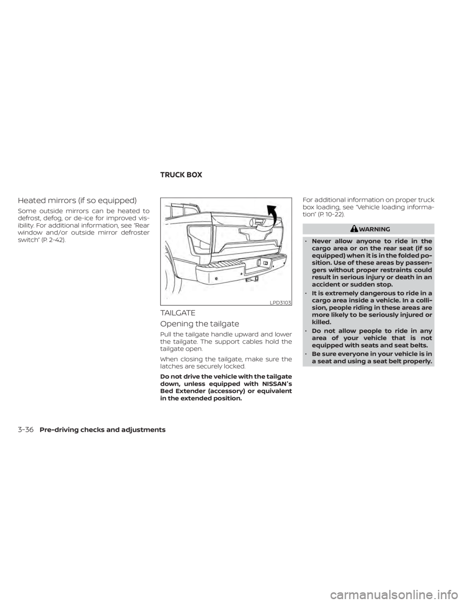
TAILGATE
Opening the tailgate
Pull the tailgate handle upward and lower
the tailgate. The support cables hold the
tailgate open.
When closing the tailgate, make sure the
latches are securely locked.
Do not drive the vehicle with the tailgate
down, unless equipped with NISSAN's
Bed Extender (accessory) or equivalent
in the extended position.For additional information on proper truck
box loading, see “Vehicle loading informa-
tion” (P. 10-22).
WARNING
• Never allow anyone to ride in the
cargo area or on the rear seat (if so
equipped) when it is in the folded po-
sition. Use of these areas by passen-
gers without proper restraints could
result in serious injury or death in an
accident or sudden stop.
• It is extremely dangerous to ride in a
cargo area inside a vehicle. In a colli-
sion, people riding in these areas are
more likely to be seriously injured or
killed.
• Do not allow people to ride in any
area of your vehicle that is not
equipped with seats and seat belts.
• Be sure everyone in your vehicle is in
a seat and using a seat belt properly.
LPD3103
TRUCK BOX
3-36Pre-driving checks and adjustments
Page 240 of 638
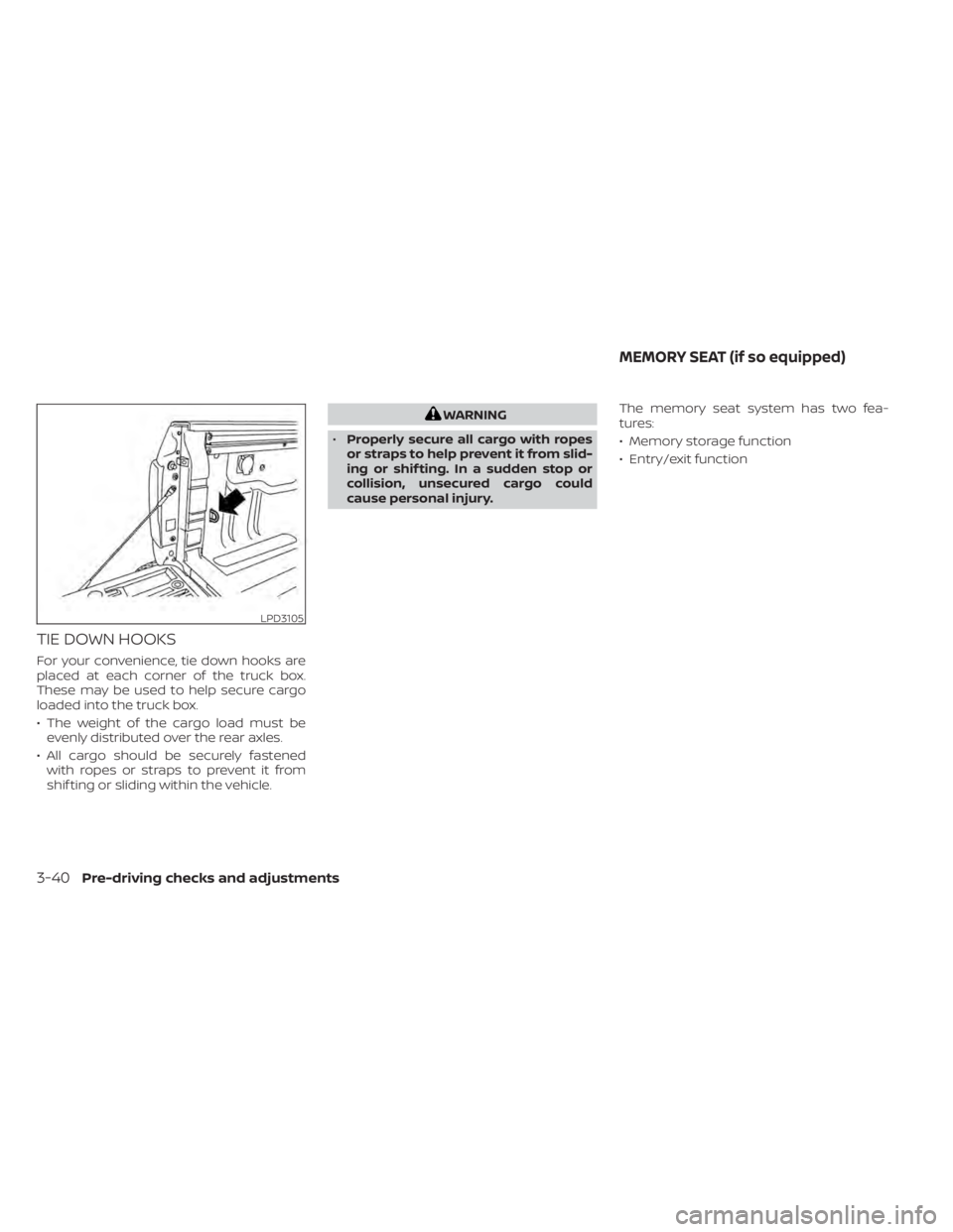
TIE DOWN HOOKS
For your convenience, tie down hooks are
placed at each corner of the truck box.
These may be used to help secure cargo
loaded into the truck box.
• The weight of the cargo load must beevenly distributed over the rear axles.
• All cargo should be securely fastened with ropes or straps to prevent it from
shif ting or sliding within the vehicle.
WARNING
• Properly secure all cargo with ropes
or straps to help prevent it from slid-
ing or shif ting. In a sudden stop or
collision, unsecured cargo could
cause personal injury. The memory seat system has two fea-
tures:
• Memory storage function
• Entry/exit function
LPD3105
MEMORY SEAT (if so equipped)
3-40Pre-driving checks and adjustments
Page 241 of 638

MEMORY STORAGE FUNCTION
Two positions for the driver's seat, steering
column, and outside mirrors (if so
equipped) can be stored in the Memory
Seats. Follow these procedures to set the
memory system.
1. Place the ignition in the ON or ACC posi-tion (the vehicle should be stopped while
setting the memory). 2. Adjust the driver's seat, steering column,
and outside mirrors (if so equipped) to
the desired positions by manually oper-
ating each adjusting switch. For addi-
tional information, see “Seats” (P. 1-2),
“Steering wheel” (P. 3-28) and “Outside
mirrors” (P. 3-32).
3. Push the SET switch and, within 5 sec- onds, push the memory switch (1 or 2).
4. The indicator light for the pushed memory switch will come on and stay
on for approximately 5 seconds.
5. The chime will sound when the memory is stored.NOTE:
If a NEW memory position is stored in the
same memory switch, the previous
memory position will be overwritten by
the new stored position.
Confirming memory storage
• Push the SET switch.
• If a memory position has been stored inthe switch (1 or 2) then the indicator light
for the respective switch will stay on for
approximately 5 seconds.
LINKING A KEY FOB TO A STORED
MEMORY POSITION
Each key fob can be linked to a stored
memory position (memory switch 1 or 2)
with the following procedure.
1. Follow steps 1-3 in the “Memory storage function” section for storing the memory
position.
2. The indicator light for the pushed memory switch will come on. While the
indicator light is on for 5 seconds, press
the
button on the key fob. The haz-
ard lights will flash twice. The indicator
light of the linked memory switch will
blink and click twice. Af ter the indicator
light goes off, the key fob is linked to that
memory setting.
Once it is linked, when the ignition switch is
in the OFF position, pressing the
but-
ton on the key fob will move the driver’s
seat, steering wheel and outside mirrors to
the linked memory switch position.
NOTE:
If a new memory position is stored in the
linked memory switch, then the key fob
will link the new position and overwrites
the previous position.
LPD2302
Pre-driving checks and adjustments3-41
Page 242 of 638
ENTRY/EXIT FUNCTION
This system is designed so that the driver's
seat and steering column will automati-
cally move when the shif t lever is in the P
(Park) position. This allows the driver to
easily get in and out of the driver’s seat.
The driver’s seat will slide backward and
the steering column will move up:
• When the driver’s door is opened with theignition switch in the OFF position.
• When the ignition switch is changed from ACC to OFF with the driver’s door open.
The driver’s seat and steering wheel will
return to the previous position:
• When the ignition switch is changed from ACC or ON while the shif t lever is in the P
(Park) position.
The entry/exit function can be adjusted or
canceled through the vehicle settings in
the vehicle information display by perform-
ing the following:
• Switch the Exit Seat Slide from ON to OFF.
• Switch the Exit Steering UP from ON to OFF.
Restarting the entry/exit function
If the battery cable is disconnected, or if the
fuse opens, the stored memory positions
will be lost and some of the functions will
be restricted:
1. Drive the vehicle over 25 mph (40 km/h).
OR
2. Open and close the driver's door more than two times with the ignition switch
in the OFF position.
The entry/exit function should now work
properly.
SYSTEM OPERATION
The memory seat system will not work or
will stop operating under the following
conditions:
• When the vehicle speed is above 4 mph (7 km/h).
• When any of the memory switches are pushed while the memory seat is operat-
ing.
• When the switch for the driver’s seat and steering column is pushed while the
memory seat is operating.
• When the seat has already been moved to the memorized position. • When no seat position is stored in the
memory switch.
• When the shif t lever is moved from P (Park) to any other position.
The memory seat system can be adjusted
and canceled. It is recommended you visit
a NISSAN dealer for this service.
3-42Pre-driving checks and adjustments
Page 268 of 638
WARNING
• Failure to follow the warnings and in-
structions for proper use of the Mov-
ing Object Detection system could
result in serious injury or death.
• The MOD system is not a substitute
for proper vehicle operation and is
not designed to prevent contact with
objects surrounding the vehicle.
When maneuvering, always use the
outside mirrors and rearview mirror
and turn and check the surroundings
to ensure it is safe to maneuver.
• The system is deactivated at speeds
above 6 mph (10 km/h). It is reacti-
vated at lower speeds.
• The MOD system is not designed to
detect surrounding stationary
objects.
The MOD system can inform the driver of
moving objects near the vehicle when
backing out of garages, maneuvering in
parking lots and in other such instances.
The MOD system detects moving objects
by using image processing technology on
the image shown in the display.MOD SYSTEM OPERATION
The MOD system will turn on automatically
under the following conditions:
• When the shif t lever is in the R (Reverse) position.
• When vehicle speed decreases below ap- proximately 6 mph (10 km/h) and the
camera screen is displayed.
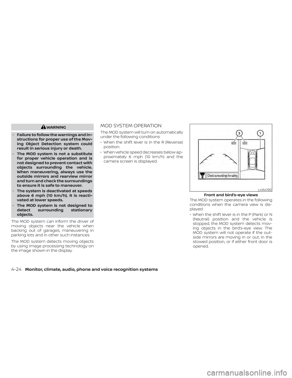
The MOD system operates in the following
conditions when the camera view is dis-
played:
• When the shif t lever is in the P (Park) or N(Neutral) position and the vehicle is
stopped, the MOD system detects mov-
ing objects in the bird’s-eye view. The
MOD system will not operate if the out-
side mirrors are moving in or out, in the
stowed position, or if either front door is
opened.
LHA4190
Front and bird’s-eye views
4-24Monitor, climate, audio, phone and voice recognition systems
Page 301 of 638

DVD PLAYBACK CONTROLS
During video playback, pressto dis-
play the playback controls. Pressorto navigate the controls. Pressto
select the highlighted function or option.
The playback controls will disappear af ter
approximately 5 seconds of no activity. 1.
Context Menu
Press
on the remote to open the
context menu. The menu options will
vary, depending on the source.
2. Progess Bar
Shows elapsed time, total time, and
video progress bar indicator. 3.
Volume
Select to display the volume level indica-
tor. Press
orto increase or
decrease the volume.
4. Night Mode
Select to dim the screen and reduce eye
strain during operation at night.
5. Previous
Select to go to the beginning of the
chapter. Select again to go to the previ-
ous chapter.
6. Rewind
Select to rewind at 2x, 4x, 8x, and 16x
speeds. Select
to resume playback.
7. Stop
Select to stop DVD playback and return
to the menu.
8. Play/Pause
Select once to pause DVD playback. Se-
lect again to resume DVD playback.
9. Fast Forward
Select to fast forward at 2x, 4x, 8x, and 16x
speeds. Select
to resume playback.
10. Next
Select to go to the next chapter.
LHA4888
Monitor, climate, audio, phone and voice recognition systems4-57