2021 NISSAN TITAN steering wheel
[x] Cancel search: steering wheelPage 201 of 638

3 Pre-driving checks and adjustments
Keys.............................................3-2NISSAN Intelligent Key® .......................3-2
NISSAN Vehicle Immobilizer System
keys..........................................3-4
Doors ...........................................3-4
Locking with key .............................3-5
Locking with inside lock knob ................3-6
Locking with power door lock switch .........3-6
Rear doors (King Cab® models) ............... 3-7
Automatic door locks (if so equipped) ........3-8
Child safety rear door lock
(if so equipped) ...............................3-9
NISSAN Intelligent Key® system ..................3-9
Operating range ............................. 3-11
Door locks/unlocks precaution ...............3-11
NISSAN Intelligent Key® Operation ...........3-12
How to use the remote keyless entry
function ..................................... 3-15
Warning signals ............................. 3-19
Troubleshooting guide ......................3-20
Remote Engine Start (if so equipped) ...........3-22
Remote Engine Start operating range .......3-22
Remote starting the vehicle .................3-23
Extending engine run time ..................3-23
Canceling a Remote Engine Start ...........3-23
Conditions the Remote Engine Start will
notwork .................................... 3-24Hood
........................................... 3-25
Fuel-filler door .................................. 3-25
Gasoline fuel engines .......................3-26
Steering wheel ................................. 3-28
Manual operation (if so equipped) ...........3-28
Automatic operation (if so equipped) ........3-29
Sun visors ...................................... 3-30
Vanity mirrors (if so equipped) ...............3-30
Card holder (driver’s side only) ...............3-31
Mirrors ......................................... 3-31
Manual anti-glare rearview mirror
(if so equipped) .............................. 3-31
Automatic anti-glare rearview mirror
(if so equipped) .............................. 3-31
Outside mirrors ............................. 3-32
Truck box ...................................... 3-36
Tailgate ..................................... 3-36
Tie down hooks ............................. 3-40
Memor
y Seat (if so equipped) ..................3-40
Memory storage function ...................3-41
Linking a key fob to a stored memory
position ..................................... 3-41
Entry/exit function .......................... 3-42
System operation ........................... 3-42
Page 228 of 638

Loose Fuel Cap warning
The Loose Fuel Cap warning appears in the
vehicle information display when the fuel-
filler cap is not tightened correctly af ter the
vehicle has been refueled. It may take a few
driving trips for the message to be dis-
played. To turn off the warning, perform the
following:
1.
Remove and install the fuel-filler cap as
previously described as soon as possible.
2. Tighten the fuel-filler cap until a single click is heard.
WARNING
• Do not adjust the steering wheel
while driving. You could lose control
of your vehicle and cause an
accident.
• Do not adjust the steering wheel any
closer to you than is necessary for
proper steering operation and com-
fort. The driver's air bag inflates with
great force. If you are unrestrained,
leaning forward, sitting sideways or
out of position in any way, you are at
greater risk of injury or death in a
crash. You may also receive serious
or fatal injuries from the air bag if you
are up against it when it inflates. Al-
ways sit back against the seatback
and as far away as practical from the
steering wheel. Always use the seat
belts.
MANUAL OPERATION (if so
equipped)
Tilt and telescopic operation
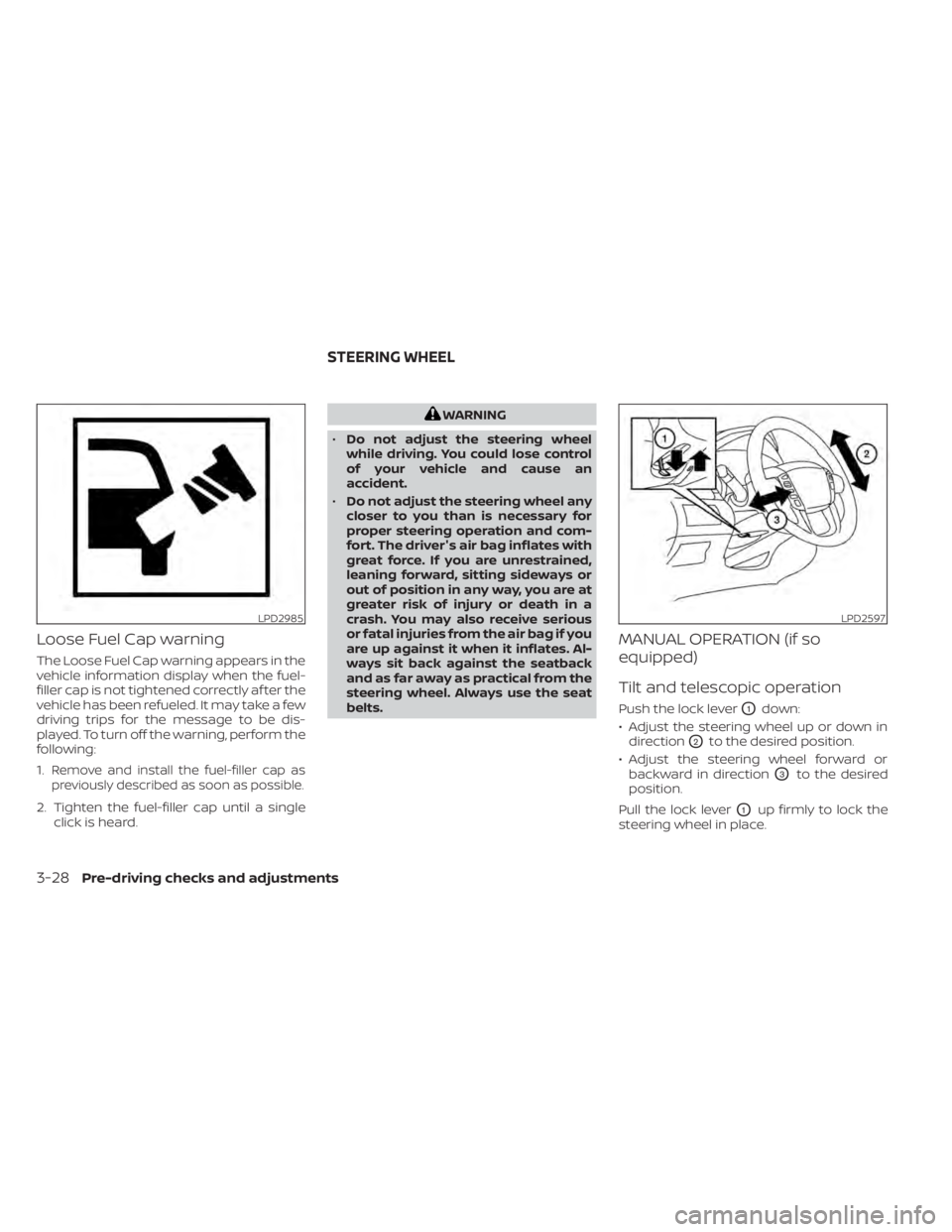
Push the lock leverO1down:
• Adjust the steering wheel up or down in direction
O2to the desired position.
• Adjust the steering wheel forward or backward in direction
O3to the desired
position.
Pull the lock lever
O1up firmly to lock the
steering wheel in place.
LPD2985LPD2597
STEERING WHEEL
3-28Pre-driving checks and adjustments
Page 229 of 638

AUTOMATIC OPERATION (if so
equipped)
Tilt and telescopic operation
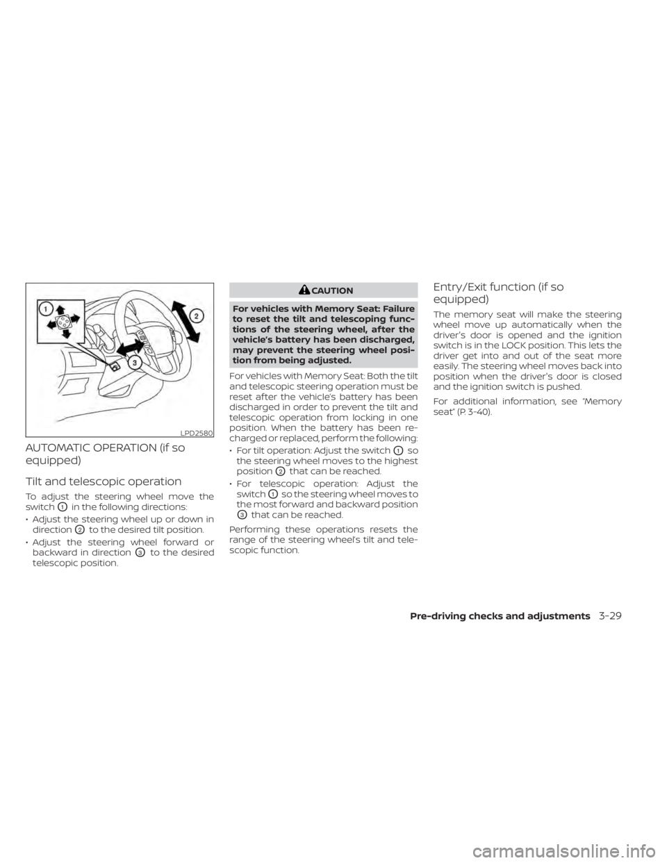
To adjust the steering wheel move the
switch
O1in the following directions:
• Adjust the steering wheel up or down in direction
O2to the desired tilt position.
• Adjust the steering wheel forward or backward in direction
O3to the desired
telescopic position.
CAUTION
For vehicles with Memory Seat: Failure
to reset the tilt and telescoping func-
tions of the steering wheel, af ter the
vehicle’s battery has been discharged,
may prevent the steering wheel posi-
tion from being adjusted.
For vehicles with Memory Seat: Both the tilt
and telescopic steering operation must be
reset af ter the vehicle’s battery has been
discharged in order to prevent the tilt and
telescopic operation from locking in one
position. When the battery has been re-
charged or replaced, perform the following:
• For tilt operation: Adjust the switch
O1so
the steering wheel moves to the highest
position
O2that can be reached.
• For telescopic operation: Adjust the switch
O1so the steering wheel moves to
the most forward and backward position
O3that can be reached.
Performing these operations resets the
range of the steering wheel’s tilt and tele-
scopic function.
Entry/Exit function (if so
equipped)
The memory seat will make the steering
wheel move up automatically when the
driver's door is opened and the ignition
switch is in the LOCK position. This lets the
driver get into and out of the seat more
easily. The steering wheel moves back into
position when the driver's door is closed
and the ignition switch is pushed.
For additional information, see “Memory
seat” (P. 3-40).
LPD2580
Pre-driving checks and adjustments3-29
Page 241 of 638

MEMORY STORAGE FUNCTION
Two positions for the driver's seat, steering
column, and outside mirrors (if so
equipped) can be stored in the Memory
Seats. Follow these procedures to set the
memory system.
1. Place the ignition in the ON or ACC posi-tion (the vehicle should be stopped while
setting the memory). 2. Adjust the driver's seat, steering column,
and outside mirrors (if so equipped) to
the desired positions by manually oper-
ating each adjusting switch. For addi-
tional information, see “Seats” (P. 1-2),
“Steering wheel” (P. 3-28) and “Outside
mirrors” (P. 3-32).
3. Push the SET switch and, within 5 sec- onds, push the memory switch (1 or 2).
4. The indicator light for the pushed memory switch will come on and stay
on for approximately 5 seconds.
5. The chime will sound when the memory is stored.NOTE:
If a NEW memory position is stored in the
same memory switch, the previous
memory position will be overwritten by
the new stored position.
Confirming memory storage
• Push the SET switch.
• If a memory position has been stored inthe switch (1 or 2) then the indicator light
for the respective switch will stay on for
approximately 5 seconds.
LINKING A KEY FOB TO A STORED
MEMORY POSITION
Each key fob can be linked to a stored
memory position (memory switch 1 or 2)
with the following procedure.
1. Follow steps 1-3 in the “Memory storage function” section for storing the memory
position.
2. The indicator light for the pushed memory switch will come on. While the
indicator light is on for 5 seconds, press
the
button on the key fob. The haz-
ard lights will flash twice. The indicator
light of the linked memory switch will
blink and click twice. Af ter the indicator
light goes off, the key fob is linked to that
memory setting.
Once it is linked, when the ignition switch is
in the OFF position, pressing the
but-
ton on the key fob will move the driver’s
seat, steering wheel and outside mirrors to
the linked memory switch position.
NOTE:
If a new memory position is stored in the
linked memory switch, then the key fob
will link the new position and overwrites
the previous position.
LPD2302
Pre-driving checks and adjustments3-41
Page 242 of 638

ENTRY/EXIT FUNCTION
This system is designed so that the driver's
seat and steering column will automati-
cally move when the shif t lever is in the P
(Park) position. This allows the driver to
easily get in and out of the driver’s seat.
The driver’s seat will slide backward and
the steering column will move up:
• When the driver’s door is opened with theignition switch in the OFF position.
• When the ignition switch is changed from ACC to OFF with the driver’s door open.
The driver’s seat and steering wheel will
return to the previous position:
• When the ignition switch is changed from ACC or ON while the shif t lever is in the P
(Park) position.
The entry/exit function can be adjusted or
canceled through the vehicle settings in
the vehicle information display by perform-
ing the following:
• Switch the Exit Seat Slide from ON to OFF.
• Switch the Exit Steering UP from ON to OFF.
Restarting the entry/exit function
If the battery cable is disconnected, or if the
fuse opens, the stored memory positions
will be lost and some of the functions will
be restricted:
1. Drive the vehicle over 25 mph (40 km/h).
OR
2. Open and close the driver's door more than two times with the ignition switch
in the OFF position.
The entry/exit function should now work
properly.
SYSTEM OPERATION
The memory seat system will not work or
will stop operating under the following
conditions:
• When the vehicle speed is above 4 mph (7 km/h).
• When any of the memory switches are pushed while the memory seat is operat-
ing.
• When the switch for the driver’s seat and steering column is pushed while the
memory seat is operating.
• When the seat has already been moved to the memorized position. • When no seat position is stored in the
memory switch.
• When the shif t lever is moved from P (Park) to any other position.
The memory seat system can be adjusted
and canceled. It is recommended you visit
a NISSAN dealer for this service.
3-42Pre-driving checks and adjustments
Page 249 of 638

Vehicle width guide linesO4
Indicate the vehicle width when backing
up.
Predicted course lines
O5
Indicate the predicted course when back-
ing up. The predicted course lines will be
displayed on the monitor when the shif t
lever is in the R (Reverse) position and the
steering wheel is turned. The predicted
course lines will move depending on how
much the steering wheel is turned and will
not be displayed while the steering wheel is
in the straight-ahead position.
The vehicle width guide lines and the width
of the predicted course lines are wider than
the actual width and course.
Center guide lines
O6
Indicates the vehicle’s center.
DIFFERENCE BETWEEN PREDICTED
AND ACTUAL DISTANCES
The displayed guidelines and their loca-
tions on the ground are for approximate
reference only. Objects on uphill or downhill
surfaces or projecting objects will be actu-
ally located at distances different from
those displayed in the monitor relative to
the guidelines (refer to illustrations). When
in doubt, turn around and view the objects
as you are backing up, or park and exit the
vehicle to view the positioning of objects
behind the vehicle.
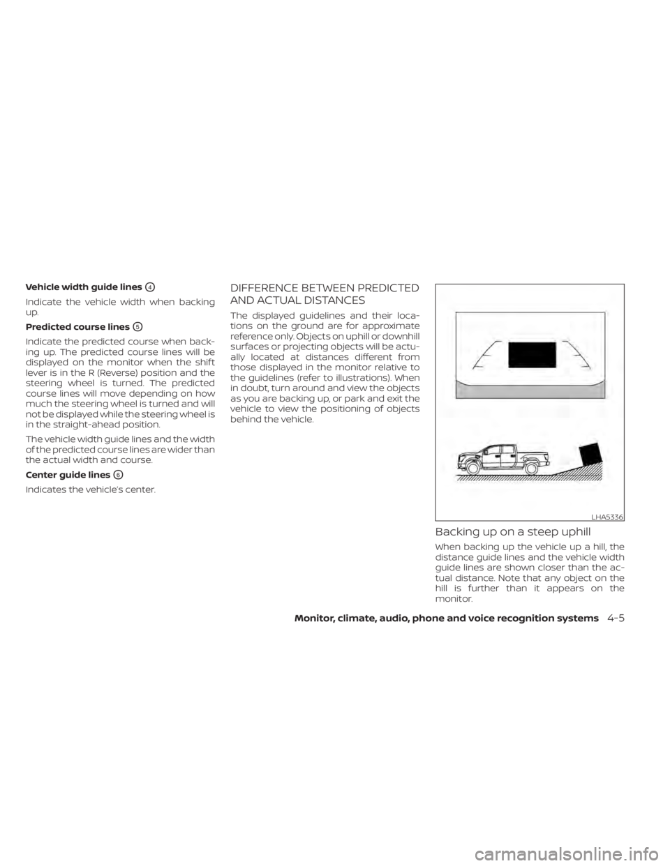
Backing up on a steep uphill
When backing up the vehicle up a hill, the
distance guide lines and the vehicle width
guide lines are shown closer than the ac-
tual distance. Note that any object on the
hill is further than it appears on the
monitor.
LHA5336
Monitor, climate, audio, phone and voice recognition systems4-5
Page 251 of 638

object when backing up to the positionOA
if the object projects over the actual back-
ing up course.
HOW TO PARK WITH PREDICTED
COURSE LINES
WARNING
• If the tires are replaced with different
sized tires, the predicted course lines
may be displayed incorrectly.
• On a snow-covered or slippery road,
there may be a difference between
the predicted course line and the ac-
tual course line.
• If the battery is disconnected or be-
comes discharged, the predicted
course lines may be displayed incor-
rectly. If this occurs, please perform
the following procedures:
– Turn the steering wheel from lock
to lock while the engine is
running.
– Drive the vehicle on a straight road
for more than 5 minutes.
• When the steering wheel is turned
with the ignition switch in the ACC
position, the predicted course lines
may be displayed incorrectly. 1. Visually check that the parking space is
safe before parking your vehicle.
2. The rear view of the vehicle is displayed on the screen
OAwhen the shif t lever is
moved to the R (Reverse) position. 3. Slowly back up the vehicle adjusting the
steering wheel so that the predicted
course lines
OBenter the parking space
OC.
LHA5340LHA5341
Monitor, climate, audio, phone and voice recognition systems4-7
Page 252 of 638

4. Maneuver the steering wheel to makethe vehicle width guide lines
ODparallel
to the parking space
OCwhile referring
to the predicted course lines.
5. When the vehicle is parked in the space completely, move the shif t lever to the P
(Park) position and apply the parking
brake.
ADJUSTING THE SCREEN
1. Press the CAMERA button.
2. Touch the “Display Settings” key.
3. Touch the “Brightness”, “Contrast”, Tint”,“Color”, or “Black Level” key.
4. Adjust the item by touching the “+” or “–” key on the touch-screen display.
NOTE:
Do not adjust any of the display settings
of the RearView Monitor while the ve-
hicle is moving.
HOW TO TURN ON AND OFF
PREDICTED COURSE LINES
To toggle ON and OFF the predicted course
lines while in the P (Park) position:
1. Press the CAMERA button.
2. Touch the “Predicted Course Lines” keyto turn the feature ON or OFF.
To toggle ON and OFF the predicted course
lines or center guide line while in the R (Re-
verse) position, press the CAMERA button.
REARVIEW MONITOR SYSTEM
LIMITATIONS
WARNING
Listed below are the system limitations
for RearView Monitor. Failure to oper-
ate the vehicle in accordance with
these system limitations could result in
serious injury or death.
• The system cannot completely elimi-
nate blind spots and may not show
every object.
LHA3522
4-8Monitor, climate, audio, phone and voice recognition systems