2021 NISSAN TITAN stop
[x] Cancel search: stopPage 591 of 638

5. Determine the combined weightof luggage and cargo being
loaded on the vehicle. That weight
may not safely exceed the avail-
able cargo and luggage load ca-
pacity calculated in step 4.
6. If your vehicle will be towing a trailer, load from your trailer will be
transferred to your vehicle. Con-
sult this manual to determine
how this reduces the available
cargo and luggage load capacity
of your vehicle.
Before driving a loaded vehicle, con-
firm that you do not exceed the
GVWR or the GAWR for your vehicle.
For additional information, see “Mea-
surement of weights” (P. 10-33).
Also check tires for proper inflation
pressures. For additional informa-
tion, see “Tire and Loading Informa-
tion label” (P. 8-37).
SECURING THE LOAD
For your convenience, tie down hooks are
placed at each corner of the truck box.
These may be used to help secure cargo
loaded into the truck box.
WARNING
• Properly secure all cargo with ropes
or straps to help prevent it from slid-
ing or shif ting. Do not place cargo
higher than the seatbacks. In a sud-
den stop or collision, unsecured
cargo could cause personal injury.
• Do not load your vehicle any heavier
than the GVWR or the maximum front
and rear GAWRs. If you do, parts of
your vehicle can break, tire damage
could occur, or it can change the way
your vehicle handles. This could re-
sult in loss of control and cause per-
sonal injury.
LTI2481
Technical and consumer information10-25
Page 592 of 638
UTILI-TRACK® CHANNEL SYSTEM
(if so equipped)
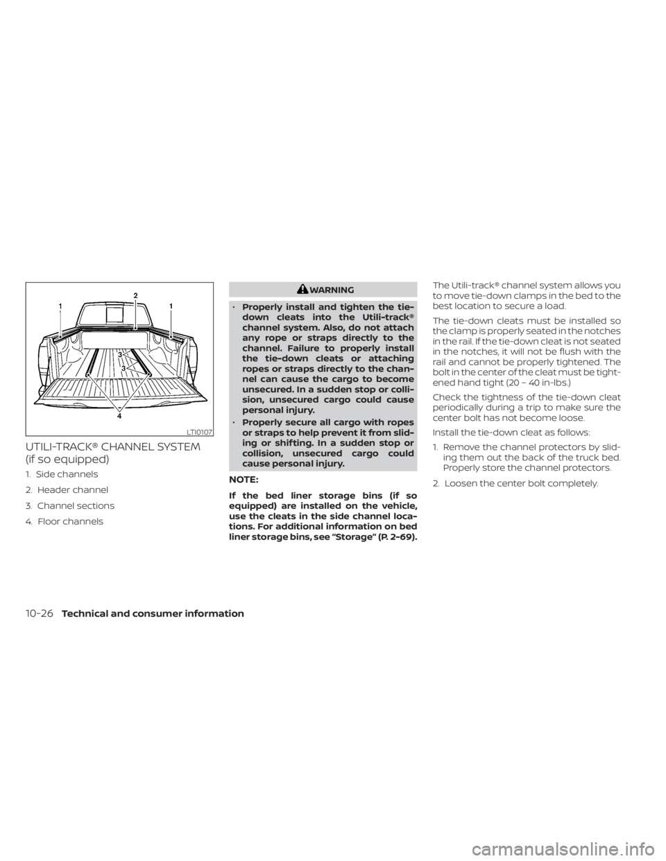
1. Side channels
2. Header channel
3. Channel sections
4. Floor channels
WARNING
• Properly install and tighten the tie-
down cleats into the Utili-track®
channel system. Also, do not attach
any rope or straps directly to the
channel. Failure to properly install
the tie-down cleats or attaching
ropes or straps directly to the chan-
nel can cause the cargo to become
unsecured. In a sudden stop or colli-
sion, unsecured cargo could cause
personal injury.
• Properly secure all cargo with ropes
or straps to help prevent it from slid-
ing or shif ting. In a sudden stop or
collision, unsecured cargo could
cause personal injury.
NOTE:
If the bed liner storage bins (if so
equipped) are installed on the vehicle,
use the cleats in the side channel loca-
tions. For additional information on bed
liner storage bins, see “Storage” (P. 2-69). The Utili-track® channel system allows you
to move tie-down clamps in the bed to the
best location to secure a load.
The tie-down cleats must be installed so
the clamp is properly seated in the notches
in the rail. If the tie-down cleat is not seated
in the notches, it will not be flush with the
rail and cannot be properly tightened. The
bolt in the center of the cleat must be tight-
ened hand tight (20 – 40 in-lbs.)
Check the tightness of the tie-down cleat
periodically during a trip to make sure the
center bolt has not become loose.
Install the tie-down cleat as follows:
1. Remove the channel protectors by slid-
ing them out the back of the truck bed.
Properly store the channel protectors.
2. Loosen the center bolt completely.
LTI0107
10-26Technical and consumer information
Page 597 of 638

LOADING TIPS
• The GVW must not exceed GVWR orGAWR as specified on the F.M.V.S.S./
C.M.V.S.S. certification label.
• Do not load the front and rear axle to the GAWR. Doing so will exceed
the GVWR.
WARNING
• Properly secure all cargo with
ropes or straps to help prevent
it from sliding or shif ting. Do
not place cargo higher than the
seatbacks. In a sudden stop or
collision, unsecured cargo
could cause personal injury. •
Do not load your vehicle any
heavier than the GVWR or the
maximum front and rear
GAWRs. If you do, parts of your
vehicle can break, tire damage
could occur, or it can change
the way your vehicle handles.
This could result in loss of con-
trol and cause personal injury.
• Overloading not only can
shorten the life of your vehicle
and the tire, but can also cause
unsafe vehicle handling and
longer braking distances. This
may cause a premature tire
failure which could result in a
serious accident and personal
injury. Failures caused by over-
loading are not covered by the
vehicle’s warranty.
CREW CAB MODELS
Crew Cab short wheel base models
should not be used to carry a slide-in
camper.
KING CAB® MODELS
This information is provided for you to
properly install a slide-in camper and is
based on the National Highway Traffic
Safety Administration regulations. It is rec-
ommended that, before installing the
camper, you carefully read the following in-
formation and ensure that the camper
meets the specifications.
This information may not apply to some
Canada model vehicles.
SPECIAL BODY VEHICLES
Some vehicles are equipped with commer-
cial or camper bodies. However, this Own-
er's Manual does not cover these options.
For additional information, refer to the
body manufacturer's instruction manual.
TRUCK-CAMPER LOADING
INFORMATION
Technical and consumer information10-31
Page 602 of 638
Towing with Weight Distributing Class 4
Hitch
The Class 4 towing capacities shown in the
towing load specification charts are calcu-
lated per the SAE J2807 standards. Addi-
tional passengers, cargo and/or optional
equipment, such as the trailer hitch, will
add weight to the vehicle and reduce your
vehicle's maximum towing capacity and
trailer tongue load.
The vehicle and trailer need to be weighed
to confirm the vehicle is within the GVWR,
Front GAWR, Rear GAWR, Gross Combined
Weight Rating (GCWR) and Towing capacity.
All vehicle and trailer weights can be mea-
sured using platform type scales com-
monly found at truck stops, highway weigh
stations, building supply centers or salvage
yards.
Towing with Gooseneck Hitch
The gooseneck towing capacities are cal-
culated assuming a base vehicle with
driver and any options required to achieve
the rating. Additional passengers, cargo
and/or optional equipment, such as the
trailer hitch, will add weight to the vehicle
and reduce your vehicle's maximum tow-
ing capacity and trailer tongue load.The vehicle and trailer need to be weighed
to confirm the vehicle is within the GVWR,
Front GAWR, Rear GAWR, Gross Combined
Weight Rating (GCWR) and Towing capacity.
All vehicle and trailer weights can be mea-
sured using platform type scales com-
monly found at truck stops, highway weigh
stations, building supply centers or salvage
yards.
To determine the available payload capac-
ity for tongue/king pin load, use the follow-
ing procedure.
1. Locate the GVWR on the F.M.V.S.S./
C.M.V.S.S. certification label.
2. Weigh your vehicle on the scale with all of the passengers and cargo that are
normally in the vehicle when towing a
trailer.
3. Subtract the actual vehicle weight from the GVWR. The remaining amount is the
available maximum tongue/king pin
load.
To determine the available towing capacity,
use the following procedure.
1. Find the GCWR for your vehicle on the "Towing load/specification" chart found
in this section. 2. Subtract the actual vehicle weight from
the GCWR. The remaining amount is the
available maximum towing capacity.
To determine the Gross Trailer Weight,
weigh your trailer on a scale with all equip-
ment and cargo, that are normally in the
trailer when it is towed. Make sure the
Gross trailer weight is not more than the
Gross Trailer Weight Rating shown on the
trailer and is not more than the calculated
available maximum towing capacity.
Also weigh the front and rear axles on the
scale to make sure the Front Gross Axle
Weight and Rear Gross Axle Weight are not
more than Front Gross Axle Weight and
Rear Gross Axle Weight on the F.M.V.S.S./
C.M.V.S.S. certification label. The cargo in
the trailer and vehicle may need to be
moved or removed to meet the specified
ratings.
Example:
• Gross Vehicle Weight (GVW) as weighed on a scale - including passengers, cargo
and hitch - 7,804 lbs. (3,540 kg).
• Gross Vehicle Weight Rating (GVWR) from F.M.V.S.S./C.M.V.S.S. certification label -
8,990 lbs. (4,078 kg).
10-36Technical and consumer information
Page 608 of 638
should install these hitches as it is very im-
portant to mount the hitch correctly to dis-
tribute the king pin weight for the proper
load carrying and sway control perfor-
mance.
The king pin weight should be 15% of the
fully loaded trailer. Make sure the king pin
weight does not cause the gross vehicle
weight to exceed the Gross Maximum
Weight Rating or the rear axle weight to
exceed the Rear Gross Axle Weight rating.
For additional information, see “Maximum
load limits” (P. 10-34).
The weight of the trailer should not exceed
the maximum towing capacity for the ve-
hicle. For additional information, see “Tow-
ing load/specification” chart (P. 10-37).
Make sure the trailer design allows for the
correct vehicle to trailer clearances before
purchasing a 5th wheel trailer.WARNING
• The hitch should not be attached to
or affect the operation of the impact-
absorbing bumper.
• Do not use axle-mounted hitches.
• Do not modif y the vehicle exhaust
system, brake system, etc. to install a
trailer hitch.
• To reduce the possibility of addi-
tional damage if your vehicle is
struck from the rear, where practical,
remove the receiver when not in use.
• Regularly check that all trailer hitch
mounting bolts are securely
mounted.
• When towing with the hitch ball
mounted to the rear bumper, do not
make sharp turns. The trailer may
contact the bumper and cause dam-
age to the bumper or trailer.
• When towing a 5th wheel trailer, do
not make sharp turns while driving or
backing. The trailer may contact the
vehicle and cause damage to both
the trailer and vehicle.
CAUTION
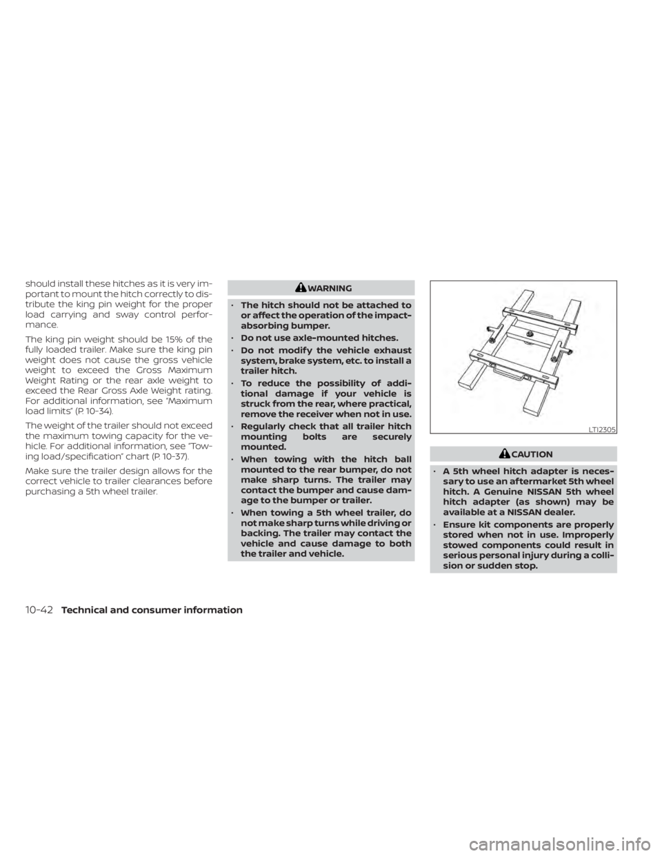
• A 5th wheel hitch adapter is neces-
sary to use an af termarket 5th wheel
hitch. A Genuine NISSAN 5th wheel
hitch adapter (as shown) may be
available at a NISSAN dealer.
• Ensure kit components are properly
stored when not in use. Improperly
stowed components could result in
serious personal injury during a colli-
sion or sudden stop.
LTI2305
10-42Technical and consumer information
Page 612 of 638

Trailer lights
CAUTION
When splicing into the vehicle electrical
system, a commercially available
power-type module/converter must
be used to provide power for all trailer
lighting. This unit uses the vehicle bat-
tery as a direct power source for all
trailer lights while using the vehicle tail
light, stop light and turn signal circuits
as a signal source. The module/
converter must draw no more than 15
milliamps from the stop and tail lamp
circuits. Using a module/converter that
exceeds these power requirements
may damage the vehicle's electrical
system. See a reputable trailer retailer
to obtain the proper equipment and to
have it installed.
Trailer lights should comply with federal
and/or local regulations. For assistance in
hooking up trailer lights, it is recommended
that you contact a NISSAN dealer or repu-
table trailer retailer. Vehicles equipped with
the optional trailer tow package are
equipped with a 7-pin trailer harness con-
nector. If your trailer is equipped with a flat
4-pin connector, an adapter will be needed
to connect the trailer lights to the vehicle. Adapters are available at auto parts stores
and hitch retailers.Trailer brakes (if so equipped)
If your trailer is equipped with a braking
system, make sure it conforms to federal
and/or local regulations and that it is prop-
erly installed.
Vehicles equipped with a 7–pin trailer har-
ness connector are pre-wired for a trailer
brake controller. It is recommended that
you visit a NISSAN dealer for a trailer brake
adapter harness.
When towing a trailer load of 3,500 lbs.
(1587 kg) or more, trailers with a brake
system MUST be used.
However, most
states require a separate braking system
on trailers with a loaded weight above a
specific amount. Make sure the trailer
meets the local regulations and the regu-
lations where you plan to tow.
WARNING
The Gross Combined Weight Rating
(GCWR) must never exceed the vehicle
manufacturers recommendation.
Several types of braking systems are avail-
able. Surge Brakes -
The surge brake actuator is
mounted on the trailer tongue with a hy-
draulic line running to each trailer wheel.
Surge brakes are activated by the trailer
pushing against the hitch ball when the
tow vehicle is braking. Hydraulic surge
brakes are common on rental trailers and
some boat trailers. In this type of system,
there is no hydraulic or electric connection
for brake operation between the tow ve-
hicle and the trailer.
CAUTION
Your factory trailer brake control unit
will not activate surge-style trailer
brakes
Electric Trailer Brakes - Electric braking
systems are activated by an electronic sig-
nal sent from a trailer brake controller (spe-
cial brake-sensing module). If electric trailer
brakes are used, see “Electric trailer brake
controller" (P. 10-49).
Have a professional supplier of towing
equipment make sure the trailer brakes are
properly installed and demonstrate proper
brake function testing.
10-46Technical and consumer information
Page 614 of 638
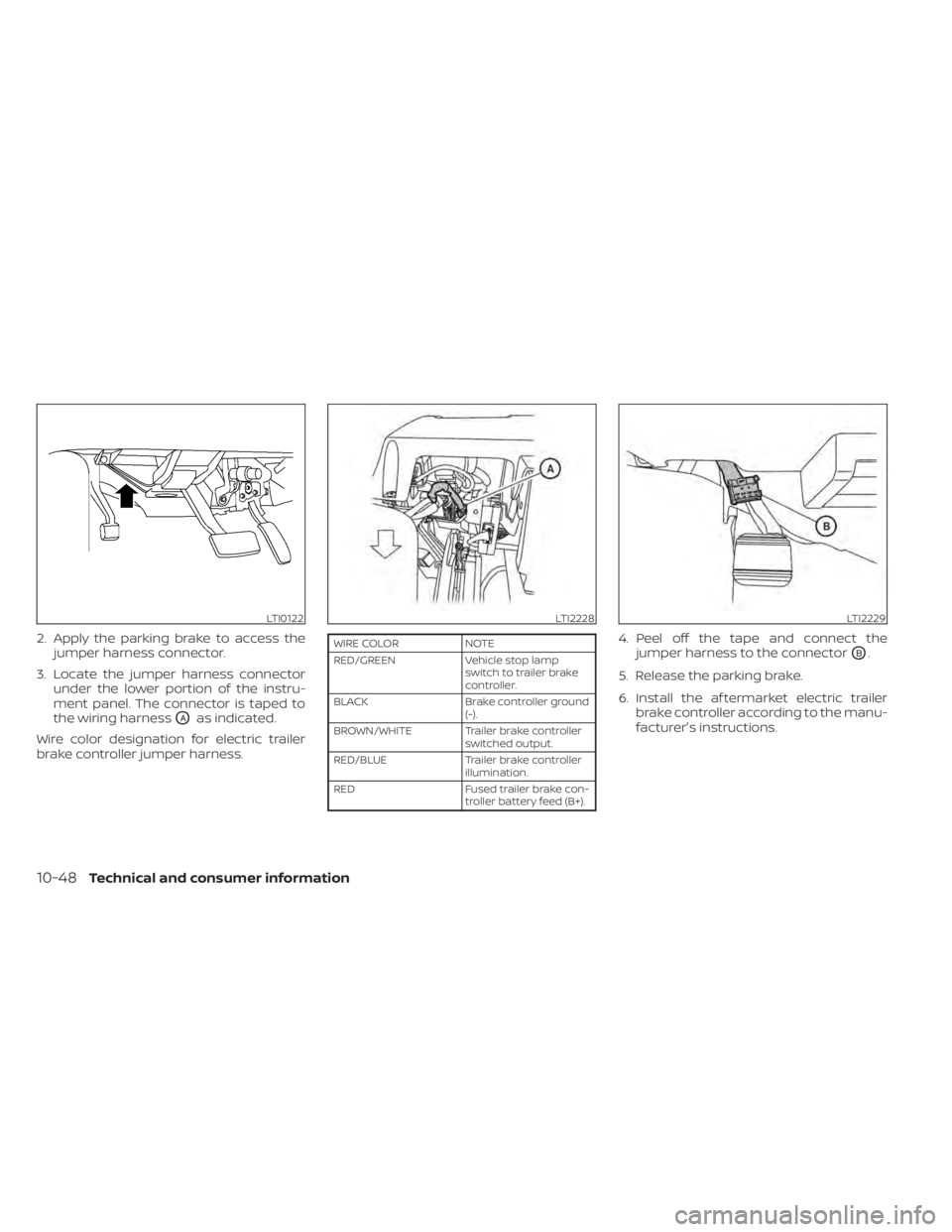
2. Apply the parking brake to access thejumper harness connector.
3. Locate the jumper harness connector under the lower portion of the instru-
ment panel. The connector is taped to
the wiring harness
OAas indicated.
Wire color designation for electric trailer
brake controller jumper harness.
WIRE COLOR NOTE
RED/GREEN Vehicle stop lamp
switch to trailer brake
controller.
BLACK Brake controller ground
(-).
BROWN/WHITE Trailer brake controller switched output.
RED/BLUE Trailer brake controller
illumination.
RED Fused trailer brake con-
troller battery feed (B+).4. Peel off the tape and connect the jumper harness to the connector
OB.
5. Release the parking brake.
6. Install the af termarket electric trailer brake controller according to the manu-
facturer's instructions.
LTI0122LTI2228LTI2229
10-48Technical and consumer information
Page 618 of 638

• Be certain your rearview mirrors conformto all federal, state or local regulations. If
not, install any mirrors required for towing
before driving the vehicle.
• Determine the overall height of the ve- hicle and trailer so the required clearance
is known.
Trailer towing tips
In order to gain skill and an understanding
of the vehicle's behavior, you should prac-
tice turning, stopping and backing up in
an area which is free from traffic. Steering
stability and braking performance will be
somewhat different than under normal
driving conditions.
• Always secure items in the trailer to pre-vent load shif t while driving.
• Lock the trailer hitch coupler with a pin or lock to prevent the coupler from inadver-
tently becoming unlatched.
• Avoid abrupt starts, acceleration or stops.
• Avoid sharp turns or lane changes.
• Always drive your vehicle at a moderate speed. • When backing up, hold the bottom of the
steering wheel with one hand. Move your
hand in the direction in which you want
the trailer to go. Make small corrections
and back up slowly. If possible, have
someone guide you when you are back-
ing up.
Always block the wheels on both vehicle
and trailer when parking. Parking on a
slope is not recommended; however, if you
must do so:
CAUTION
If you move the shif t selector to the P
(Park) position before blocking the
wheels and applying the parking brake,
transmission damage could occur.
1. Apply and hold the brake pedal.
2. Have someone place blocks on the downhill side of the vehicle and trailer
wheels.
3. Af ter the wheel blocks are in place, slowly release the brake pedal until the
blocks absorb the vehicle load.
4. Apply the parking brake.
5. Shif t the transmission into P (Park). 6. Make sure the
indicator light (if so
equipped) indicates the transfer case is
in 4H, 4LO, or 2H and that the ATP light is
off. If the
indicator light is flashing,
or the ATP light is ON, make sure the
transmission is in P (Park) (A/T) and turn
the 4WD switch to 2WD or 4H. For addi-
tional information, see “Automatic
transmission park warning light” (P. 2-13)
and “Using 4-wheel drive (4WD)” (P. 5-105).
7. Turn off the engine.
To drive away:
1. Start the vehicle.
2. Apply and hold the brake pedal.
3. Shif t the transmission into gear.
4. Release the parking brake.
5. Drive slowly until the vehicle and trailer are clear from the blocks.
6. Apply and hold the brake pedal.
7. Have someone retrieve and store the blocks.
10-52Technical and consumer information