Page 200 of 528

NOTE:
Do not hang any objects over the sen-
sors
O1or apply glass cleaner to the sen-
sors. Doing so will reduce the sensitivity
of the sensors, resulting in improper
operation.
The indicator light
O3will illuminate when
the automatic anti-glare feature is operat-
ing.
Type B (if so equipped)
• To turn off the anti-glare feature, press the O button and the indicator light will
turn off. • To turn on the anti-glare feature, press
the | button and the indicator light will
turn on.
For additional information on HomeLink®
Universal Transceiver operation, refer to
“HomeLink® Universal Transceiver” in the
“Instruments and controls” section of this
manual.
OUTSIDE MIRRORS
The outside mirror remote control will op-
erate only when the ignition switch is in the
ON position.
Move the small switch
O1to select the right
or lef t mirror. Adjust each mirror to the de-
sired position using the large switch
O2.
Move the switch to the center (neutral) po-
sition to prevent accidentally moving the
mirror.
LPD2411
Type B (if so equipped)
3-30Pre-driving checks and adjustments
Page 201 of 528
WARNING
• Objects viewed in the outside mirror
on the passenger side are closer than
they appear. Be careful when moving
to the right. Using only this mirror
could cause an accident. Use the in-
side mirror or glance over your
shoulder to properly judge distances
to other objects.
• Do not adjust the mirrors while driv-
ing. You could lose control of your ve-
hicle and cause an accident.
Manual folding outside mirrors
Pull the outside mirror toward the door to
fold it.
Heated mirrors (if so equipped)
Some outside mirrors can be heated to
defrost or de-ice for improved visibility. For
additional information, refer to “Rear win-
dow and outside mirror (if so equipped)
defroster switch” in the “Instruments and
controls” section of this manual.
LPD2112
Page 219 of 528

WARNING
Failure to follow the warnings and in-
structions for the proper use of the In-
telligent Around View Monitor system
could result in serious injury or death
• The Intelligent Around View Monitor
is a convenience feature and is not a
substitute for proper vehicle opera-
tion because it has areas where ob-
jects cannot be viewed. The four cor-
ners of the vehicle in particular, are
areas where objects do not always
appear in the bird’s-eye, front, or rear
views. Always check your surround-
ings to be sure that it is safe to move
before operating the vehicle. Always
operate the vehicle slowly.
• The driver is always responsible for
safety during parking and other
maneuvers.
CAUTION
Do not scratch the camera lens when
cleaning dirt or snow from the front of
the camera. The Intelligent Around View Monitor sys-
tem is designed as an aid to the driver in
situations such as slot parking or parallel
parking.
The monitor displays various views of the
position of the vehicle in a split screen for-
mat. Not all views are available at all times.
Available views:
• Front View
An approximately 150–degree view of the
front of the vehicle.
• Rear View An approximately 150–degree view of the
rear of the vehicle.
• Bird's-Eye View The surrounding views of the vehicle
from above.
• Front-Side View The view around and ahead of the front
passenger's side wheel.
• Full Screen Rear View (if so equipped) The view to the rear of the vehicle (which
is a little wider than the standard Rear
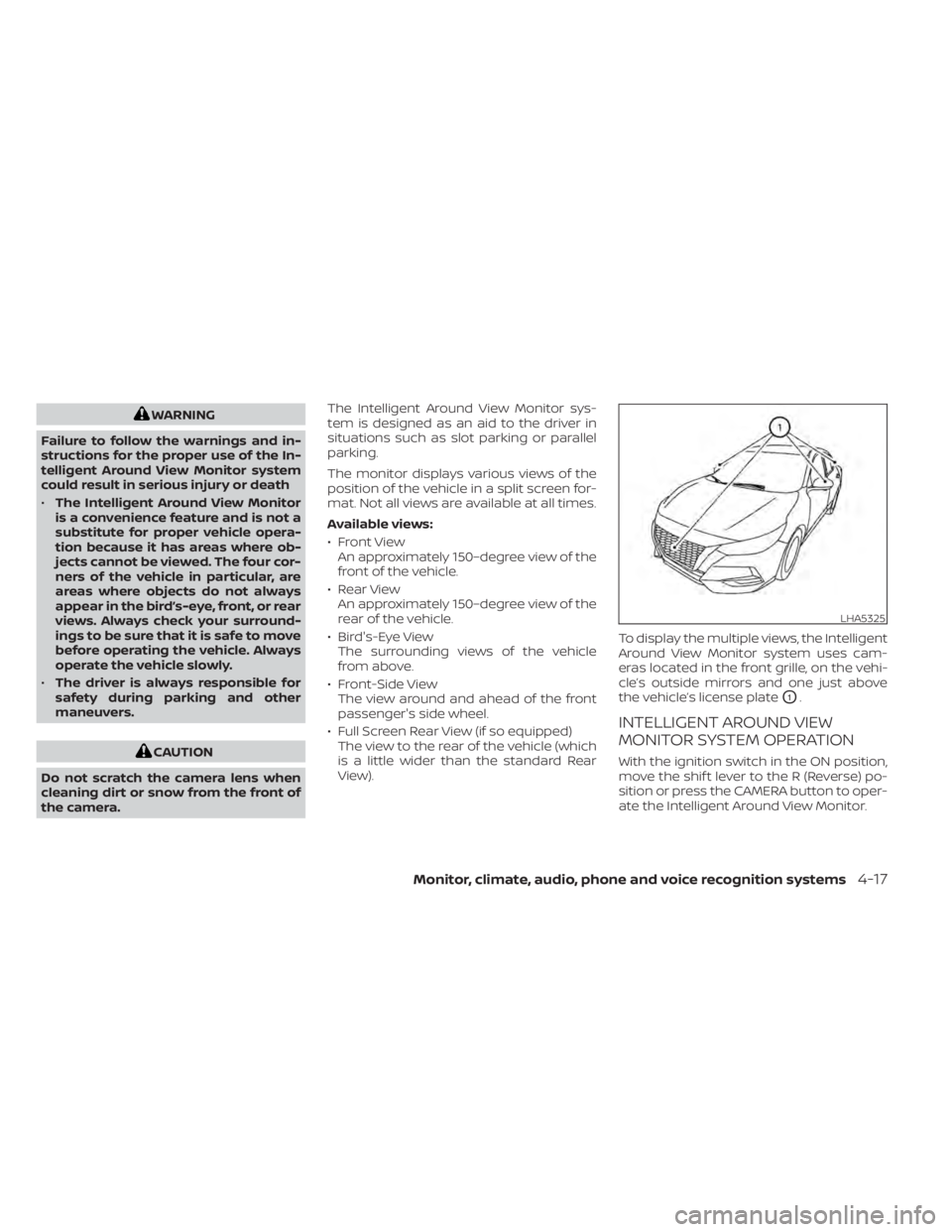
View). To display the multiple views, the Intelligent
Around View Monitor system uses cam-
eras located in the front grille, on the vehi-
cle’s outside mirrors and one just above
the vehicle’s license plate
O1.
INTELLIGENT AROUND VIEW
MONITOR SYSTEM OPERATION
With the ignition switch in the ON position,
move the shif t lever to the R (Reverse) po-
sition or press the CAMERA button to oper-
ate the Intelligent Around View Monitor.
LHA5325
Page 223 of 528

Front-side view
Guiding lines
Guiding lines that indicate the approximate
width and the front end of the vehicle are
displayed on the monitor.
The front-of-vehicle line
O1shows the front
part of the vehicle.
The side-of-vehicle line
O2shows the ap-
proximate vehicle width including the out-
side mirrors.
The extensions
O3of both the frontO1and
side
O2lines are shown with a green dotted
line.
DIFFERENCE BETWEEN PREDICTED
AND ACTUAL DISTANCES
The displayed guidelines and their loca-
tions on the ground are for approximate
reference only. Objects on uphill or downhill
surfaces or projecting objects will be actu-
ally located at distances different from
those displayed in the monitor relative to
the guidelines (refer to illustrations). When
in doubt, turn around and view the objects
as you are backing up, or park and exit the
vehicle to view the positioning of objects
behind the vehicle.
Backing up on a steep uphill
When backing up the vehicle up a hill, the
distance guide lines and the vehicle width
guide lines are shown closer than the ac-
tual distance. Note that any object on the
hill is further than it appears on the
monitor.
LHA2652
LHA5322
Page 231 of 528

WARNING
Failure to follow the warnings and in-
structions for proper use of the Moving
Object Detection (MOD) system could
result in serious injury or death
• The MOD system is not a substitute
for proper vehicle operation and is
not designed to prevent contact with
objects surrounding the vehicle.
When maneuvering, always use the
outside mirrors and rearview mirror
and turn and check the surroundings
to ensure it is safe to maneuver.
• The system is deactivated at speeds
above 5 mph (8 km/h). It is reacti-
vated at lower speeds.
• The MOD system is not designed to
detect surrounding stationary
objects.
The MOD system can inform the driver of
moving objects near the vehicle when
backing out of garages, maneuvering in
parking lots and in other such instances.
The MOD system detects moving objects
by using image processing technology on
the image shown in the display.
MOD SYSTEM OPERATION
The MOD system will turn on automatically
under the following conditions:
• When the shif t lever is in the R (Reverse) position.
• When the CAMERA button is pressed to activate the camera view on the display.
• When vehicle speed decreases below ap- proximately 6 mph (10 km/h) and the
camera screen is displayed. The MOD system operates in the following
conditions when the camera view is dis-
played:
• When the shif t lever is in the P (Park) or N
(Neutral) position and the vehicle is
stopped, the MOD system detects mov-
ing objects in the bird’s-eye view. The
MOD system will not operate if the out-
side mirrors are moving in or out, in the
stowed position, or if either front door is
opened.
LHA4190
Front and bird’s-eye views
Monitor, climate, audio, phone and voice recognition systems4-29
Page 235 of 528
1.Fan speed control dial
2.Heated seat switches (if so
equipped)
3.
Front defroster button
4.Rear window and outside mirror
(if so equipped) defroster switch
5.
Air recirculation button
6. MAX A/C / temperature control dial 7. Air flow control buttons
8. A/C (air conditioner) button
Monitor, climate, audio, phone and voice recognition systems4-33
Page 236 of 528

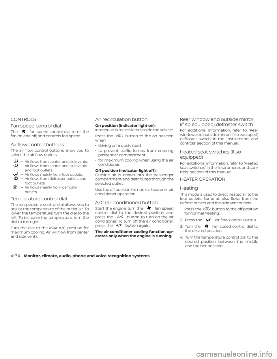
CONTROLS
Fan speed control dial
Thefan speed control dial turns the
fan on and off, and controls fan speed.
Air flow control buttons
The air flow control buttons allow you to
select the air flow outlets.
— Air flows from center and side vents.— Air flows from center and side vents
and foot outlets.
— Air flows mainly from foot outlets.— Air flows from defroster outlets andfoot outlets.
— Air flows mainly from defrosteroutlets.
Temperature control dial
The temperature control dial allows you to
adjust the temperature of the outlet air. To
lower the temperature, turn the dial to the
lef t. To increase the temperature, turn the
dial to the right.
Turn the dial to the MAX A/C position for
maximum cooling. Air will flow from center
and side vents.
Air recirculation button
On position (Indicator light on):
Interior air is recirculated inside the vehicle.
Press the
button to the on position
when:
• driving on a dusty road.
• to prevent traffic fumes from entering passenger compartment.
• for maximum cooling when using the air conditioner.
Off position (Indicator light off ):
Outside air is drawn into the passenger
compartment and distributed through the
selected outlet.
Use the off position for normal heater or air
conditioner operation.
A/C (air conditioner) button
Start the engine, turn thefan speed
control dial to the desired position and
press the
button to turn on the air
conditioner. To turn off the air conditioner,
press the
button again.
The air conditioner cooling function op-
erates only when the engine is running.
Rear window and outside mirror
(if so equipped) defroster switch
For additional information, refer to “Rear
window and outside mirror (if so equipped)
defroster switch” in the “Instruments and
controls” section of this manual.
Heated seat switches (if so
equipped)
For additional information, refer to “Heated
seat switches” in the “Instruments and con-
trols” section of this manual.
HEATER OPERATION
Heating
This mode is used to direct heated air to the
foot outlets. Some air also flows from the
defrost outlets and the side vent outlets.
1. Press thebutton to the off position
for normal heating.
2. Press the
air flow control button.
3. Turn the
fan speed control dial to
the desired position.
4. Turn the temperature control dial to the desired position between the middle
and the hot position.
4-34Monitor, climate, audio, phone and voice recognition systems
Page 242 of 528
1. AUTO (automatic) climate control but-ton / temperature control dial (drivers
side)
2. Display screen
3.
Heated seat switches (if so
equipped) 4. SYNC button / temperature control dial
(passenger’s side)
5. A/C (air conditioner) button
6.Air recirculation button
7.Air flow control button
8.Fan speed control buttons
9.Heated steering wheel switch (if
so equipped) 10.
Rear window and outside mirror
defroster switch
11.
Front defroster button
12. ON-OFF button
LHA4784
HEATER AND AIR CONDITIONER
(automatic) (if so equipped)