2021 NISSAN MURANO fuse
[x] Cancel search: fusePage 15 of 508
20. Bluetooth® Hands-Free Phone System/Audio control switches*
21. Hood release (P. 3-21) Fuel door release (P. 3-29)
22. Fuse box (P. 8-19)
23. Heated steering wheel switch
(if so equipped) (P. 2-46)
Dynamic driver assistance switch
(P. 2-47)
Lif tgate instrument panel switch
(if so equipped) (P. 3-22)
Vehicle Dynamic Control (VDC) OFF
switch (P. 2-47)
24. Instrument brightness control (P. 2-40) Twin trip odometer reset switch (P. 2-4)
*: Refer to the separate NissanConnect®
Owner's Manual.
Refer to the page number indicated in
parentheses for operating details.
Illustrated table of contents0-7
Page 16 of 508

3.5L 6 cylinder (VQ35DE engine model)
1. Engine coolant reservoir (P. 8-4)
2. Drive belt location (P. 8-15)
3. Engine oil dipstick (P. 8-6)4. Engine oil filler cap (P. 8-6)
5. Brake fluid reservoir (P. 8-11)
6. Air cleaner (P. 8-16)
7. Fuse box (P. 8-19)8. Fuse/Fusible link box (P. 8-19)
9. Battery (P. 8-13)
10. Radiator cap (P. 8-4)
11. Power steering fluid reservoir (P. 8-11)
12. Windshield-washer fluid reservoir
(P. 8-12)
Refer to the page number indicated in
parentheses for operating details.
LDI3345
ENGINE COMPARTMENT CHECK
LOCATIONS
0-8Illustrated table of contents
Page 95 of 508
20. Bluetooth® Hands-Free Phone System/Audio control switches*
21. Hood release (P. 3-21) Fuel door release (P. 3-29)
22. Fuse box (P. 8-19)
23. Heated steering wheel switch
(if so equipped) (P. 2-46)
Dynamic driver assistance switch
(P. 2-47)
Lif tgate instrument panel switch
(if so equipped) (P. 3-22)
Vehicle Dynamic Control (VDC) OFF
switch (P. 2-47)
24. Instrument brightness control (P. 2-40) Twin trip odometer reset switch (P. 2-4)
*: Refer to the separate NissanConnect®
Owner's Manual.
Refer to the page number indicated in
parentheses for operating details.
Instruments and controls2-3
Page 118 of 508
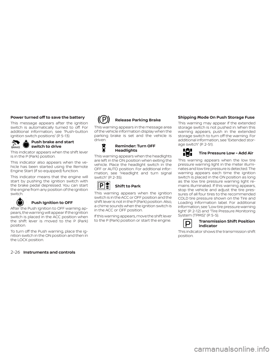
Power turned off to save the battery
This message appears af ter the ignition
switch is automatically turned to off. For
additional information, see “Push-button
ignition switch positions” (P. 5-13)
Push brake and start
switch to drive
This indicator appears when the shif t lever
is in the P (Park) position.
This indicator also appears when the ve-
hicle has been started using the Remote
Engine Start (if so equipped) function.
This indicator means that the engine will
start by pushing the ignition switch with
the brake pedal depressed. You can start
the engine from any position of the ignition
switch.
Push Ignition to OFF
Af ter the Push Ignition to OFF warning ap-
pears, the warning will appear if the ignition
switch is placed in the ACC position when
the shif t lever is moved to the P (Park)
position.
To turn off the Push warning, place the ig-
nition switch in the ON position and then in
the LOCK position.
Release Parking Brake
This warning appears in the message area
of the vehicle information display when the
parking brake is set and the vehicle is
driven.
Reminder: Turn OFF
Headlights
This warning appears when the headlights
are lef t in the ON position when exiting the
vehicle. Place the headlight switch in the
OFF or AUTO position. For additional infor-
mation, see “Headlight and turn signal
switch” (P. 2-35).
Shif t to Park
This warning appears when the ignition
switch is in the ACC or OFF position and the
shif t lever is not in the P (Park) position. Also,
a chime sounds when the ignition switch is
in the ACC or OFF position.
If this warning appears, move the shif t lever
to the P (Park) position or start the engine.
Shipping Mode On Push Storage Fuse
This warning may appear if the extended
storage switch is not pushed in. When this
warning appears, push in the extended
storage switch to turn off the warning. For
additional information, see “Extended stor-
age switch” (P. 2-51).
Tire Pressure Low - Add Air
This warning appears when the low tire
pressure warning light in the meter illumi-
nates and low tire pressure is detected. The
warning appears each time the ignition
switch is placed in the ON position as long
as the low tire pressure warning light re-
mains illuminated. If this warning appears,
stop the vehicle and adjust the tire pres-
sures of all four tires to the recommended
COLD tire pressure shown on the Tire and
Loading Information label. For additional
information, see “Low tire pressure warning
light” (P. 2-12) and “Tire Pressure Monitoring
System (TPMS)” (P. 5-5).
Transmission Shif t Position
indicator
This indicator shows the transmission shif t
position.
2-26Instruments and controls
Page 143 of 508
•Do not use double adapters or more
than one electrical accessory.
• Use power outlets with the engine
running to avoid discharging the ve-
hicle battery.
• Avoid using power outlets when the
air conditioner, headlights or rear
window defroster is on.
• Before inserting or disconnecting a
plug, be sure the electrical accessory
being used is turned off.
• Push the plug in as far as it will go. If
good contact is not made, the plug
may overheat or the internal tem-
perature fuse may open.
• When not in use, be sure to close the
cap. Do not allow water or any other
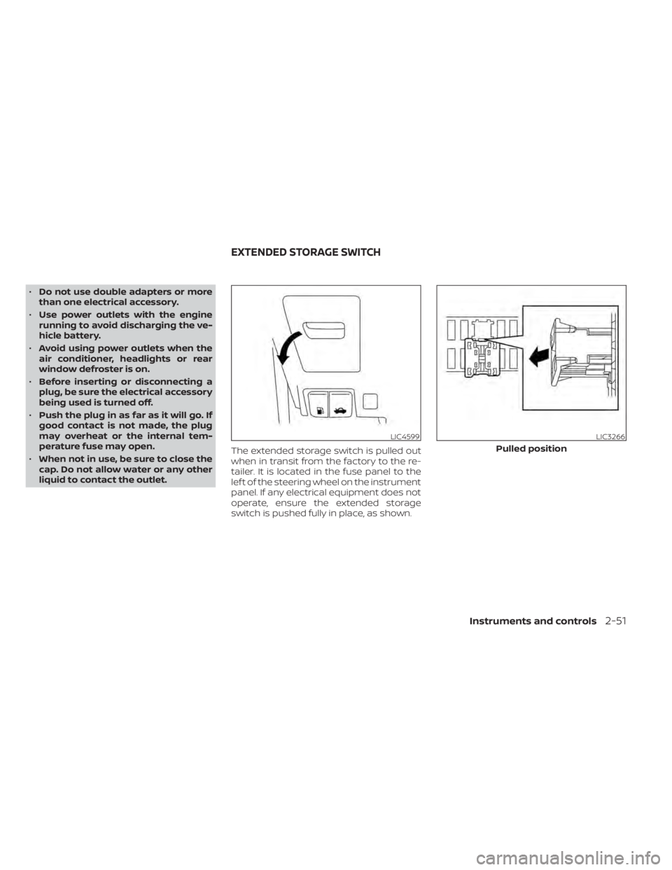
liquid to contact the outlet. The extended storage switch is pulled out
when in transit from the factory to the re-
tailer. It is located in the fuse panel to the
lef t of the steering wheel on the instrument
panel. If any electrical equipment does not
operate, ensure the extended storage
switch is pushed fully in place, as shown.
LIC4599LIC3266
Pulled position
EXTENDED STORAGE SWITCH
Instruments and controls2-51
Page 202 of 508
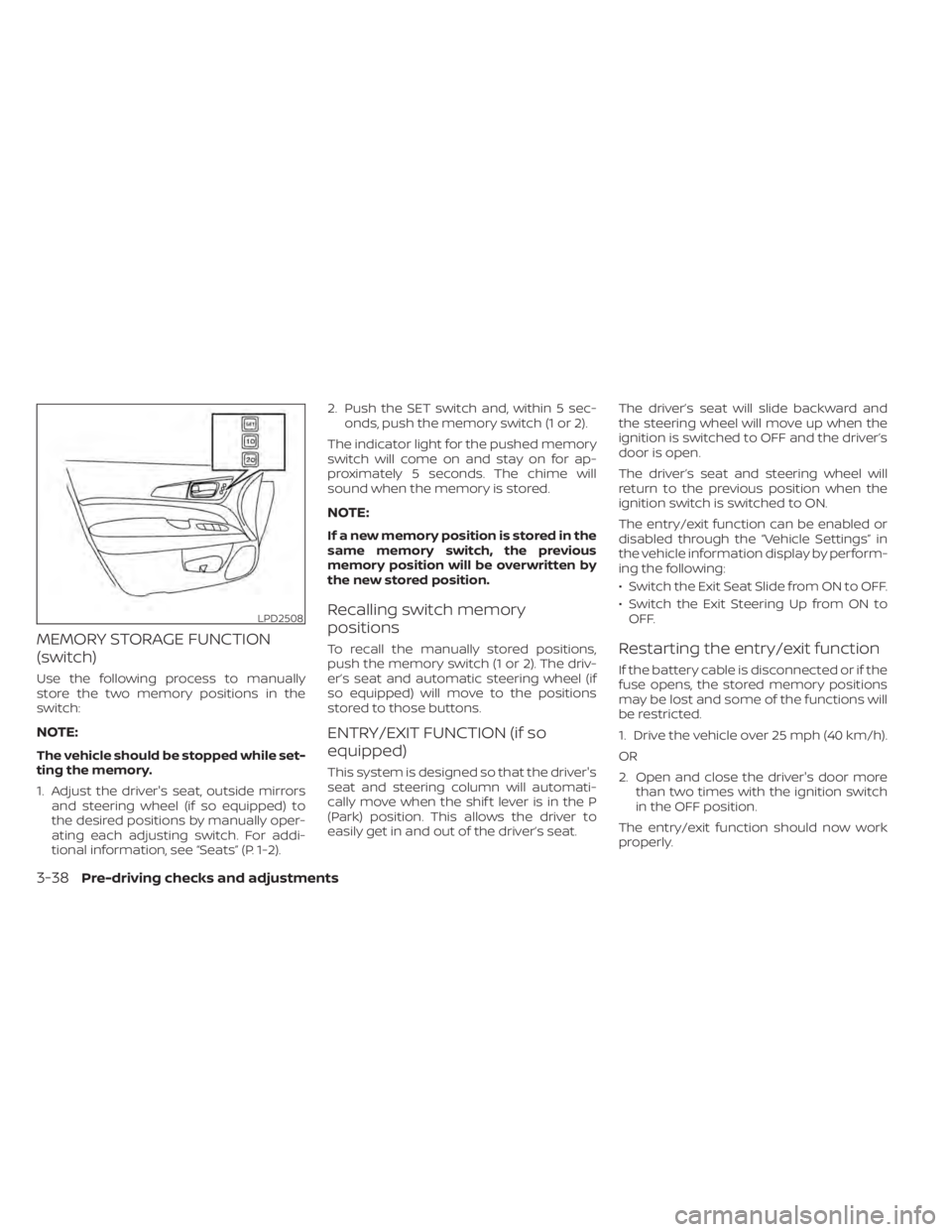
MEMORY STORAGE FUNCTION
(switch)
Use the following process to manually
store the two memory positions in the
switch:
NOTE:
The vehicle should be stopped while set-
ting the memory.
1. Adjust the driver's seat, outside mirrorsand steering wheel (if so equipped) to
the desired positions by manually oper-
ating each adjusting switch. For addi-
tional information, see “Seats” (P. 1-2). 2. Push the SET switch and, within 5 sec-
onds, push the memory switch (1 or 2).
The indicator light for the pushed memory
switch will come on and stay on for ap-
proximately 5 seconds. The chime will
sound when the memory is stored.
NOTE:
If a new memory position is stored in the
same memory switch, the previous
memory position will be overwritten by
the new stored position.
Recalling switch memory
positions
To recall the manually stored positions,
push the memory switch (1 or 2). The driv-
er’s seat and automatic steering wheel (if
so equipped) will move to the positions
stored to those buttons.
ENTRY/EXIT FUNCTION (if so
equipped)
This system is designed so that the driver's
seat and steering column will automati-
cally move when the shif t lever is in the P
(Park) position. This allows the driver to
easily get in and out of the driver’s seat. The driver’s seat will slide backward and
the steering wheel will move up when the
ignition is switched to OFF and the driver’s
door is open.
The driver’s seat and steering wheel will
return to the previous position when the
ignition switch is switched to ON.
The entry/exit function can be enabled or
disabled through the “Vehicle Settings” in
the vehicle information display by perform-
ing the following:
• Switch the Exit Seat Slide from ON to OFF.
• Switch the Exit Steering Up from ON to
OFF.
Restarting the entry/exit function
If the battery cable is disconnected or if the
fuse opens, the stored memory positions
may be lost and some of the functions will
be restricted.
1. Drive the vehicle over 25 mph (40 km/h).
OR
2. Open and close the driver's door more than two times with the ignition switch
in the OFF position.
The entry/exit function should now work
properly.
LPD2508
3-38Pre-driving checks and adjustments
Page 391 of 508

8 Do-it-yourself
Maintenance precautions.......................8-2
Engine compartment check locations ...........8-3
Engine cooling system ..........................8-4
Checking engine coolant level ................8-5
Changing engine coolant ....................8-5
Engine oil .......................................8-6
Checking engine oil level .....................8-6
Changing engine oil and oil filter ..............8-6
Continuously Variable Transmission (CVT)
fluid ............................................ 8-10
Power Steering Fluid (PSF) .......................8-11
Brake fluid ....................................... 8-11
Windshield-washer fluid ........................8-12
Windshield-washer fluid reservoir ...........8-12
Battery......................................... 8-13
Jump starting ............................... 8-14
Drive belt ....................................... 8-15
Spark plugs .................................... 8-15
Replacing spark plugs ....................... 8-15
Air cleaner ..................................... 8-16In-cabin microfilter
.......................... 8-17
Windshield wiper blades ........................8-17
Cleaning .................................... 8-17
Replacing ................................... 8-17
Brakes ......................................... 8-19
Fuses .......................................... 8-19
Engine compartment .......................8-20
Passenger compartment ...................8-21
Battery replacement ........................... 8-23
NISSAN Intelligent Key® ......................8-23
Lights .......................................... 8-25
Headlights .................................. 8-25
Fog lights (if so equipped) ...................8-25
Exterior and interior lights ...................8-25
Wheels and tires ............................... 8-27
Tire pressure ................................ 8-27
Tire labeling ................................. 8-30
Types of tires ................................
8-33
Tir
e chains .................................. 8-34
Changing wheels and tires ..................8-35
Page 393 of 508

3.5L 6 cylinder (VQ35DE engine model)
1. Engine coolant reservoir
2. Drive belt location
3. Engine oil dipstick4. Engine oil filler cap
5. Brake fluid reservoir
6. Air cleaner
7. Fuse box8. Fuse/Fusible link box
9. Battery
10 Radiator cap
11. Power steering fluid reservoir
12. Windshield-washer fluid reservoir
LDI3345
ENGINE COMPARTMENT CHECK
LOCATIONS
Do-it-yourself8-3