2021 NISSAN MURANO flat tire
[x] Cancel search: flat tirePage 425 of 508

CHANGING WHEELS AND TIRES
Tire rotation
NISSAN recommends rotating the
tires every 7,500 miles (12,000 km).
For additional information on tire re-
placing procedures, see “Flat tire”
(P. 6-3).
As soon as possible, tighten the
wheel nuts to the specified torque
with a torque wrench.Wheel nut tightening torque:
83 f t-lb (113 N·m)
The wheel nuts must be kept tight-
ened to specifications at all times.
It is recommended that wheel nuts
be tightened to specification at
each tire rotation interval.
WARNING
•
Af ter rotating the tires, check
and adjust the tire pressure.
•Retighten the wheel nuts when
the vehicle has been driven for
600 miles (1,000 km) (also in
cases of a flat tire, etc.).
•Do not include the spare tire in
the tire rotation.
•For additional information re-
garding tires, refer to “Impor-
tant Tire Safety Information”
(US) or “Tire Safety Information”
(Canada) in the Warranty Infor-
mation Booklet.
Tire wear and damage
1. Wear indicator
2. Location mark
WDI0258WDI0259
Do-it-yourself8-35
Page 428 of 508
Spare tire (TEMPORARY USE ONLY
spare tire)
When using a wheel without the TPMS such
as the spare tire, the TPMS will not function.
Observe the following precautions if the
TEMPORARY USE ONLY spare tire must be
used. Otherwise, your vehicle could be
damaged or involved in an accident:
WARNING
• The spare tire should be used for
emergency use only. It should be re-
placed with the standard tire at the
first opportunity to avoid possible
tire or differential damage.
• Drive carefully while the TEMPORARY
USE ONLY spare tire is installed. Avoid
sharp turns and abrupt braking while
driving.
• Periodically check spare tire inflation
pressure. Always keep the pressure
of the TEMPORARY USE ONLY spare
tire at 420 kPa, 4.2 bar (60 psi).
• With the TEMPORARY USE ONLY spare
tire installed do not drive the vehicle
at speeds faster than 50 mph (80
km/h). •
When driving on roads covered with
snow or ice, the TEMPORARY USE
ONLY spare tire should be used on the
rear wheels and the original tire used
on the front wheels (drive wheels).
• Tire tread of the TEMPORARY USE
ONLY spare tire will wear at a faster
rate than the standard tire. Replace
the spare tire as soon as the tread
wear indicators appear.
• Do not use the spare tire on other
vehicles.
• Do not use more than one spare tire
at the same time.
• Do not tow a trailer when the TEMPO-
RARY USE ONLY spare tire is installed.
CAUTION
• Do not use tire chains on a TEMPO-
RARY USE ONLY spare tire. Tire chains
will not fit properly and may cause
damage to the vehicle.
• Because the TEMPORARY USE ONLY
spare tire is smaller than the original
tire, ground clearance is reduced. To
avoid damage to the vehicle, do not
drive over obstacles. Also, do not
drive the vehicle through an auto-
matic car wash since it may get
caught.
8-38Do-it-yourself
Page 461 of 508

10 Technical and consumer information
Recommended fluids/lubricants and
capacities...................................... 10-2
Fuel recommendation ......................10-4
Engine oil and oil filter
recommendations .......................... 10-7
Air conditioner system refrigerant and
oil recommendations .......................10-8
Specifications .................................. 10-9
Engine ...................................... 10-9
Wheels and tires ........................... 10-10
Dimensions and weights ...................10-10
When traveling or registering in another
country ........................................ 10-11
Vehicle identification ........................... 10-11
Vehicle Identification Number (VIN)
plate ........................................ 10-11
Vehicle identification number
(chassis number) ............................ 10-11
Engine serial number ......................10-12
F.M.V.S.S./C.M.V.S.S. certification label ........10-12
Emission control information label .........10-12
Tire and Loading Information label .........10-13
Air conditioner specification label ..........10-13
Installing front license plate ...................10-14Vehicle loading information
...................10-15
Terms ...................................... 10-15
Vehicle load capacity ....................... 10-16
Securing the load .......................... 10-17
Loading tips ................................ 10-18
Measurement of weights ...................10-19
Towing a trailer ................................ 10-19
Maximum load limits ....................... 10-19
Towing load/specification ..................10-23
Towing safety .............................. 10-24
Flat towing for all–wheel drive vehicle
(if so equipped) ............................. 10-28
Flat towing for front wheel drive vehicle
(if so equipped) ............................. 10-28
Uniform tire quality grading ...................10-29
Emission control system warranty ............10-30
Reporting safety defects ......................10-31
Readiness for Inspection/Maintenance (I/M)
test ........................................... 10-32
E
vent Data Recorders (EDR) ...................10-32
Owner's Manual/Service Manual order
information ................................... 10-33
Page 477 of 508
cargo should never exceed XXX
lbs. or XXX kg” on your vehicle’s
placard.
2. Determine the combined weight of the driver and passengers that
will be riding in your vehicle.
3. Subtract the combined weight of the driver and passengers from
XXX lbs. or XXX kg.
4. The resulting figure equals the available amount of cargo and
luggage load capacity. For ex-
ample, if the XXX amount equals
1,400 lbs. and there will be five 150
lbs. passengers in your vehicle,
the amount of available cargo
and luggage load capacity is 650
lbs. (1,400-750 (5 X 150) = 650 lbs.) or
(640-340 (5 X 70) = 300 kg.) 5. Determine the combined weight
of luggage and cargo being
loaded on the vehicle. That weight
may not safely exceed the avail-
able cargo and luggage load ca-
pacity calculated in step 4.
6. If your vehicle will be towing a trailer, load from your trailer will be
transferred to your vehicle. Con-
sult this manual to determine
how this reduces the available
cargo and luggage load capacity
of your vehicle.
Before driving a loaded vehicle, con-
firm that you do not exceed the
GVWR or the GAWR for your vehicle.
For additional information, see “Mea-
surement of weights” (P. 10-19).
Also check tires for proper inflation
pressures. For additional informa-
tion, see “Tire and Loading Informa-
tion label” (P. 10-13).
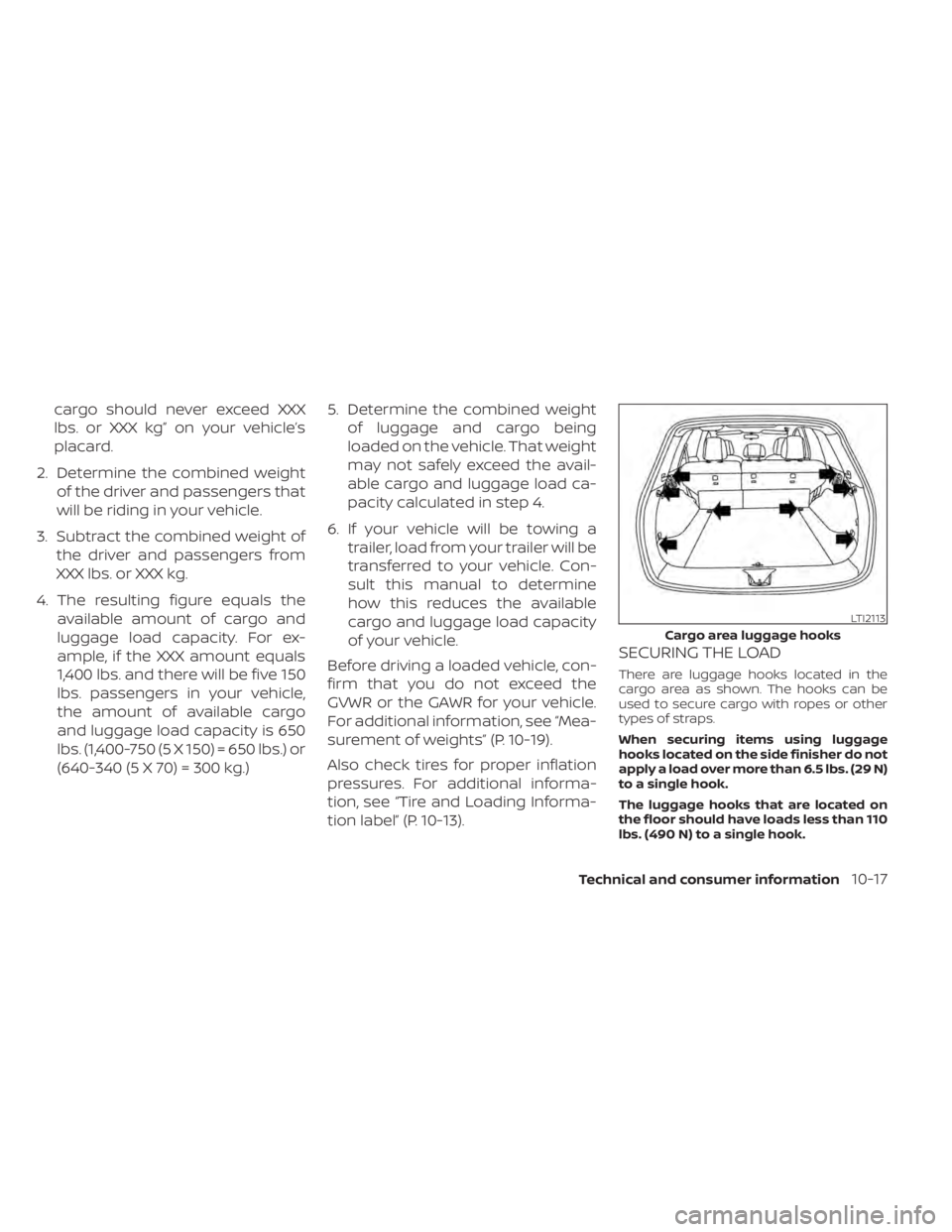
SECURING THE LOAD
There are luggage hooks located in the
cargo area as shown. The hooks can be
used to secure cargo with ropes or other
types of straps.
When securing items using luggage
hooks located on the side finisher do not
apply a load over more than 6.5 lbs. (29 N)
to a single hook.
The luggage hooks that are located on
the floor should have loads less than 110
lbs. (490 N) to a single hook.
LTI2113
Cargo area luggage hooks
Technical and consumer information10-17
Page 485 of 508

A weight-distributing hitch system (Class
IV) is recommended if you plan to tow trail-
ers with a maximum weight over 5,000 lbs.
(2,268 kg). Check with the trailer and towing
equipment manufacturers to determine if
they recommend the use of a weight-
distributing hitch system.
NOTE:
A weight-distributing hitch system may
affect the operation of trailer surge
brakes. If you are considering use of a
weight-distributing hitch system with a
surge brake-equipped trailer, check with
the surge brake, hitch or trailer manufac-
turer to determine if and how this can be
done.
Follow the instructions provided by the
manufacturer for installing and using the
weight-distributing hitch system.
General set-up instructions are as follows:
1. Park unloaded vehicle on a level surface.With the ignition switch in the ON posi-
tion and the doors closed, allow the ve-
hicle to stand for several minutes so that
it can level.
2. Measure the height of a reference point on the front and rear bumpers at the
center of the vehicle. 3. Attach the trailer to the vehicle and ad-
just the hitch equalizers so that the front
bumper height is within0-.5inches (0 –
13 mm) of the reference height mea-
sured in step 2. The rear bumper should
be no higher than the reference height
measured in step 2.
WARNING
Properly adjust the weight distributing
hitch so the rear of the bumper is no
higher than the measured reference
height when the trailer is attached. If
the rear bumper is higher than the
measured reference height when
loaded, the vehicle may handle unpre-
dictably which could cause a loss of ve-
hicle control and cause serious per-
sonal injury or property damage.
Sway control device
Sudden maneuvers, wind gusts, and buf-
feting caused by other vehicles can affect
trailer handling. Sway control devices may
be used to help control these affects. If you
choose to use one, contact a reputable
trailer hitch supplier to make sure the sway
control device will work with the vehicle,
hitch, trailer and the trailer's brake system.
Follow the instructions provided by the manufacturer for installing and using the
sway control device.
Class I hitch
Class I trailer hitch equipment (receiver, ball
mount and hitch ball) can be used to tow
trailers of a maximum weight of 2,000 lbs.
(907 kg).
Tire pressures
• When towing a trailer, inflate the
vehicle tires to the recommended
cold tire pressure indicated on the
Tire and Loading Information label.
• Trailer tire condition, size, load rat- ing and proper inflation pressure
should be in accordance with the
trailer and tire manufacturer's
specifications.
Safety chains
Always use suitable safety chains between
your vehicle and the trailer. The safety
chains should be crossed and should be
attached to the hitch, not to the vehicle
bumper or axle. The safety chains can be
attached to the bumper if the hitch ball is
Technical and consumer information10-25
Page 486 of 508
mounted to the bumper. Be sure to leave
enough slack in the chains to permit turn-
ing corners.
Trailer lights
CAUTION
When splicing into the vehicle electrical
system, a commercially available
power-type module/converter must
be used to provide power for all trailer
lighting. This unit uses the vehicle bat-
tery as a direct power source for all
trailer lights while using the vehicle tail
light, stop light and turn signal circuits
as a signal source. The module/
converter must draw no more than 15
milliamps from the stop and tail lamp
circuits. Using a module/converter that
exceeds these power requirements
may damage the vehicle's electrical
system. It is recommended that you
visit a reputable trailer retailer to ob-
tain the proper equipment and to have
it installed.
Trailer lights should comply with federal
and/or local regulations. For assistance in
hooking up trailer lights, it is recommended
that you contact a NISSAN dealer or repu-
table trailer retailer. Vehicles equipped with the optional trailer tow package are
equipped with a flat 4-pin connector, an
adapter will be needed to connect the
trailer lights to the vehicle. Adapters are
available at auto parts stores and hitch
retailers.Pre-towing tips
• Be certain your vehicle maintains a level
position when a loaded and/or unloaded
trailer is hitched. Do not drive the vehicle if
it has an abnormal nose-up or nose-
down condition; check for improper
tongue load, overload, worn suspension
or other possible causes of either
condition.
• Always secure items in the trailer to pre- vent load shif t while driving.
• Keep the cargo load as low as possible in the trailer to keep the trailer center of
gravity low.
• Load the trailer so approximately 60% of the trailer load is in the front half and 40%
is in the back half. Also make sure the load
is balanced side to side.
• Check your hitch, trailer tire pressure, ve- hicle tire pressure, trailer light operation,
and trailer wheel lug nuts every time you
attach a trailer to the vehicle. • Be certain your rearview mirrors conform
to all federal, state or local regulations. If
not, install any mirrors required for towing
before driving the vehicle.
• Determine the overall height of the ve- hicle and trailer so the required clearance
is known.Trailer towing tips
In order to gain skill and an understanding
of the vehicle's behavior, you should prac-
tice turning, stopping and backing up in an
area which is free from traffic. Steering sta-
bility and braking performance will be
somewhat different than under normal
driving conditions.
• Always secure items in the trailer to pre-vent load shif t while driving.
• Lock the trailer hitch coupler with a pin or lock to prevent the coupler from inadver-
tently becoming unlatched.
• Avoid abrupt starts, acceleration or stops.
• Avoid sharp turns or lane changes.
• Always drive your vehicle at a moderate speed.
10-26Technical and consumer information
Page 489 of 508
CAUTION
• Failure to follow these guidelines can
result in severe transmission
damage.
• Whenever flat towing your vehicle,
always tow forward, never backward.
• Never tow your front wheel drive ve-
hicle with the front tires on the
ground. Doing so may cause serious
and expensive damage to the
powertrain.
• DO NOT tow your front wheel drive
continuously variable transmission
vehicle with all four wheels on the
ground (flat towing). Doing so WILL
DAMAGE internal transmission parts
due to lack of transmission
lubrication.
• For emergency towing procedures
see “Towing recommended by
NISSAN” (P. 6-13).Continuously Variable
Transmission
To tow a vehicle equipped with a continu-
ously variable transmission, an appropriate
vehicle dolly MUSTbe placed under the
towed vehicle's drive wheels. Alwaysfollow
the dolly manufacturer's recommenda-
tions when using their product. DOT (Department of Transportation) Qual-
ity Grades: All passenger car tires must
conform to federal safety requirements in
addition to these grades.
Quality grades can be found where appli-
cable on the tire sidewall between tread
shoulder and maximum section width. For
example:
Treadwear 200 Traction AA Temperature A
Treadwear
The treadwear grade is a comparative rat-
ing based on the wear rate of the tire when
tested under controlled conditions on a
specified government test course. For ex-
ample, a tire graded 150 would wear one
and one-half (1 1/2) times as well on the
government course as a tire graded 100.
The relative performance of tires depends
upon the actual conditions of their use,
however, and may depart significantly from
the norm due to variations in driving habits,
service practices and differences in road
characteristics and climate.
UNIFORM TIRE QUALITY GRADING
Technical and consumer information10-29
Page 490 of 508
Traction AA, A, B and C
The traction grades, from highest to low-
est, are AA, A, B, and C. Those grades repre-
sent the tire's ability to stop on wet pave-
ment as measured under controlled
conditions on specified government test
surfaces of asphalt and concrete. A tire
marked C may have poor traction
performance.
WARNING
The traction grade assigned to this tire
is based on straight-ahead braking
traction tests, and does not include ac-
celeration, cornering, hydroplaning, or
peak traction characteristics.
Temperature A, B and C
The temperature grades are A (the high-
est), B, and C, representing the tire’s resis-
tance to the generation of heat, and its
ability to dissipate heat when tested under
controlled conditions on a specified indoor
laboratory test wheel. Sustained high tem-
perature can cause the material of the tire
to degenerate and reduce tire life, and ex-
cessive temperature can lead to sudden
tire failure. The grade C corresponds to a
level of performance which all passenger
car tires must meet under the Federal Mo- tor Vehicle Safety Standard No. 109. Grades
B and A represent higher levels of perfor-
mance on the laboratory test wheel than
the minimum required by law.
WARNING
The temperature grade for this tire is
established for a tire that is properly
inflated and not overloaded. Excessive
speed, under-inflation, or excessive
loading, either separately or in combi-
nation, can cause heat build-up and
possible tire failure. Your NISSAN vehicle is covered by the fol-
lowing emission warranties:
For USA
1. Emission Defects Warranty
2. Emissions Performance Warranty
Details of this warranty may be found with
other vehicle warranties in your Warranty
Information Booklet which comes with
your NISSAN vehicle. If you did not receive a
Warranty Information Booklet, or it is lost,
you may obtain a replacement by writing
to:
• Nissan North America, Inc.
Consumer Affairs Department
P.O. Box 685003
Franklin, TN 37068-5003
For Canada
Emission Control System Warranty
Details of this warranty may be found with
other vehicle warranties in your Warranty
Information Booklet which comes with
your NISSAN vehicle. If you did not receive a
Warranty Information Booklet, or it is lost,
you may obtain a replacement by writing
to:
• Nissan Canada Inc. 5290 Orbitor Drive
Mississauga, Ontario, L4W 4Z5
EMISSION CONTROL SYSTEM
WARRANTY
10-30Technical and consumer information