2021 NISSAN MURANO battery
[x] Cancel search: batteryPage 189 of 508
Auto Power Lif tgate System Battery
Power Saving Mode:
The vehicle goes into power saving mode
when the lif tgate is open for a long time
(approximately 12 hours). This is to prevent
deterioration of the battery. The power
saving mode automatically cuts the power
supply of the power lif tgate door.
When the power to the lif tgate is cut off, the
manual mode must be performed. Af ter
the manual mode is performed, the power
lif tgate function is restored.
NOTE:
When a battery voltage is lower than ap-
proximately 11V, the power lif tgate may
not operate af ter automatic return.
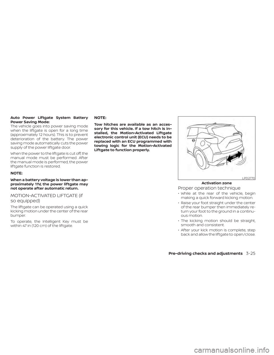
MOTION-ACTIVATED LIFTGATE (if
so equipped)
The lif tgate can be operated using a quick
kicking motion under the center of the rear
bumper.
To operate, the Intelligent Key must be
within 47 in (120 cm) of the lif tgate.
NOTE:
Tow hitches are available as an acces-
sory for this vehicle. If a tow hitch is in-
stalled, the Motion-Activated Lif tgate
electronic control unit (ECU) needs to be
replaced with an ECU programmed with
towing logic for the Motion-Activated
Lif tgate to function properly.
Proper operation technique
• While at the rear of the vehicle, beginmaking a quick forward kicking motion.
• Raise your foot straight under the center of the rear bumper then immediately re-
turn your foot to the ground in a continu-
ous motion.
• The kicking motion should be straight, smooth and consistent.
• Af ter your kick motion is complete, step back and allow the lif tgate to open/close.
LPD2770
Activation zone
Pre-driving checks and adjustments3-25
Page 191 of 508
CAUTION
• Interference or malfunction can be
caused by parking in close proximity
to radio or satellite towers.
• Intelligent Key interference could be
caused if you have your key fob
stored next to your cell phone or any
RF-enabled smart card. For addi-
tional information, see “NISSAN Intel-
ligent Key® system” (P. 3-7).
LIFTGATE RELEASE
WARNING
• Always be sure the lif tgate has been
closed securely to prevent it from
opening while driving.
• Do not drive with the lif tgate open.
This could allow dangerous exhaust
gases to be drawn into the vehicle.
For additional information, see “Ex-
haust gas (carbon monoxide)”
(P. 5-4).
• To avoid personal injury, do not at-
tempt to activate the power lif tgate
if one or both of the lif tgate struts are
removed.
CAUTION
• If the power lif tgate does not stay
open or if the lif tgate unexpectedly
closes at any time while a continuous
warning chime sounds, do not oper-
ate the lif tgate. There may be a pres-
sure loss in one or both of the lif tgate
struts. It is recommended that you
have the lif tgate inspected. It is rec-
ommended that you visit a NISSAN
dealer for this service.
• Do not activate the power lif tgate if
one or both of the lif tgate struts are
removed. Damage to the lif tgate or
power lif tgate mechanisms may
occur.
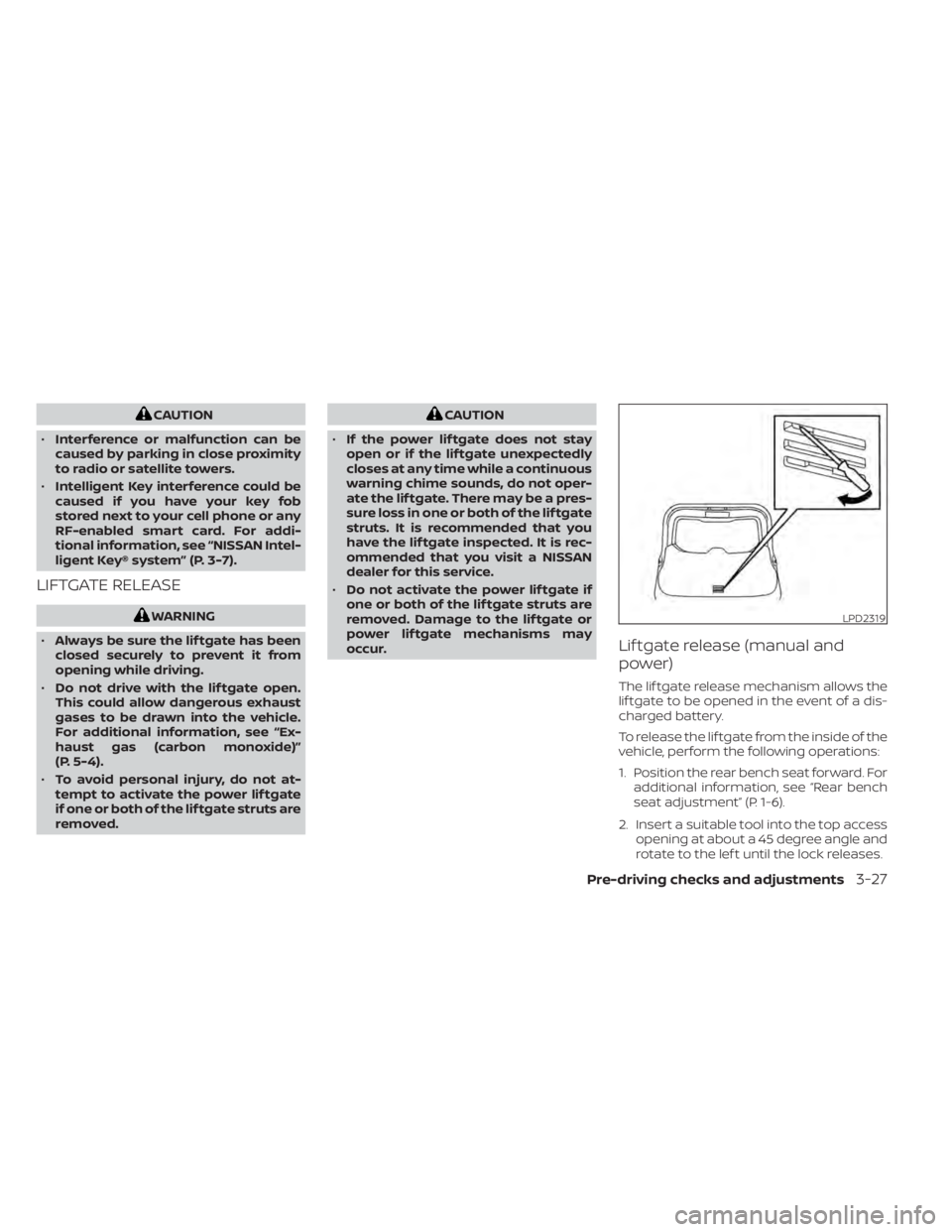
Lif tgate release (manual and
power)
The lif tgate release mechanism allows the
lif tgate to be opened in the event of a dis-
charged battery.
To release the lif tgate from the inside of the
vehicle, perform the following operations:
1. Position the rear bench seat forward. For additional information, see “Rear bench
seat adjustment” (P. 1-6).
2. Insert a suitable tool into the top access opening at about a 45 degree angle and
rotate to the lef t until the lock releases.
LPD2319
Pre-driving checks and adjustments3-27
Page 196 of 508
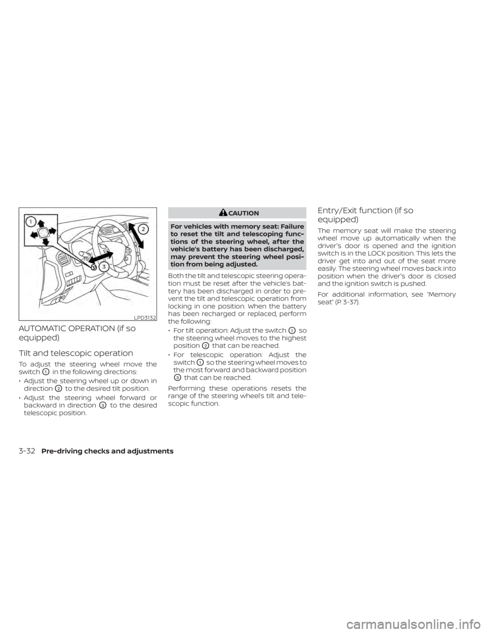
AUTOMATIC OPERATION (if so
equipped)
Tilt and telescopic operation
To adjust the steering wheel move the
switch
O1in the following directions:
• Adjust the steering wheel up or down in direction
O2to the desired tilt position.
• Adjust the steering wheel forward or backward in direction
O3to the desired
telescopic position.
CAUTION
For vehicles with memory seat: Failure
to reset the tilt and telescoping func-
tions of the steering wheel, af ter the
vehicle’s battery has been discharged,
may prevent the steering wheel posi-
tion from being adjusted.
Both the tilt and telescopic steering opera-
tion must be reset af ter the vehicle’s bat-
tery has been discharged in order to pre-
vent the tilt and telescopic operation from
locking in one position. When the battery
has been recharged or replaced, perform
the following:
• For tilt operation: Adjust the switch
O1so
the steering wheel moves to the highest
position
O2that can be reached.
• For telescopic operation: Adjust the switch
O1so the steering wheel moves to
the most forward and backward position
O3that can be reached.
Performing these operations resets the
range of the steering wheel’s tilt and tele-
scopic function.
Entry/Exit function (if so
equipped)
The memory seat will make the steering
wheel move up automatically when the
driver's door is opened and the ignition
switch is in the LOCK position. This lets the
driver get into and out of the seat more
easily. The steering wheel moves back into
position when the driver's door is closed
and the ignition switch is pushed.
For additional information, see “Memory
seat” (P. 3-37).
LPD3132
3-32Pre-driving checks and adjustments
Page 202 of 508
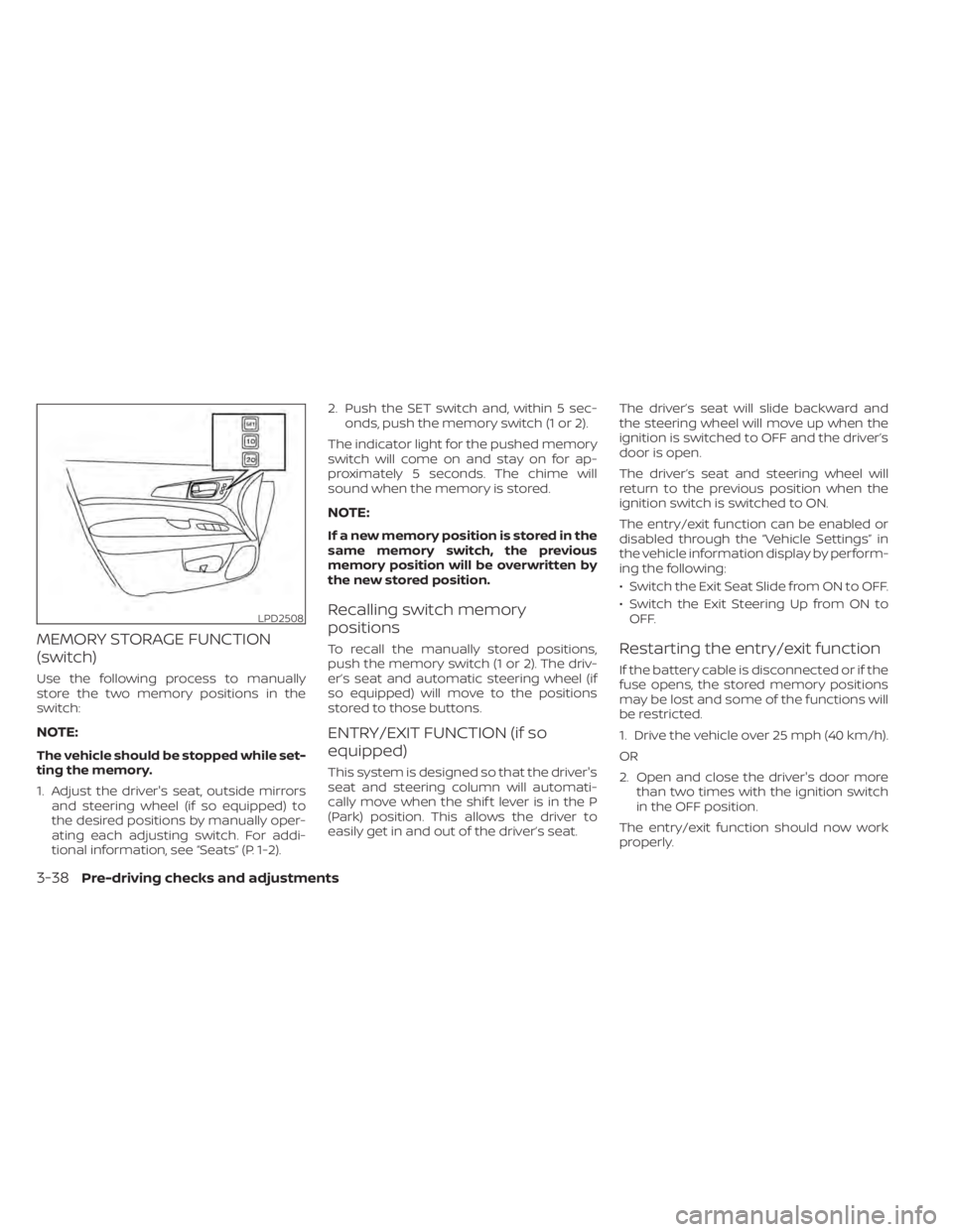
MEMORY STORAGE FUNCTION
(switch)
Use the following process to manually
store the two memory positions in the
switch:
NOTE:
The vehicle should be stopped while set-
ting the memory.
1. Adjust the driver's seat, outside mirrorsand steering wheel (if so equipped) to
the desired positions by manually oper-
ating each adjusting switch. For addi-
tional information, see “Seats” (P. 1-2). 2. Push the SET switch and, within 5 sec-
onds, push the memory switch (1 or 2).
The indicator light for the pushed memory
switch will come on and stay on for ap-
proximately 5 seconds. The chime will
sound when the memory is stored.
NOTE:
If a new memory position is stored in the
same memory switch, the previous
memory position will be overwritten by
the new stored position.
Recalling switch memory
positions
To recall the manually stored positions,
push the memory switch (1 or 2). The driv-
er’s seat and automatic steering wheel (if
so equipped) will move to the positions
stored to those buttons.
ENTRY/EXIT FUNCTION (if so
equipped)
This system is designed so that the driver's
seat and steering column will automati-
cally move when the shif t lever is in the P
(Park) position. This allows the driver to
easily get in and out of the driver’s seat. The driver’s seat will slide backward and
the steering wheel will move up when the
ignition is switched to OFF and the driver’s
door is open.
The driver’s seat and steering wheel will
return to the previous position when the
ignition switch is switched to ON.
The entry/exit function can be enabled or
disabled through the “Vehicle Settings” in
the vehicle information display by perform-
ing the following:
• Switch the Exit Seat Slide from ON to OFF.
• Switch the Exit Steering Up from ON to
OFF.
Restarting the entry/exit function
If the battery cable is disconnected or if the
fuse opens, the stored memory positions
may be lost and some of the functions will
be restricted.
1. Drive the vehicle over 25 mph (40 km/h).
OR
2. Open and close the driver's door more than two times with the ignition switch
in the OFF position.
The entry/exit function should now work
properly.
LPD2508
3-38Pre-driving checks and adjustments
Page 210 of 508
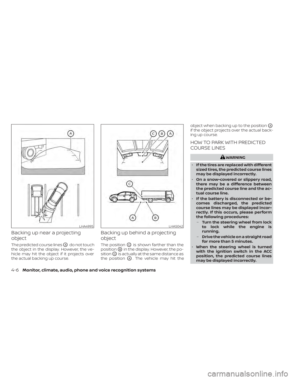
Backing up near a projecting
object
The predicted course linesOAdo not touch
the object in the display. However, the ve-
hicle may hit the object if it projects over
the actual backing up course.
Backing up behind a projecting
object
The positionOCis shown farther than the
position
OBin the display. However, the po-
sition
OCis actually at the same distance as
the position
OA. The vehicle may hit the object when backing up to the position
OA
if the object projects over the actual back-
ing up course.
HOW TO PARK WITH PREDICTED
COURSE LINES
WARNING
• If the tires are replaced with different
sized tires, the predicted course lines
may be displayed incorrectly.
• On a snow-covered or slippery road,
there may be a difference between
the predicted course line and the ac-
tual course line.
• If the battery is disconnected or be-
comes discharged, the predicted
course lines may be displayed incor-
rectly. If this occurs, please perform
the following procedures:
– Turn the steering wheel from lock
to lock while the engine is
running.
– Drive the vehicle on a straight road
for more than 5 minutes.
• When the steering wheel is turned
with the ignition switch in the ACC
position, the predicted course lines
may be displayed incorrectly.
LHA4995LHA5042
4-6Monitor, climate, audio, phone and voice recognition systems
Page 220 of 508
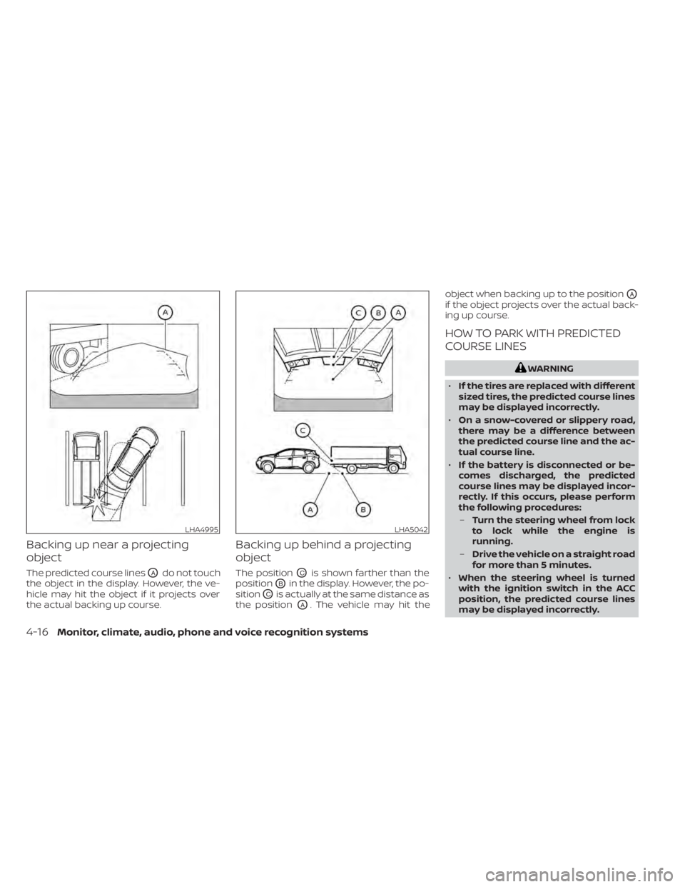
Backing up near a projecting
object
The predicted course linesOAdo not touch
the object in the display. However, the ve-
hicle may hit the object if it projects over
the actual backing up course.
Backing up behind a projecting
object
The positionOCis shown farther than the
position
OBin the display. However, the po-
sition
OCis actually at the same distance as
the position
OA. The vehicle may hit the object when backing up to the position
OA
if the object projects over the actual back-
ing up course.
HOW TO PARK WITH PREDICTED
COURSE LINES
WARNING
• If the tires are replaced with different
sized tires, the predicted course lines
may be displayed incorrectly.
• On a snow-covered or slippery road,
there may be a difference between
the predicted course line and the ac-
tual course line.
• If the battery is disconnected or be-
comes discharged, the predicted
course lines may be displayed incor-
rectly. If this occurs, please perform
the following procedures:
– Turn the steering wheel from lock
to lock while the engine is
running.
– Drive the vehicle on a straight road
for more than 5 minutes.
• When the steering wheel is turned
with the ignition switch in the ACC
position, the predicted course lines
may be displayed incorrectly.
LHA4995LHA5042
4-16Monitor, climate, audio, phone and voice recognition systems
Page 239 of 508
5 Starting and driving
Precautions when starting and driving..........5-4
Exhaust gas (carbon monoxide) ..............5-4
Three-way catalyst ...........................5-4
Tire Pressure Monitoring System
(TPMS) .......................................5-5
On-pavement and off-road driving
precautions ..................................5-9
Avoiding collision and rollover ................5-9
Off-roadrecovery ............................5-9
Rapid air pressure loss ......................5-10
Drinking alcohol/drugs and driving ..........5-10
Driving safety precautions ....................5-11
Push-button ignition switch ....................5-13
Operating range ............................ 5-14
Push-button ignition switch positions .......5-14
Emergency engine shut off ..................5-15
NISSAN Intelligent Key® battery
discharge ................................... 5-15
NISSAN Vehicle Immobilizer System .........5-16
Before starting the engine .....................5-16
Starting the engine ............................. 5-17
Remote Engine Start (if so equipped) ........5-17
Driving the vehicle .............................. 5-18
Continuously Variable Transmission
(CVT) ........................................ 5-18
Parking brake .................................. 5-23Traffic Sign Recognition (TSR) (if so equipped) . . . 5-24
System operation ........................... 5-25
Turning the Traffic Sign Recognition
(TSR) system on and off .....................5-26
System temporarily unavailable .............5-26
System malfunction ......................... 5-26
System maintenance .......................5-26
Lane Departure Warning (LDW) .................5-27
LDW system operation ......................5-28
How to enable/disable the LDW system .....5-29
LDW system limitations .....................5-30
System temporarily unavailable .............5-31
System malfunction ......................... 5-31
System maintenance ....................... 5-31
Intelligent Lane Intervention (I-LI) ...............5-32
I-LI system operation ........................ 5-33
How to enable/disable the I-LI system ......5-34
I-LI system limitations .......................5-35
S
ystem temporarily unavailable .............5-36
System malfunction ......................... 5-37
System maintenance .......................5-37
Blind Spot Warning (BSW) .......................5-38
BSW system operation ......................5-39
How to enable/disable the BSW system .....5-40
BSW system limitations .....................5-41
BSW driving situations .......................5-42
Page 241 of 508
System malfunction........................ 5-107
System maintenance ......................5-108
Intelligent Driver Alertness (I-DA) ...............5-109
Intelligent Driver Alertness system
operation .................................. 5-110
How to enable/disable the Intelligent
Driver Alertness (I-DA) system ...............5-111
Intelligent Driver Alertness (I-DA)
system limitations .......................... 5-111
Break-in schedule ............................. 5-113
Fuel efficient driving tips .......................5-113
Increasing fuel economy ......................5-114
All-Wheel Drive (AWD) (if so equipped) ..........5-114
Parking/parking on hills ........................5-117
Power steering ................................ 5-118
Brake system ................................. 5-119
Brake precautions .......................... 5-119Anti-lock Braking System (ABS)
.............5-119
Brake Assist ................................ 5-121
Vehicle Dynamic Control (VDC) system ........5-121
Rise-up and build-up ....................... 5-122
Brake force distribution ....................5-123
Hill start assist system ........................5-124
Front and rear sonar system (if so equipped) . . 5-124 How to enable/disable the front and
rear sonar system .......................... 5-126
Cold weather driving .......................... 5-127
Freeing a frozen door lock ..................5-127
Antifreeze .................................. 5-127
Battery..................................... 5-127
Draining of coolant water ..................5-127
Tire equipment ............................. 5-127
Special winter equipment ..................5-127
Driving on snow or ice ......................5-127