2021 NISSAN MURANO ECO mode
[x] Cancel search: ECO modePage 112 of 508
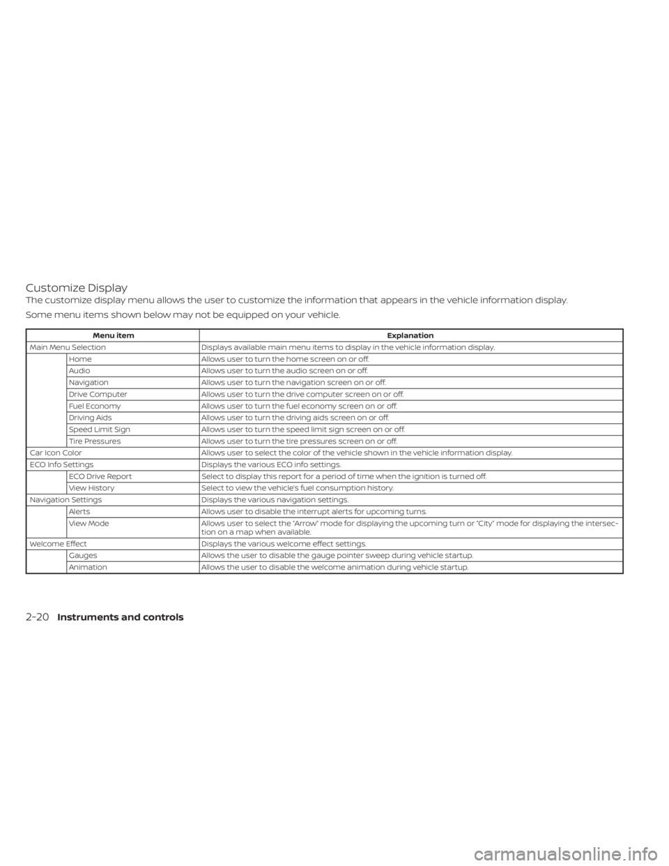
Customize Display
The customize display menu allows the user to customize the information that appears in the vehicle information display.
Some menu items shown below may not be equipped on your vehicle.
Menu itemExplanation
Main Menu Selection Displays available main menu items to display in the vehicle information display.
Home Allows user to turn the home screen on or off.
Audio Allows user to turn the audio screen on or off.
Navigation Allows user to turn the navigation screen on or off.
Drive Computer Allows user to turn the drive computer screen on or off.
Fuel Economy Allows user to turn the fuel economy screen on or off.
Driving Aids Allows user to turn the driving aids screen on or off.
Speed Limit Sign Allows user to turn the speed limit sign screen on or off.
Tire Pressures Allows user to turn the tire pressures screen on or off.
Car Icon Color Allows user to select the color of the vehicle shown in the vehicle information display.
ECO Info Settings Displays the various ECO info settings.
ECO Drive Report Select to display this report for a period of time when the ignition is turned off.
View History Select to view the vehicle’s fuel consumption history.
Navigation Settings Displays the various navigation settings.
Alerts Allows user to disable the interrupt alerts for upcoming turns.
View Mode Allows user to select the “Arrow” mode for displaying the upcoming turn or “City ” mode for displaying the intersec-
tion on a map when available.
Welcome Effect Displays the various welcome effect settings.
Gauges Allows the user to disable the gauge pointer sweep during vehicle startup.
Animation Allows the user to disable the welcome animation during vehicle startup.
2-20Instruments and controls
Page 118 of 508
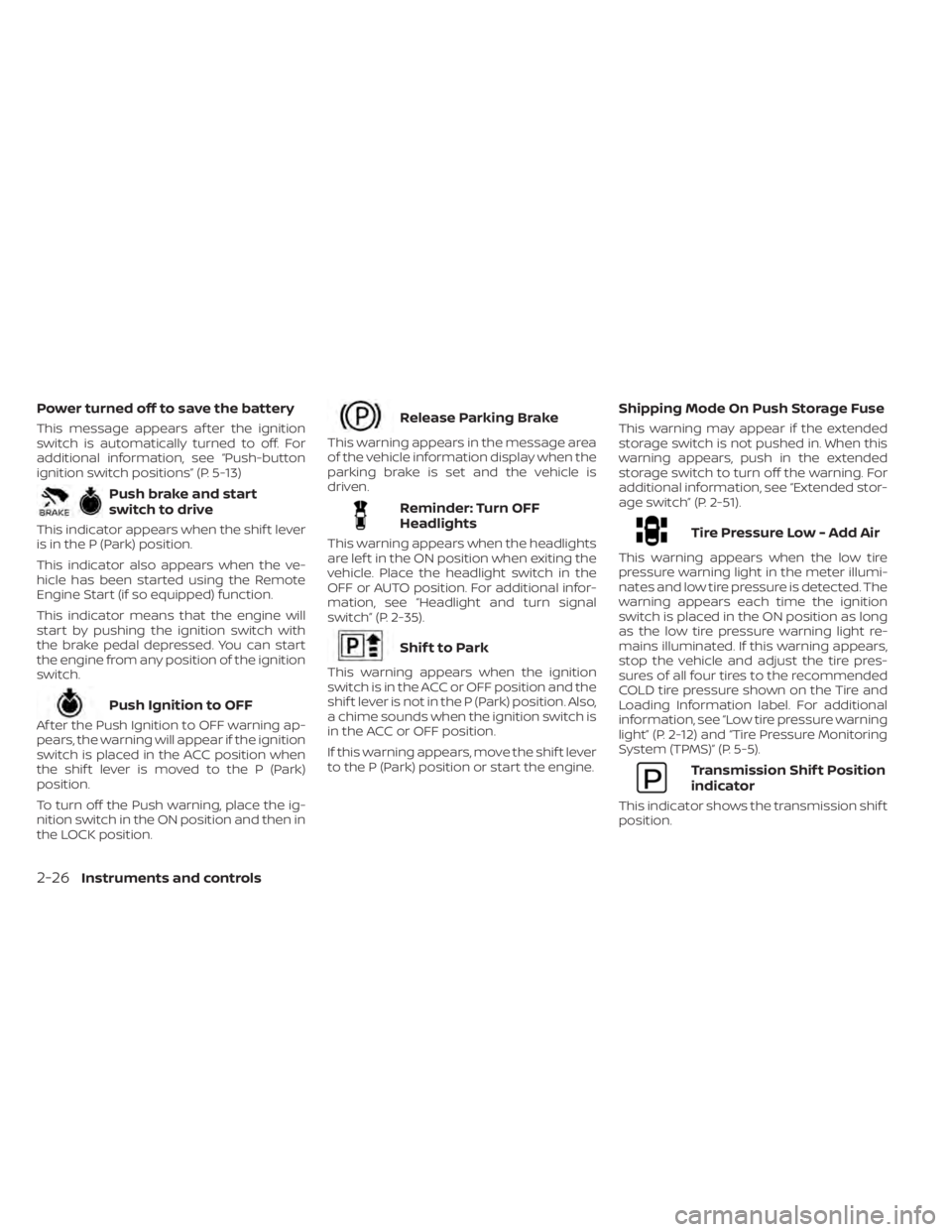
Power turned off to save the battery
This message appears af ter the ignition
switch is automatically turned to off. For
additional information, see “Push-button
ignition switch positions” (P. 5-13)
Push brake and start
switch to drive
This indicator appears when the shif t lever
is in the P (Park) position.
This indicator also appears when the ve-
hicle has been started using the Remote
Engine Start (if so equipped) function.
This indicator means that the engine will
start by pushing the ignition switch with
the brake pedal depressed. You can start
the engine from any position of the ignition
switch.
Push Ignition to OFF
Af ter the Push Ignition to OFF warning ap-
pears, the warning will appear if the ignition
switch is placed in the ACC position when
the shif t lever is moved to the P (Park)
position.
To turn off the Push warning, place the ig-
nition switch in the ON position and then in
the LOCK position.
Release Parking Brake
This warning appears in the message area
of the vehicle information display when the
parking brake is set and the vehicle is
driven.
Reminder: Turn OFF
Headlights
This warning appears when the headlights
are lef t in the ON position when exiting the
vehicle. Place the headlight switch in the
OFF or AUTO position. For additional infor-
mation, see “Headlight and turn signal
switch” (P. 2-35).
Shif t to Park
This warning appears when the ignition
switch is in the ACC or OFF position and the
shif t lever is not in the P (Park) position. Also,
a chime sounds when the ignition switch is
in the ACC or OFF position.
If this warning appears, move the shif t lever
to the P (Park) position or start the engine.
Shipping Mode On Push Storage Fuse
This warning may appear if the extended
storage switch is not pushed in. When this
warning appears, push in the extended
storage switch to turn off the warning. For
additional information, see “Extended stor-
age switch” (P. 2-51).
Tire Pressure Low - Add Air
This warning appears when the low tire
pressure warning light in the meter illumi-
nates and low tire pressure is detected. The
warning appears each time the ignition
switch is placed in the ON position as long
as the low tire pressure warning light re-
mains illuminated. If this warning appears,
stop the vehicle and adjust the tire pres-
sures of all four tires to the recommended
COLD tire pressure shown on the Tire and
Loading Information label. For additional
information, see “Low tire pressure warning
light” (P. 2-12) and “Tire Pressure Monitoring
System (TPMS)” (P. 5-5).
Transmission Shif t Position
indicator
This indicator shows the transmission shif t
position.
2-26Instruments and controls
Page 119 of 508
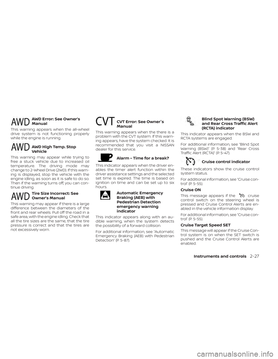
AWD Error: See Owner’s
Manual
This warning appears when the all-wheel
drive system is not functioning properly
while the engine is running.
AWD High Temp. Stop
Vehicle
This warning may appear while trying to
free a stuck vehicle due to increased oil
temperature. The driving mode may
change to 2-Wheel Drive (2WD). If this warn-
ing is displayed, stop the vehicle with the
engine idling, as soon as it is safe to do so.
Then if the warning turns off, you can con-
tinue driving.
Tire Size Incorrect: See
Owner’s Manual
This warning may appear if there is a large
difference between the diameters of the
front and rear wheels. Pull off the road in a
safe area, with the engine idling. Check that
all the tire sizes are the same, that the tire
pressure is correct and that the tires are
not excessively worn.
CVT Error: See Owner's
Manual
This warning appears when the there is a
problem with the CVT system. If this warn-
ing appears, have the system checked. It is
recommended that you visit a NISSAN
dealer for this service.
Alarm - Time for a break?
This indicator appears when the driver en-
ables the timer alert function within the
driver assistance settings and the selected
set time is expired. The time is based on
ignition on time and can be set up to six
hours.
Automatic Emergency
Braking (AEB) with
Pedestrian Detection
emergency warning
indicator
This indicator appears along with an au-
dible warning, when the system detects
the possibility of a forward collision.
For additional information, see “Automatic
Emergency Braking (AEB) with Pedestrian
Detection” (P. 5-87).
Blind Spot Warning (BSW)
and Rear Cross Traffic Alert
(RCTA) indicator
This indicator appears when the BSW and
RCTA systems are engaged.
For additional information, see “Blind Spot
Warning (BSW)” (P. 5-38) and “Rear Cross
Traffic Alert (RCTA)” (P. 5-47).
Cruise control indicator
These indicators show the cruise control
system status.
For additional information, see “Cruise con-
trol” (P. 5-55).
Cruise ON
This message appears if thecruise
control switch on the steering wheel is
pressed and Cruise Control Alerts are en-
abled in the vehicle information display.
For additional information, see “Cruise con-
trol” (P. 5-55).
Cruise Target Speed SET
This message will appear if the Cruise Con-
trol system is on when the SET switch is
pushed and the Cruise Control Alerts are
enabled.
Instruments and controls2-27
Page 159 of 508
WARNING
• Your vehicle's engine should be
turned off while programming the
HomeLink® Universal Transceiver. For
additional information, see “Push-
button ignition switch” (P. 5-13). Do
not breathe exhaust gases; they con-
tain colorless and odorless carbon
monoxide. Carbon monoxide is dan-
gerous. It can cause unconscious-
ness or death.
• Do not use the HomeLink® Universal
Transceiver with any garage door
opener that lacks safety stop and re-
verse features as required by federal
safety standards. (These standards
became effective for opener models
manufactured af ter April 1, 1982.) A
garage door opener which cannot
detect an object in the path of a clos-
ing garage door and then automati-
cally stop and reverse does not meet
current federal safety standards. Us-
ing a garage door opener without
these features increases the risk of
serious injury or death. •
During the programming procedure
your garage door or security gate will
open and close (if the transmitter is
within range). Make sure that people
or objects are clear of the garage
door, gate, etc., that you are
programming.
PROGRAMMING HOMELINK®
If you have any questions or are having
difficulty programming your HomeLink®
buttons, refer to the HomeLink® web site at:
www.homelink.com or call 1-800-355-3515.
NOTE:
Place the ignition switch in the ON or ACC
position (without starting the engine)
when programming HomeLink®. It is also
recommended that a new battery be
placed in the hand-held transmitter of
the device being programmed to
HomeLink® for quicker programming
and accurate transmission of the radio
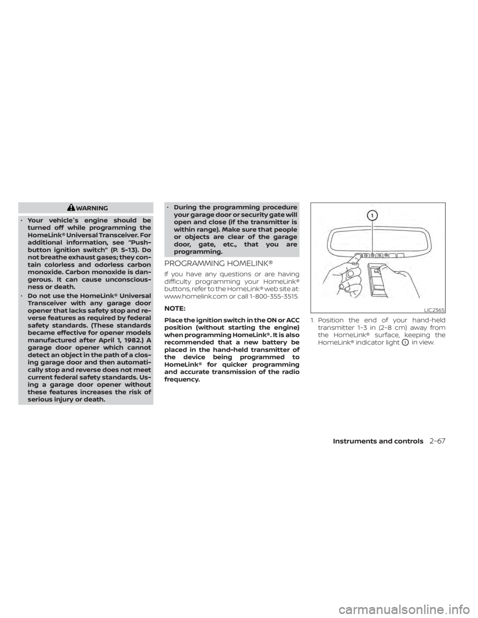
frequency. 1. Position the end of your hand-held
transmitter 1–3 in (2–8 cm) away from
the HomeLink® surface, keeping the
HomeLink® indicator light
O1in view.
LIC2365
Instruments and controls2-67
Page 162 of 508
If you have any questions or are having
difficulty programming your HomeLink®
buttons, refer to the HomeLink® web site at:
www.homelink.com or call 1-800-355-3515.
CLEARING THE PROGRAMMED
INFORMATION
The following procedure clears the pro-
grammed information from both buttons.
Individual buttons cannot be cleared. How-
ever, individual buttons can be repro-
grammed. For additional information, see
“Reprogramming a single HomeLink® but-
ton” (P. 2-70).
To clear all programming:
1. Press and hold the two outer HomeLink®buttons until the indicator light begins to
flash in approximately 10 seconds. Do
not hold for longer than 20 seconds.
2. Release both buttons.
HomeLink® is now in the programming
mode and can be programmed at any
time beginning with “Programming
HomeLink®” - Step 1 (P. 2-67).
REPROGRAMMING A SINGLE
HOMELINK® BUTTON
To reprogram a HomeLink® Universal
Transceiver button, complete the following:
1. Press and hold the desired HomeLink® button. DO NOT release the button.
2. The indicator light will begin to flash af- ter 20 seconds. Without releasing the
HomeLink® button, proceed with “Pro-
gramming HomeLink®” - Step 1 (P. 2-67).
For questions or comments, contact
HomeLink® at: www.homelink.com or
1–800–355–3515 (except Mexico).
The HomeLink® Universal Transceiver but-
ton has now been reprogrammed. The
new device can be activated by pressing
the HomeLink® button that was just pro-
grammed. This procedure will not affect
any other programmed HomeLink®
buttons.
IF YOUR VEHICLE IS STOLEN
If your vehicle is stolen, you should change
the codes of any non-rolling code device
that has been programmed into
HomeLink®. Consult the Owner's Manual of
each device or call the manufacturer or
dealer of those devices for additional
information.
When your vehicle is recovered, you will
need to reprogram the HomeLink® Uni-
versal Transceiver with your new trans-
mitter information.
FCC Notice:
For USA:
This device complies with Part 15 of the
FCC Rules. Operation is subject to the fol-
lowing two conditions: (1) This device
may not cause harmful interference, and
(2) this device must accept any interfer-
ence received, including interference
that may cause undesired operation.
NOTE:
Changes or modifications not expressly
approved by the party responsible for
compliance could void the user’s author-
ity to operate the equipment.
2-70Instruments and controls
Page 179 of 508
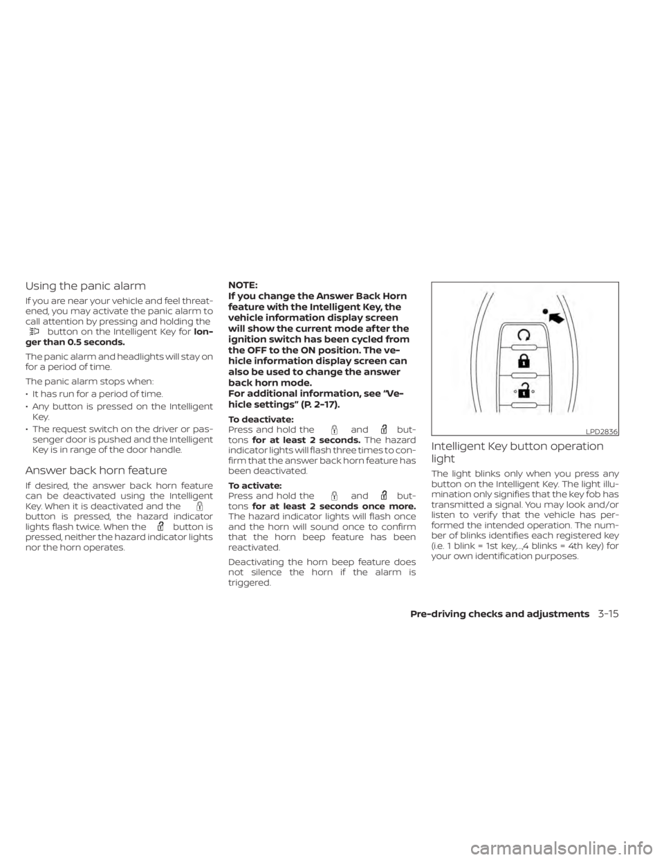
Using the panic alarm
If you are near your vehicle and feel threat-
ened, you may activate the panic alarm to
call attention by pressing and holding the
button on the Intelligent Key forlon-
ger than 0.5 seconds.
The panic alarm and headlights will stay on
for a period of time.
The panic alarm stops when:
• It has run for a period of time.
• Any button is pressed on the Intelligent Key.
• The request switch on the driver or pas- senger door is pushed and the Intelligent
Key is in range of the door handle.
Answer back horn feature
If desired, the answer back horn feature
can be deactivated using the Intelligent
Key. When it is deactivated and the
button is pressed, the hazard indicator
lights flash twice. When thebutton is
pressed, neither the hazard indicator lights
nor the horn operates.
NOTE:
If you change the Answer Back Horn
feature with the Intelligent Key, the
vehicle information display screen
will show the current mode af ter the
ignition switch has been cycled from
the OFF to the ON position. The ve-
hicle information display screen can
also be used to change the answer
back horn mode.
For additional information, see “Ve-
hicle settings” (P. 2-17).
To deactivate:
Press and hold theandbut-
tons for at least 2 seconds. The hazard
indicator lights will flash three times to con-
firm that the answer back horn feature has
been deactivated.
To activate:
Press and hold the
andbut-
tons for at least 2 seconds once more.
The hazard indicator lights will flash once
and the horn will sound once to confirm
that the horn beep feature has been
reactivated.
Deactivating the horn beep feature does
not silence the horn if the alarm is
triggered.
Intelligent Key button operation
light
The light blinks only when you press any
button on the Intelligent Key. The light illu-
mination only signifies that the key fob has
transmitted a signal. You may look and/or
listen to verif y that the vehicle has per-
formed the intended operation. The num-
ber of blinks identifies each registered key
(i.e. 1 blink = 1st key,...,4 blinks = 4th key) for
your own identification purposes.
LPD2836
Pre-driving checks and adjustments3-15
Page 182 of 508
Thebutton will be on the NISSAN
Intelligent Key® if the vehicle has Remote
Engine Start. This feature allows the engine
to start from outside the vehicle.
Vehicles with an automatic climate control
system will default to either a heating or
cooling mode depending on outside and
cabin temperatures. For additional infor-
mation, see “Remote Engine Start with In-
telligent Climate Control” (P. 4-29).
Laws in some local communities may re-
strict or prohibit the use of Remote Engine
Start, or the amount of time a parked ve-
hicle engine may idle. For example, some
laws require a person using Remote Engine Start to have the vehicle in view or may
restrict idling time except in freezing tem-
peratures. Check local regulations for any
requirements.
Other conditions may affect the function of
the Remote Engine Start feature. For addi-
tional information, see “Conditions the Re-
mote Engine Start will not work” (P. 3-20).
Other conditions can affect the perfor-
mance of the Intelligent Key transmitter.
For additional information, see “NISSAN In-
telligent Key®” (P. 3-2).
REMOTE ENGINE START
OPERATING RANGE
WARNING
• To help avoid risk of injury or death
through unintended operation of the
vehicle and/or its systems, including
entrapment in windows or inadver-
tent door lock activation, do not
leave children, people who require
the assistance of others or pets unat-
tended in your vehicle. Additionally,
the temperature inside a closed ve-
hicle on a warm day can quickly be-
come high enough to cause a signifi-
cant risk of injury or death to people
and pets. •
Do not use Remote Engine Start in
closed spaces such as a garage. Do
not breathe exhaust gases; they con-
tain colorless and odorless carbon
monoxide. Carbon monoxide is dan-
gerous. It can cause unconscious-
ness or death.
CAUTION
When the Intelligent Key battery is dis-
charged or other strong radio wave
sources are present near the operating
location, the Intelligent Key operating
range becomes narrower, and the Intel-
ligent Key may not function properly.
The Remote Engine Start function can only
be used when the Intelligent Key is within
the specified operating range from the
vehicle.
The Remote Engine Start operating range
is approximately 197 f t (60 m) from the
vehicle.
LPD2995
REMOTE ENGINE START (if so
equipped)
3-18Pre-driving checks and adjustments
Page 188 of 508
• If the lif tgate close switchOBis activated
while the cinching motor is engaged, the
cinching motor will disengage and re-
lease the latch.
• The Intelligent Key button must be held for 1 second before the lif tgate closes.
Reverse:
The power lif tgate will stop immediately
during power open or power close if the
Intelligent Key switch, instrument panel
switch, lif tgate opener switch
OAor lif tgate
close switch
OBis pushed. The power lif t-
gate will reverse direction if the Intelligent
Key switch, instrument panel switch, lif t-
gate opener switch
OAor lif tgate close
switch
OBis pushed a second time. A
chime will sound to announce the reversal.
Auto Reverse:
If an obstacle is detected during power
open or power close, a warning chime will
sound and the lif tgate will reverse direction
and return to the full open or full close po-
sition. If a second obstacle is detected, the
lif tgate motion will stop and the lif tgate will
enter manual mode.
A pinch strip is mounted on each side of
the lif tgate. If an obstacle is detected by a
pinch strip during power close, the lif tgate
will reverse direction and return to the full
open position.
NOTE:
If the pinch strip is damaged or removed,
the power close function will not
operate.
WARNING
There are some small distances imme-
diately before the closed position
which cannot be detected. Make sure
that all passengers have their hands,
etc., inside the vehicle before closing
the lif tgate.
Manual Mode:
If power operation is not available, the lif t-
gate may be operated manually. Power op-
eration may not be available if multiple ob-
stacles have been detected in a single
power cycle or if battery voltage is low.
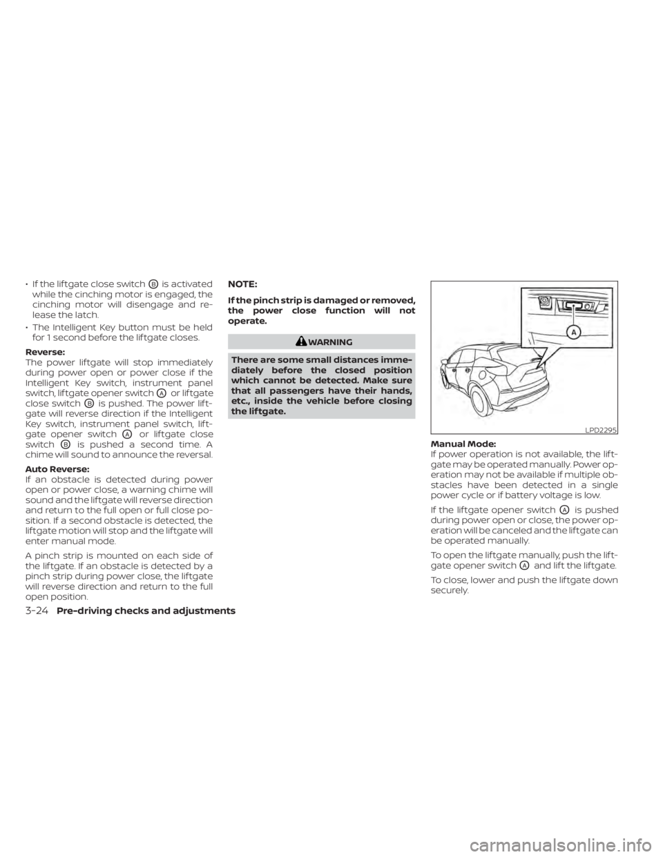
If the lif tgate opener switch
OAis pushed
during power open or close, the power op-
eration will be canceled and the lif tgate can
be operated manually.
To open the lif tgate manually, push the lif t-
gate opener switch
OAand lif t the lif tgate.
To close, lower and push the lif tgate down
securely.
LPD2295
3-24Pre-driving checks and adjustments