2021 NISSAN KICKS sensor
[x] Cancel search: sensorPage 133 of 500
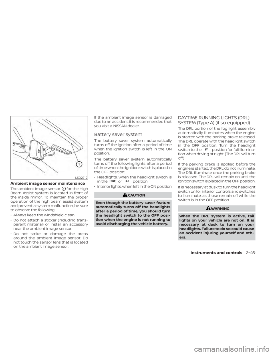
Ambient image sensor maintenance
The ambient image sensorO1for the High
Beam Assist system is located in front of
the inside mirror. To maintain the proper
operation of the high beam assist system
and prevent a system malfunction, be sure
to observe the following:
• Always keep the windshield clean.
• Do not attach a sticker (including trans- parent material) or install an accessory
near the ambient image sensor.
• Do not strike or damage the areas around the ambient image sensor. Do
not touch the sensor lens that is located
on the ambient image sensor. If the ambient image sensor is damaged
due to an accident, it is recommended that
you visit a NISSAN dealer.
Battery saver system
The battery saver system automatically
turns off the ignition af ter a period of time
when the ignition switch is lef t in the ON
position.
The battery saver system automatically
turns off the following lights af ter a period
of time when the ignition switch is placed in
the OFF position:
• Headlights, when the headlight switch is
in the
orposition
• Interior lights, when lef t in the ON position
position for full illumina-
tion when driving at night. (The DRL will turn
off.)
If the parking brake is applied before the
engine is started, the DRL do not illuminate.
The DRL illuminate once the parking brake
is released. The DRL will remain on until the
ignition switch is placed in the OFF position.
It is necessary at dusk to turn the headlight
switch on for interior controls and switches
to illuminate, as those remain off while the
switch is in the OFF position.
Page 139 of 500
WARNING
The Rear Sonar System is a conve-
nience but it is not a substitute for
proper backing. Always turn and check
that it is safe to do so before backing
up. Always back up slowly.
The RSS (if so equipped) is active when the
ignition switch is placed in the ON position
and the shif t lever is in R (Reverse). The
indicator light on the switch will turn on.
When sensors detect obstacles within 6 f t
(1.8 m) of the rear bumper, a beeping tone is
emitted. The RSS can be disabled by pushing the
OFF switch. When the system is disabled,
the indicator light on the switch will turn off.
The system will automatically reset the
next time the ignition switch is placed in
the ON position.
For additional information, refer to “Rear
Sonar System (RSS)” in the “Starting and
driving” section of this manual.
The vehicle should be driven with the VDC
system on for most driving conditions.
If the vehicle is stuck in mud or snow, the
VDC system reduces the engine output to
reduce wheel spin. The engine speed will
be reduced even if the accelerator is de-
pressed to the floor. If maximum engine
power is needed to free a stuck vehicle,
turn the VDC system off.
To turn off the VDC system, push the VDC
OFF switch. The
indicator light will
come on. The Automatic Emergency Brak-
ing (AEB) system warning light also may
come on.
LIC4227LIC4315
REAR SONAR SYSTEM (RSS) OFF
SWITCH (if so equipped) VEHICLE DYNAMIC CONTROL (VDC)
OFF SWITCH (if so equipped)
Instruments and controls2-55
Page 231 of 500
Air recirculation
Press theair recirculation button to
recirculate interior air inside the vehicle.
A/C (air conditioner) button
Start the engine, turn thefan speed
control dial to the desired position and
press the
button to turn on the air
conditioner. To turn off the air conditioner,
press the
button again.
The air conditioner cooling function op-
erates only when the engine is running.
Air flow control
Press the MODE button to manually control
air flow and select the air outlet.
— Air flows from center and side vents.
— Air flows from center and sidevents and foot outlets.
— Air flows mainly from foot outlets.— Air flows from defroster and footoutlets.
To turn system off
To turn off the heater and air conditioner,
press the ON-OFF button. Press the ON-
OFF button again, the system will turn on in
the mode which was used immediately
before the system was turned off.
Rear window and outside mirror
(if so equipped) defroster switch
For additional information, refer to “Rear
window and/or outside mirror defroster
switch (if so equipped)” in the “Instruments
and controls” section of this manual.
Heated seat switches (if so
equipped)
For additional information, refer to “Heated
seat switches” in the “Instruments and con-
trols” section of this manual.
OPERATING TIPS
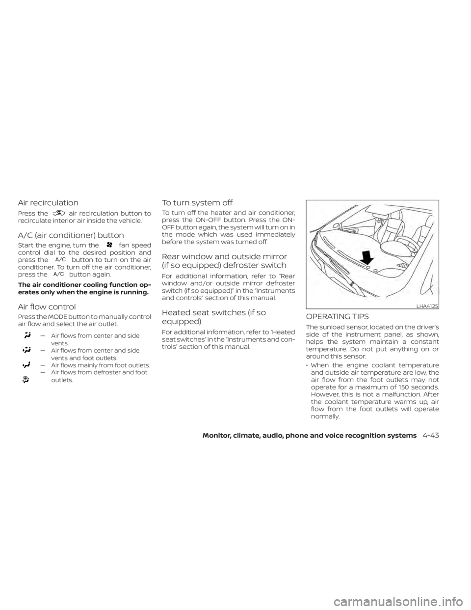
The sunload sensor, located on the driver’s
side of the instrument panel, as shown,
helps the system maintain a constant
temperature. Do not put anything on or
around this sensor.
• When the engine coolant temperatureand outside air temperature are low, the
air flow from the foot outlets may not
operate for a maximum of 150 seconds.
However, this is not a malfunction. Af ter
the coolant temperature warms up, air
flow from the foot outlets will operate
normally.
LHA4125
Page 279 of 500
WARNING
• Radio waves could adversely affect
electric medical equipment. Those
who use a pacemaker should contact
the electric medical equipment
manufacturer for the possible influ-
ences before use.
• If the low tire pressure warning light
illuminates while driving, avoid sud-
den steering maneuvers or abrupt
braking, reduce vehicle speed, pull
off the road to a safe location and
stop the vehicle as soon as possible.
Driving with under-inflated tires may
permanently damage the tires and
increase the likelihood of tire failure.
Serious vehicle damage could occur
and may lead to an accident and
could result in serious personal in-
jury. Check the tire pressure for all
four tires. Adjust the tire pressure to
the recommended COLD tire pres-
sure shown on the Tire and Loading
Information label to turn the low tire
pressure warning light off. If you have
a flat tire, replace it with a spare tire
as soon as possible. (For additional
information, refer to “Flat tire” in the
“In case of emergency ” section for
changing a flat tire.) •
When replacing a wheel without the
TPMS such as the spare tire, when a
spare tire is mounted or a wheel is
replaced, the TPMS will not function
and the low tire pressure warning
light will flash for approximately 1
minute. The light will remain on af ter
1 minute. Have your tires replaced
and/or TPMS system reset as soon as
possible. It is recommended that you
visit a NISSAN dealer for this service.
• Replacing tires with those not origi-
nally specified by NISSAN could af-
fect the proper operation of the
TPMS.
• Do not inject any tire liquid or aerosol
tire sealant into the tires, as this may
cause a malfunction of the tire pres-
sure sensors.
CAUTION
• The TPMS may not function properly
when the wheels are equipped with
tire chains or the wheels are buried in
snow. •
Do not place metalized film or any
metal parts (antenna, etc.) on the
windows. This may cause poor re-
ception of the signals from the tire
pressure sensors, and the TPMS will
not function properly.
Some devices and transmitters may tem-
porarily interfere with the operation of the
TPMS and cause the low tire pressure
warning light to illuminate.
Some examples are:
• Facilities or electric devices using similar radio frequencies are near the vehicle.
• If a transmitter set to similar frequencies is being used in or near the vehicle.
• If a computer (or similar equipment) or a DC/AC converter is being used in or near
the vehicle.
The low tire pressure warning light may
illuminate in the following cases:
• If the vehicle is equipped with a wheel and tire without TPMS.
• If the TPMS has been replaced and the ID has not been registered.
• If the wheel is not originally specified by NISSAN.
Starting and driving5-7
Page 280 of 500
FCC Notice:
For USA:
This device complies with Part 15 of the
FCC Rules. Operation is subject to the fol-
lowing two conditions: (1) This device
may not cause harmful interference, and
(2) this device must accept any interfer-
ence received, including interference
that may cause undesired operation.
NOTE:
Changes or modifications not ex-
pressly approved by the party re-
sponsible for compliance could void
the user's authority to operate the
equipment.
For Canada:
This device complies with Industry
Canada licence-exempt RSS standard(s).
Operation is subject to the following two
conditions: (1) this device may not cause
interference, and (2) this device must ac-
cept any interference, including interfer-
ence that may cause undesired opera-
tion of the device.
TPMS with Easy-Fill Tire Alert
When adding air to an under-inflated tire,
the TPMS with Easy-Fill Tire Alert provides
visual and audible signals outside the ve-
hicle to help you inflate the tires to the rec-
ommended COLD tire pressure.
Vehicle set-up
1. Park the vehicle in a safe and level place.
2. Apply the parking brake and place theshif t lever in the P (Park) position.
3. Place the ignition switch in the ON posi- tion. Do not start the engine.
Operation
1. Add air to the tire.
2. Af ter a few seconds, the hazard indica- tors will start flashing.
3. When the designated pressure is reached, the horn beeps once and the
hazard indicators stop flashing.
4. Perform the above steps for each tire. • If the tire is over-inflated more thanapproximately 4 psi (30 kPa), the horn
beeps and the hazard indicators flash
three times. To correct the pressure,
push the core of the valve stem on the
tire briefly to release pressure. When the pressure reaches the designated
pressure, the horn beeps once.
• If the hazard indicator does not flash within approximately 15 seconds af ter
starting to inflate the tire, it indicates
that the Easy-Fill Tire Alert is not oper-
ating.
• The TPMS will not activate the Easy-Fill Tire Alert under the following condi-
tions:– If there is interference from an exter- nal device or transmitter.
– The air pressure from the inflation device is not sufficient to inflate the
tire.
– There is a malfunction in the TPMS.
– There is a malfunction in the horn or hazard indicators.
– The identification code of the tire pressure sensor is not registered to
the system.
– The battery of the tire pressure sen- sor is low.
• If the Easy-Fill Tire Alert does not oper- ate due to TPMS interference, move
the vehicle about 3 f t (1 m) backward
or forward and try again.
If the Easy-Fill Tire Alert is not working, use a
tire pressure gauge.
5-8Starting and driving
Page 303 of 500
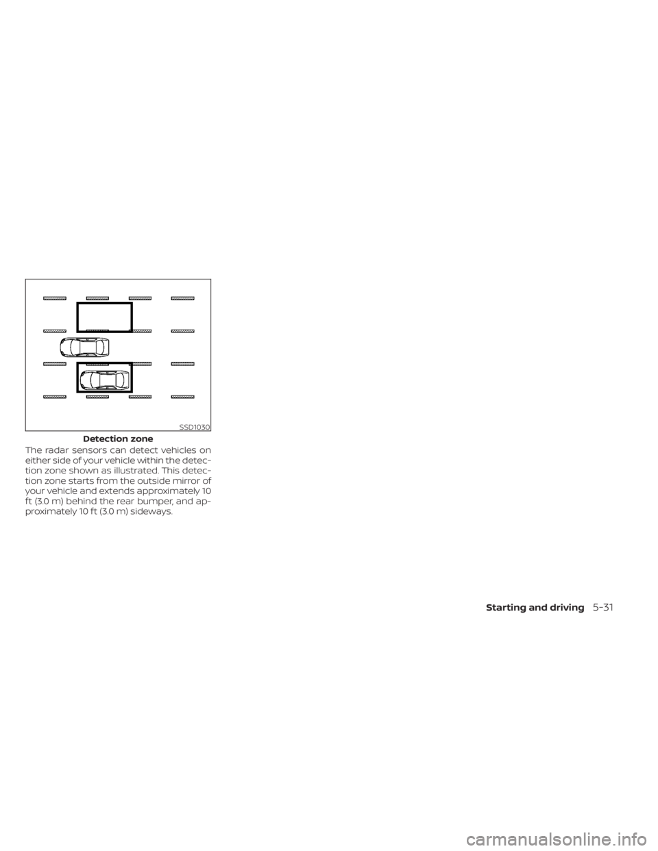
The radar sensors can detect vehicles on
either side of your vehicle within the detec-
tion zone shown as illustrated. This detec-
tion zone starts from the outside mirror of
your vehicle and extends approximately 10
f t (3.0 m) behind the rear bumper, and ap-
proximately 10 f t (3.0 m) sideways.
SSD1030
Detection zone
Starting and driving5-31
Page 305 of 500
1. Side BSW/RCTA Indicator Light
2. BSW Indicator or BSW Indicator Light
BSW SYSTEM OPERATION
The BSW system operates above approxi-
mately 20 mph (32 km/h).
If the radar sensors detect a vehicle in the
detection zone, the side BSW/RCTA indica-
tor light (1) illuminates. If the turn signal is
then activated, the system chimes (twice)
and the side BSW/RCTA indicator light
flashes. The side BSW/RCTA indicator light
continues to flash until the detected ve-
hicle leaves the detection zone.
The side BSW/RCTA indicator light illumi-
nates for a few seconds when the ignition
switch is placed in the ON position.
The brightness of the side BSW/RCTA indi-
cator light is adjusted automatically de-
pending on the brightness of the ambient
light.
If a vehicle comes into the detection zone
af ter the driver activates the turn signal,
then only the side BSW/RCTA indicator light
flashes and no chime sounds. For addi-
tional information, refer to “BSW driving
situations” in this section.
Starting and driving5-33
Page 308 of 500
–Vehicles remaining in the detec-
tion zone when you accelerate
from a stop.
– A vehicle merging into an adjacent
lane at a speed approximately the
same as your vehicle.
– A vehicle approaching rapidly
from behind.
– A vehicle which your vehicle over-
takes rapidly.
– A vehicle that passes through the
detection zone quickly.
– When overtaking several vehicles
in a row, the vehicles af ter the first
vehicle may not be detected if
they are traveling close together.
• The radar sensors’ detection zone is
designed based on a standard lane
width. When driving in a wider lane,
the radar sensors may not detect ve-
hicles in an adjacent lane. When driv-
ing in a narrow lane, the radar sen-
sors may detect vehicles driving two
lanes away. •
The radar sensors are designed to ig-
nore most stationary objects, how-
ever objects such as guardrails, walls,
foliage and parked vehicles may oc-
casionally be detected. This is a nor-
mal operation condition.
• The following conditions may reduce
the ability of the radar to detect other
vehicles:
– Severe weather
– Road spray
– Ice/frost/snow/dirt build-up on
the vehicle
• Do not attach stickers (including
transparent material), install acces-
sories or apply additional paint near
the radar sensors. These conditions
may reduce the ability of the radar to
detect other vehicles.
• Excessive noise (for example, audio
system volume, open vehicle win-
dow) will interfere with the chime
sound, and it may not be heard.
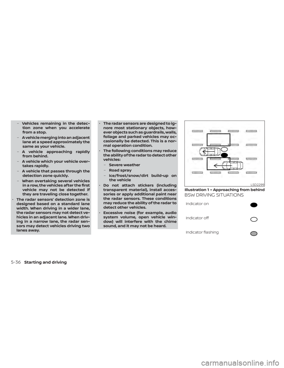
BSW DRIVING SITUATIONS
Indicator on
Indicator off
Indicator flashing
LSD2299
Illustration 1 – Approaching from behind