2021 NISSAN KICKS steering wheel
[x] Cancel search: steering wheelPage 100 of 500
WARNING
• Radio waves could adversely affect
electric medical equipment. Those
who use a pacemaker should contact
the electric medical equipment
manufacturer for the possible influ-
ences before use.
• If the light does not illuminate with
the ignition switch placed in the ON
position, have the vehicle checked as
soon as possible. It is recommended
that you visit a NISSAN dealer for this
service.
• If the light illuminates while driving,
avoid sudden steering maneuvers or
abrupt braking, reduce vehicle
speed, pull off the road to a safe loca-
tion and stop the vehicle as soon as
possible. Driving with under-inflated
tires may permanently damage the
tires and increase the likelihood of
tire failure. Serious vehicle damage
could occur and may lead to an acci-
dent and could result in serious per-
sonal injury or death. Check the tire
pressure for all four tires. Adjust the
tire pressure to the recommended COLD tire pressure show on the Tire
and Loading Information label lo-
cated in the driver’s door opening to
turn the low tire pressure warning
light off. If the light still illuminates
while driving af ter adjusting the tire
pressure, a tire may be flat or the
TPMS may be malfunctioning. If you
have a flat tire, replace it with a spare
tire as soon as possible. If no tire is
flat and all tires are properly inflated,
have the vehicle checked. It is recom-
mended that you visit a NISSAN
dealer for this service.
• When replacing a wheel without the
TPMS such as the spare tire, the TPMS
will not function and the low tire
pressure warning light will flash for
approximately 1 minute. The light will
remain on af ter 1 minute. Have your
tires replaced and/or TPMS system
reset as soon as possible. It is recom-
mended that you visit a NISSAN
dealer for these services.
• Replacing tires with those not origi-
nally specified by NISSAN could af-
fect the proper operation of the
TPMS.CAUTION
• The TPMS is not a substitute for the
regular tire pressure check. Be sure
to check the tire pressure regularly.
• If the vehicle is being driven at
speeds of less than 16 mph (25 km/h),
the TPMS may not operate correctly.
• Be sure to install the specified size of
tires to the four wheels correctly.
Master warning light (if so
equipped)
This light illuminates when various vehicle
information display warnings appear.
•Nokey
• I-Key system warning
• Low washer fluid
• Door open
• Parking brake release
2-16Instruments and controls
Page 119 of 500
• Blind Spot Warning (BSW)
• Rear Cross Traffic Alert (RCTA)
If one or more of these warning appears,
have the system checked. It is recom-
mended that you visit a NISSAN dealer for
this service.
Shipping Mode On Push Storage Fuse
This warning may appear if the extended
storage switch is not pushed in. When this
warning appears, push in the extended
storage switch to turn off the warning. For
additional information, refer to “Extended
storage switch” in this section.
CVT Error: See Owner's Manual
This warning illuminates when there is a
problem with the CVT system. If this warn-
ing comes on, have the system checked. It
is recommended that you visit a NISSAN
dealer for this service.
Steering lock release malfunction
indicator (if so equipped)
This indicator appears when the steering
lock cannot be released.
If this indicator appears, push the ignition
switch while lightly turning the steering
wheel right and lef t.
Illumination indicator
This indicator shows the illumination ad-
justment of the instrument panel. For addi-
tional information, refer to “Instrument
brightness control” in this section.
Transmission Shif t Position indicator
(if so equipped)
This indicator shows the transmission shif t
position.
High Coolant Temp: See Owner’s
Manual
This warning appears when the tempera-
ture of the engine coolant is too high. Stop
the vehicle in a safe location as soon as
possible. Avoid quick starting or abrupt ac-
celeration. When the warning turns off, the
vehicle can be driven.
If the warning appears again soon af ter it
turns off, have the vehicle checked. It is rec-
ommended that you visit a NISSAN dealer
for this service.
Outside Temperature Display
The outside temperature display appears
in the center region of the vehicle informa-
tion display.
Low Outside Temperature
This warning appears if the outside tem-
perature is below 37°F (3°C). The tempera-
ture can be changed to display in Celsius or
Fahrenheit. For additional information, re-
fer to “Settings” in this section.
Oil and Filter
This indicator appears when the customer
set distance comes for changing the en-
gine oil and filter. You can set or reset the
distance for checking or replacing these
items. For scheduled maintenance items
and intervals, refer to the “Maintenance and
schedules” section of this manual.
Tire
This indicator appears when the customer
set distance is reached for replacing tires.
You can set or reset the distance for replac-
ing tires.
Instruments and controls2-35
Page 120 of 500
WARNING
The tire replacement indicator is not a
substitute for regular tire checks, in-
cluding tire pressure checks. For addi-
tional information, refer to “Changing
wheels and tires” in the “Do-it-yourself ”
section of this manual. Many factors in-
cluding tire inflation, alignment, driving
habits and road conditions affect tire
wear and when tires should be re-
placed. Setting the tire replacement in-
dicator for a certain driving distance
does not mean your tires will last that
long. Use the tire replacement indicator
as a guide only and always perform
regular tire checks. Failure to perform
regular tire checks, including tire pres-
sure checks could result in tire failure.
Serious vehicle damage could occur
and may lead to a collision, which could
result in serious personal injury or
death.
Other
This indicator appears when the customer
set distance is reached for checking or re-
placing maintenance items other than the
engine oil, oil filter and tires. Other mainte-
nance items can include such things as air filter or tire rotation. The distance for
checking or replacing the items can be set
or reset.
Front Radar Obstruction (if so
equipped)
This warning appears when there is a radar
obstruction detected. For additional infor-
mation, refer to “Automatic Emergency
Braking (AEB)” and “Automatic Emergency
Braking (AEB) with Pedestrian Detection” in
the “Starting and driving” section of this
manual.
Side Radar Obstruction (if so
equipped)
This message appears when the Blind
Spot Warning (BSW) or Rear Cross Traffic
Alert (RCTA) systems become unavailable
because a radar blockage is detected. For
additional information, refer to “Blind Spot
Warning (BSW)” or “Rear Cross Traffic Alert
(RCTA)” in the “Starting and driving” section
of this manual.
Drive Sport mode indicator (if so
equipped)
A small “S” appears to the right of the Trans-
mission Shif t Position indicator in the ve-
hicle information display when the Drive
Sport mode is engaged.Activate the Drive Sport mode by pressing
the switch on the shif t lever while the shif t
lever is in the D (Drive) position.
For additional information, refer to “Driving
the vehicle” in the “Starting and driving” sec-
tion of this manual.
Rear Door Alert is activated (if so
equipped)
When the system is enabled, this message
appears when the Rear Door Alert system
is active and can remind the driver to check
the back seat.
• Using the steering wheel switch, a driver
can select “Dismiss Message” to clear the
display for a period of time. If no selection
is made, this message automatically
turns off af ter a period of time.
• Using the steering wheel switch, a driver can select “Disable Alert” to disable the
horn alert for the remainder of the cur-
rent trip.
2-36Instruments and controls
Page 136 of 500
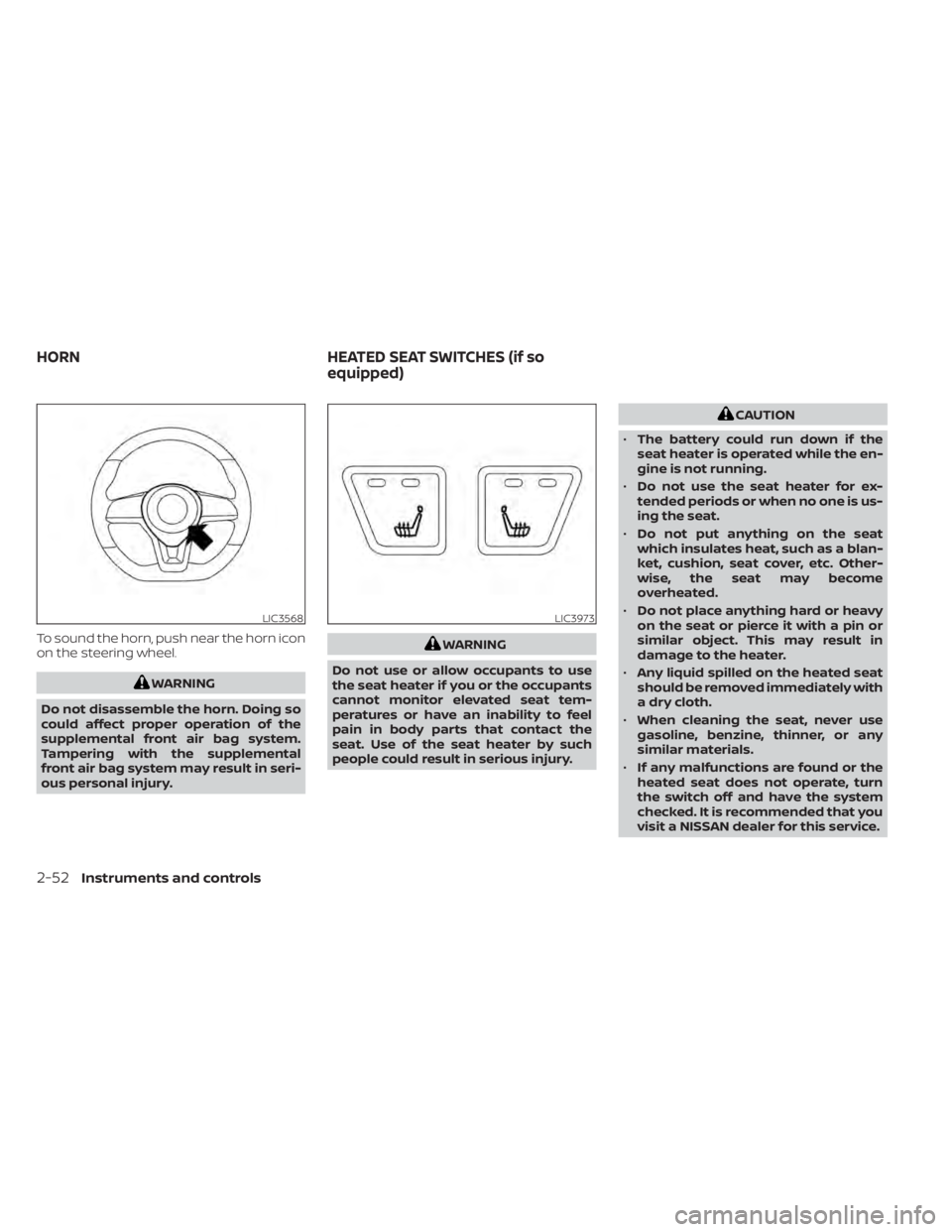
To sound the horn, push near the horn icon
on the steering wheel.WARNING
Do not use or allow occupants to use
the seat heater if you or the occupants
cannot monitor elevated seat tem-
peratures or have an inability to feel
pain in body parts that contact the
seat. Use of the seat heater by such
people could result in serious injury.
CAUTION
• The battery could run down if the
seat heater is operated while the en-
gine is not running.
• Do not use the seat heater for ex-
tended periods or when no one is us-
ing the seat.
• Do not put anything on the seat
which insulates heat, such as a blan-
ket, cushion, seat cover, etc. Other-
wise, the seat may become
overheated.
• Do not place anything hard or heavy
on the seat or pierce it with a pin or
similar object. This may result in
damage to the heater.
• Any liquid spilled on the heated seat
should be removed immediately with
a dry cloth.
• When cleaning the seat, never use
gasoline, benzine, thinner, or any
similar materials.
• If any malfunctions are found or the
heated seat does not operate, turn
the switch off and have the system
checked. It is recommended that you
visit a NISSAN dealer for this service.
LIC3973
HORN HEATED SEAT SWITCHES (if so
equipped)
Page 184 of 500
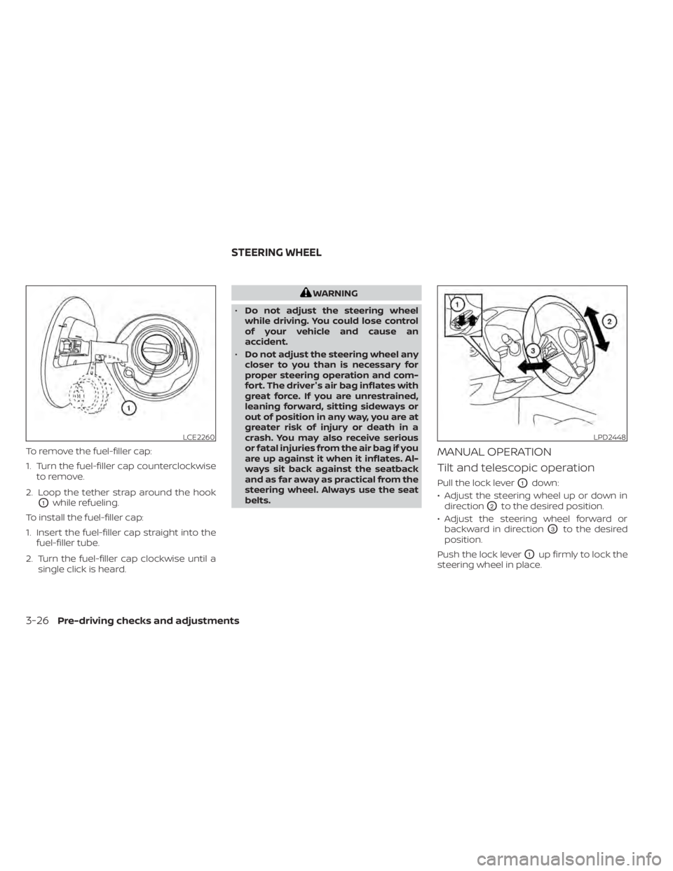
To remove the fuel-filler cap:
1. Turn the fuel-filler cap counterclockwiseto remove.
2. Loop the tether strap around the hook
O1while refueling.
To install the fuel-filler cap:
1. Insert the fuel-filler cap straight into the fuel-filler tube.
2. Turn the fuel-filler cap clockwise until a single click is heard.
LCE2260LPD2448
STEERING WHEEL
Page 199 of 500
HOW TO READ THE DISPLAYED
LINES
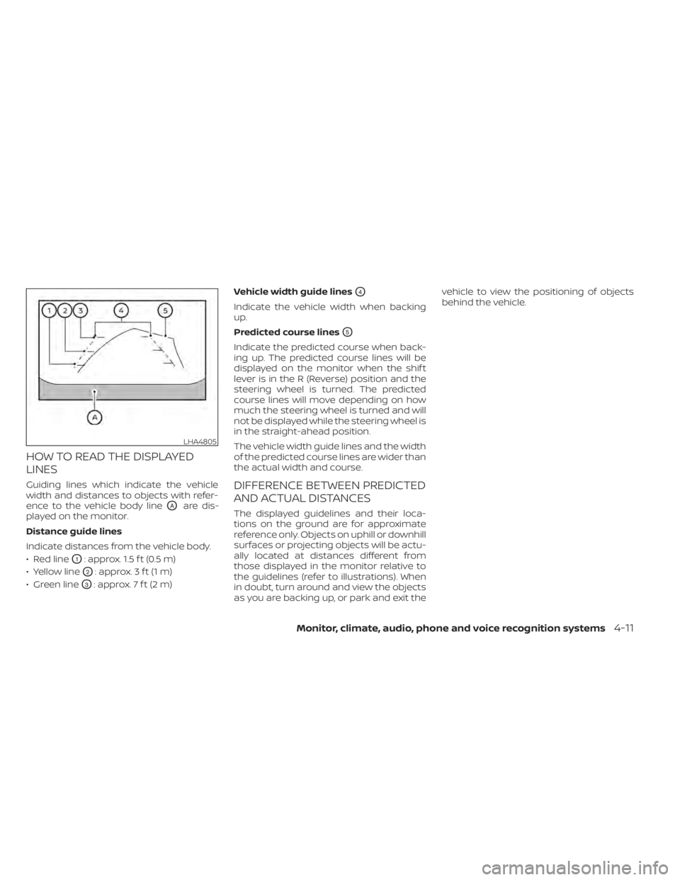
Guiding lines which indicate the vehicle
width and distances to objects with refer-
ence to the vehicle body line
OAare dis-
played on the monitor.
Distance guide lines
Indicate distances from the vehicle body.
• Red line
O1: approx. 1.5 f t (0.5 m)
• Yellow line
O2: approx. 3 f t (1 m)
• Green line
O3: approx. 7 f t (2 m) Vehicle width guide lines
O4
Indicate the vehicle width when backing
up.
Predicted course lines
O5
Indicate the predicted course when back-
ing up. The predicted course lines will be
displayed on the monitor when the shif t
lever is in the R (Reverse) position and the
steering wheel is turned. The predicted
course lines will move depending on how
much the steering wheel is turned and will
not be displayed while the steering wheel is
in the straight-ahead position.
The vehicle width guide lines and the width
of the predicted course lines are wider than
the actual width and course.
DIFFERENCE BETWEEN PREDICTED
AND ACTUAL DISTANCES
The displayed guidelines and their loca-
tions on the ground are for approximate
reference only. Objects on uphill or downhill
surfaces or projecting objects will be actu-
ally located at distances different from
those displayed in the monitor relative to
the guidelines (refer to illustrations). When
in doubt, turn around and view the objects
as you are backing up, or park and exit the vehicle to view the positioning of objects
behind the vehicle.
LHA4805
Page 202 of 500
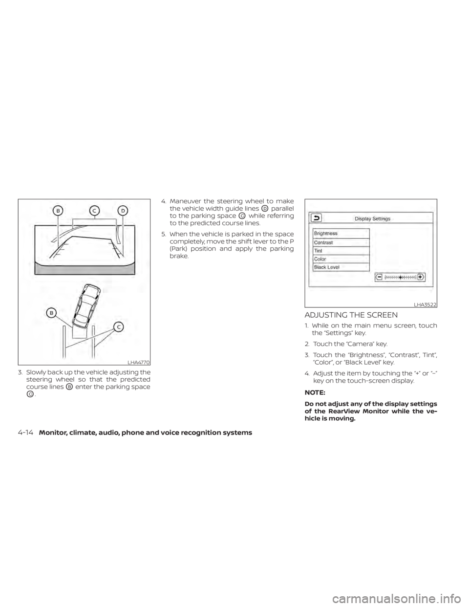
3. Slowly back up the vehicle adjusting thesteering wheel so that the predicted
course lines
OBenter the parking space
OC. 4. Maneuver the steering wheel to make
the vehicle width guide lines
ODparallel
to the parking space
OCwhile referring
to the predicted course lines.
5. When the vehicle is parked in the space completely, move the shif t lever to the P
(Park) position and apply the parking
brake.
ADJUSTING THE SCREEN
1. While on the main menu screen, touchthe “Settings” key.
2. Touch the “Camera” key.
3. Touch the “Brightness”, “Contrast”, Tint”, “Color”, or “Black Level” key.
4. Adjust the item by touching the “+” or “–” key on the touch-screen display.
NOTE:
Do not adjust any of the display settings
of the RearView Monitor while the ve-
hicle is moving.
LHA3522
4-14Monitor, climate, audio, phone and voice recognition systems
Page 208 of 500
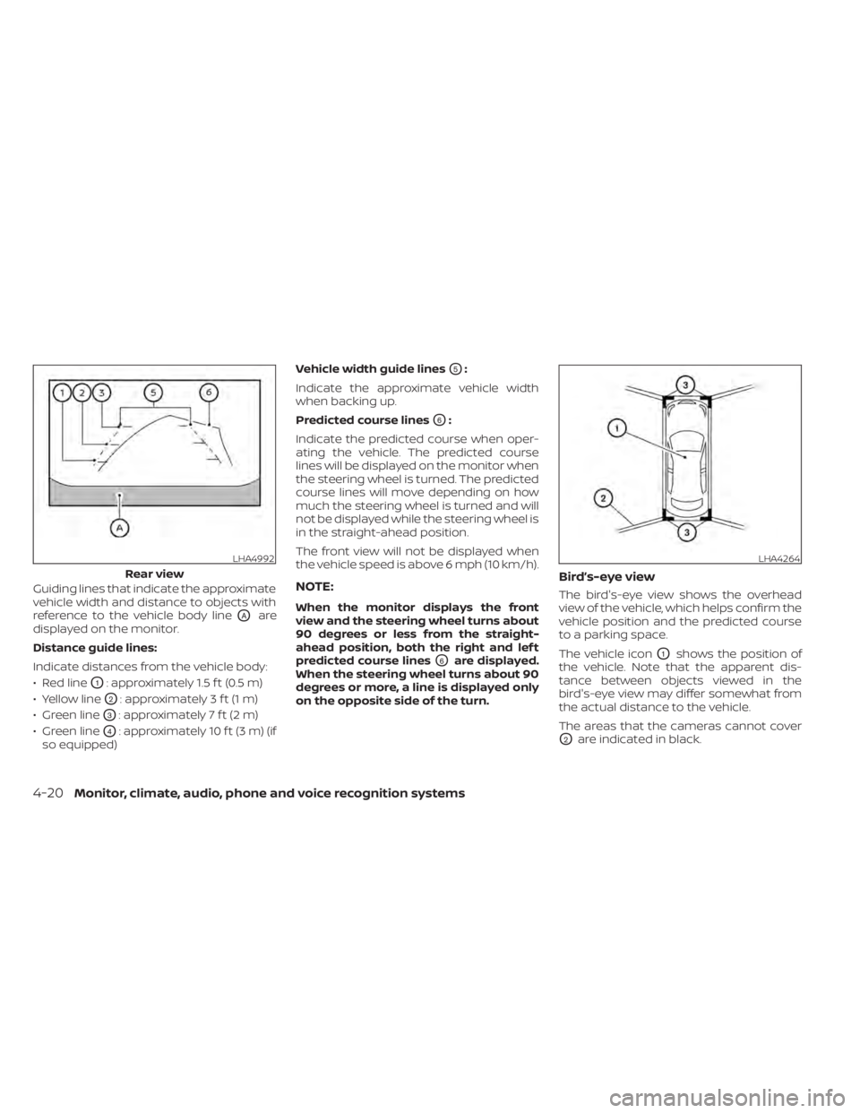
Guiding lines that indicate the approximate
vehicle width and distance to objects with
reference to the vehicle body line
OAare
displayed on the monitor.
Distance guide lines:
Indicate distances from the vehicle body:
• Red line
O1: approximately 1.5 f t (0.5 m)
• Yellow line
O2: approximately 3 f t (1 m)
• Green line
O3: approximately 7 f t (2 m)
• Green line
O4: approximately 10 f t (3 m) (if
so equipped) Vehicle width guide lines
O5:
Indicate the approximate vehicle width
when backing up.
Predicted course lines
O6:
Indicate the predicted course when oper-
ating the vehicle. The predicted course
lines will be displayed on the monitor when
the steering wheel is turned. The predicted
course lines will move depending on how
much the steering wheel is turned and will
not be displayed while the steering wheel is
in the straight-ahead position.
The front view will not be displayed when
the vehicle speed is above 6 mph (10 km/h).
NOTE:
When the monitor displays the front
view and the steering wheel turns about
90 degrees or less from the straight-
ahead position, both the right and lef t
predicted course lines
O6are displayed.
When the steering wheel turns about 90
degrees or more, a line is displayed only
on the opposite side of the turn.
Bird’s-eye view
The bird's-eye view shows the overhead
view of the vehicle, which helps confirm the
vehicle position and the predicted course
to a parking space.
The vehicle icon
O1shows the position of
the vehicle. Note that the apparent dis-
tance between objects viewed in the
bird's-eye view may differ somewhat from
the actual distance to the vehicle.
The areas that the cameras cannot cover
O2are indicated in black.
LHA4992
Rear view
4-20Monitor, climate, audio, phone and voice recognition systems