Page 354 of 500
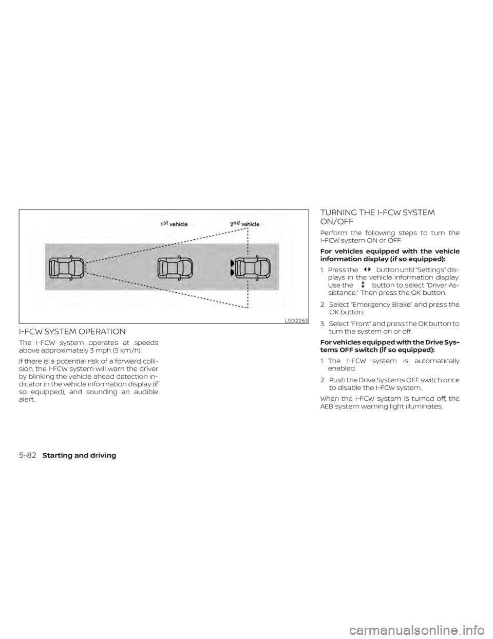
I-FCW SYSTEM OPERATION
The I-FCW system operates at speeds
above approximately 3 mph (5 km/h).
If there is a potential risk of a forward colli-
sion, the I-FCW system will warn the driver
by blinking the vehicle ahead detection in-
dicator in the vehicle information display (if
so equipped), and sounding an audible
alert.
TURNING THE I-FCW SYSTEM
ON/OFF
Perform the following steps to turn the
I-FCW system ON or OFF.
For vehicles equipped with the vehicle
information display (if so equipped):
1. Press the
button until “Settings” dis-
plays in the vehicle information display.
Use the
button to select “Driver As-
sistance.” Then press the OK button.
2. Select “Emergency Brake” and press the OK button.
3. Select “Front” and press the OK button to turn the system on or off.
For vehicles equipped with the Drive Sys-
tems OFF switch (if so equipped):
1. The I-FCW system is automatically enabled.
2. Push the Drive Systems OFF switch once to disable the I-FCW system.
When the I-FCW system is turned off, the
AEB system warning light illuminates.
LSD2263
5-82Starting and driving
Page 356 of 500
NOTE:
• The I-FCW system will be automaticallyturned on when the engine is re-
started.
• The I-FCW system is integrated into the AEB system (if so equipped). There is
not a separate selection in the vehicle
information display for the I-FCW sys-
tem. When the AEB system is turned
off, the I-FCW system is also turned off.
I-FCW SYSTEM LIMITATIONS
Page 361 of 500
The AEB system warning light (orange) will
illuminate and the “Front Radar Obstruc-
tion” warning message will appear in the
vehicle information display (if so equipped).
When driving on roads with limited road
structures or buildings (for example, long
bridges, deserts, snow fields, driving next to
long walls), the system may illuminate the
system warning light (orange) and display
the “Front Radar Obstruction” message in
the vehicle information display (if so
equipped).
Action to take
If the warning light (orange) comes on, stop
the vehicle in a safe place, place the shif t
lever in the P (Park) position and turn the
engine off. Clean the radar cover on the
lower grille with a sof t cloth, and restart the
engine. If the warning light continues to
illuminate, have the I-FCW system checked.
It is recommended that you visit a NISSAN
dealer for this service.
NOTE:
If the AEB system stops working, the
I-FCW system will also stop working.
Page 362 of 500
SYSTEM MALFUNCTION
If the I-FCW system malfunctions, it will be
turned off automatically, a chime will
sound, the AEB system warning light (or-
ange) will illuminate and the warning mes-
sage [Malfunction] will appear in the vehicle
information display (if so equipped).
Action to take
If the warning light (orange) comes on, stop
the vehicle in a safe location, turn the en-
gine off and restart the engine. If the warn-
ing light continues to illuminate, have the
I-FCW system checked. It is recommended
that you visit a NISSAN dealer for this ser-
vice.
SYSTEM MAINTENANCE
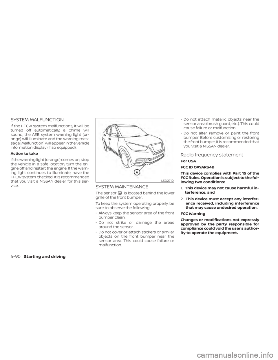
The sensorOAis located behind the lower
grille of the front bumper.
To keep the system operating properly, be
sure to observe the following:
• Always keep the sensor area of the front bumper clean.
• Do not strike or damage the areas around the sensor.
• Do not cover or attach stickers or similar objects on the front bumper near the
sensor area. This could cause failure or
malfunction. • Do not attach metallic objects near the
sensor area (brush guard, etc.). This could
cause failure or malfunction.
• Do not alter, remove or paint the front bumper. Before customizing or restoring
the front bumper, it is recommended that
you visit a NISSAN dealer.
Radio frequency statement
For USA
FCC ID OAYARS4B
This device complies with Part 15 of the
FCC Rules. Operation is subject to the fol-
lowing two conditions:
1. This device may not cause harmful in-
terference, and
2. This device must accept any interfer-
ence received, including interference
that may cause undesired operation.
FCC Warning
Changes or modifications not expressly
approved by the party responsible for
compliance could void the user’s author-
ity to operate the equipment.
5-90Starting and driving
Page 364 of 500
WARNING
Failure to follow the warnings and in-
structions for proper use of the I-DA
system could result in serious injury or
death.
• The I–DA system is only a warning to
inform the driver of a potential lack
of driver attention or drowsiness. It
will not steer the vehicle or prevent
loss of control.
• The I–DA system does not detect and
provide an alert of the driver’s lack of
attention or fatigue in every
situation.
• It is the driver’s responsibility to:
• stay alert,
• drive safely,
• keep the vehicle in the traveling
lane,
• be in control of the vehicle at all
times,
• avoid driving when tired,
• avoid distractions (texting, etc). The I–DA system helps alert the driver if the
system detects a lack of attention or driv-
ing fatigue.
The system monitors driving style and
steering behavior over a period of time,
and it detects changes from the normal
pattern. If the system detects that driver
attention is decreasing over a period of
time, the system uses audible and visual
warnings to suggest that the driver take a
break.
INTELLIGENT DRIVER ALERTNESS
SYSTEM OPERATION
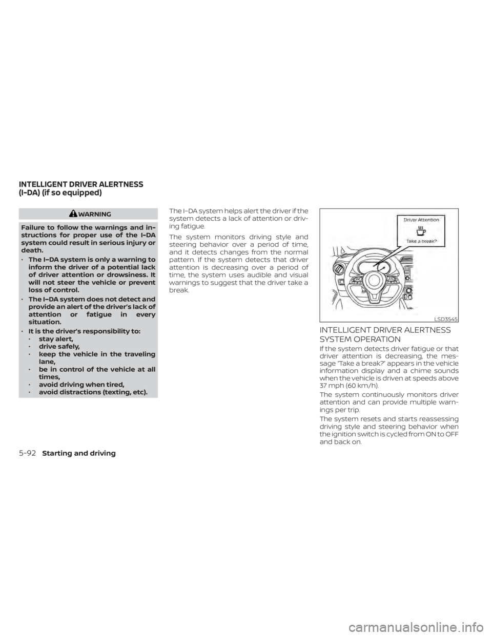
If the system detects driver fatigue or that
driver attention is decreasing, the mes-
sage “Take a break?” appears in the vehicle
information display and a chime sounds
when the vehicle is driven at speeds above
37 mph (60 km/h).
The system continuously monitors driver
attention and can provide multiple warn-
ings per trip.
The system resets and starts reassessing
driving style and steering behavior when
the ignition switch is cycled from ON to OFF
and back on.
LSD3545
INTELLIGENT DRIVER ALERTNESS
(I-DA) (if so equipped)
Page 365 of 500
HOW TO ENABLE/DISABLE THE
INTELLIGENT DRIVER ALERTNESS
(I-DA) SYSTEM
Perform the following steps to enable or
disable the I–DA system.
1. Press the
button until “Settings” dis-
plays in the vehicle information display
and press the OK button. Use the
button to select “Driver Assistance.” Then
press the OK button.
2. Select “Driver Attention Alert” and press the OK button.
NOTE:
The setting will be retained even if
the engine is restarted.
Page 373 of 500
When the VDC system operates, theindicator light in the instrument panel
flashes so note the following:
• The road may be slippery or the systemmay determine some action is required
to help keep the vehicle on the steered
path.
• You may feel a pulsation in the brake pedal and hear a noise or vibration from
under the hood. This is normal and indi-
cates that the VDC system is working
properly.
• Adjust your speed and driving to the road conditions.
For additional information, refer to “Slip in-
dicator light” and ”Vehicle Dynamic Control
(VDC) OFF indicator light” in the ”Instru-
ments and controls” section of this manual.
If a malfunction occurs in the system, the
indicator light comes on in the instru-
ment panel. The VDC system automatically
turns off when these indicator lights are on.
The VDC OFF switch, or the vehicle infor-
mation display, is used to turn off the VDC
system. The
indicator light and the
Automatic Emergency Braking (AEB) sys-
tem warning light illuminate to indicate the
VDC system is off. When the VDC OFF switch, or the vehicle
information display, is used to turn off the
system, the VDC system still operates to
prevent one drive wheel from slipping by
transferring power to a non-slipping drive
wheel. The
indicator light flashes if this
occurs. All other VDC functions are off and
the
indicator light will not flash.
The VDC system is automatically reset to
on when the ignition switch is placed in the
OFF position then back to the ON position.
The computer has a built-in diagnostic fea-
ture that tests the system each time you
start the engine and move the vehicle for-
ward or in reverse at a slow speed. When
the self-test occurs, you may hear a clunk
noise and/or feel a pulsation in the brake
pedal. This is normal and is not an indica-
tion of a malfunction.
indicator light may flash
or illuminate.
• If brake related parts such as brake
pads, rotors and calipers are not
NISSAN recommended or are ex-
tremely deteriorated, the VDC sys-
tem may not operate properly and
the
indicator light may
illuminate.
Starting and driving5-101
Page 375 of 500
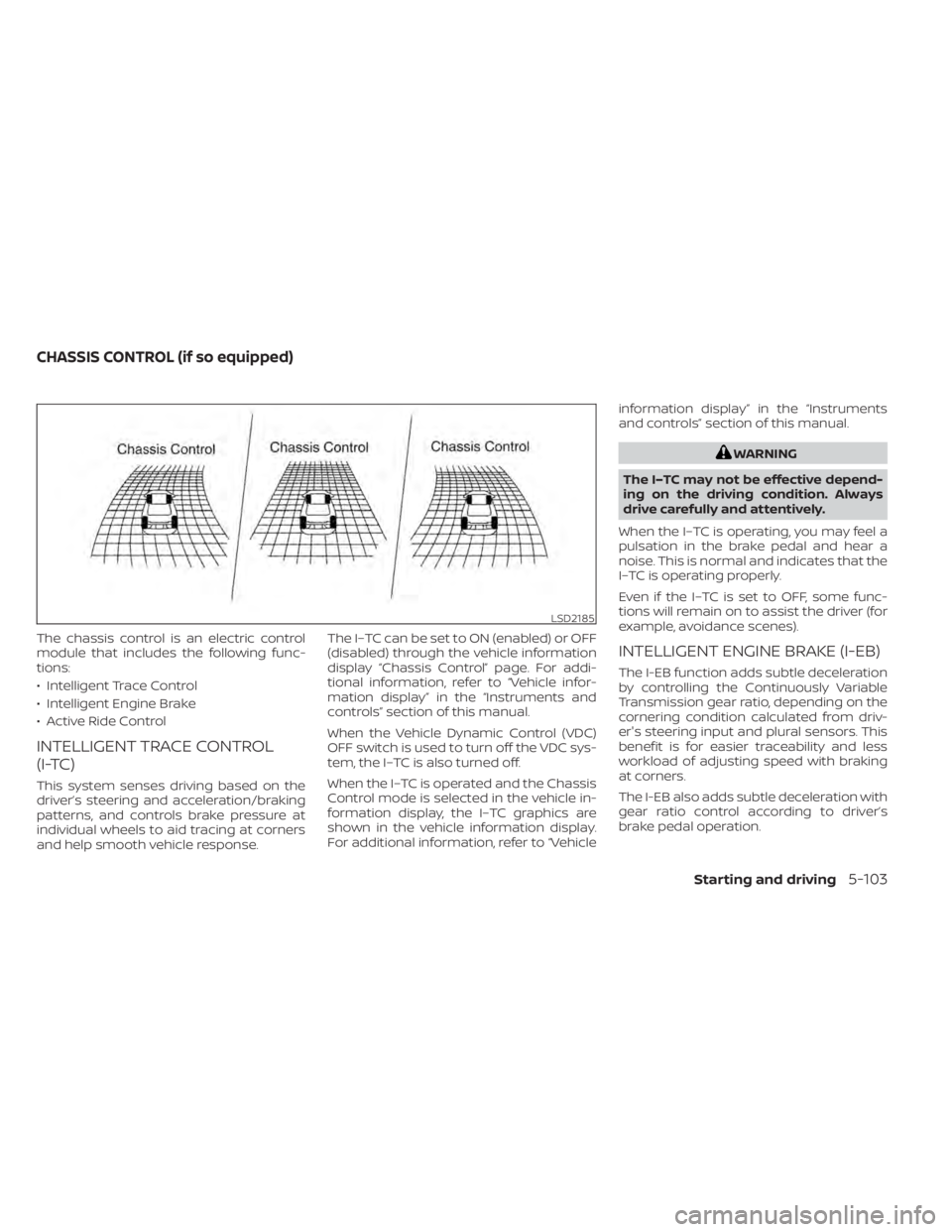
The chassis control is an electric control
module that includes the following func-
tions:
• Intelligent Trace Control
• Intelligent Engine Brake
• Active Ride Control
INTELLIGENT TRACE CONTROL
(I-TC)
This system senses driving based on the
driver’s steering and acceleration/braking
patterns, and controls brake pressure at
individual wheels to aid tracing at corners
and help smooth vehicle response.The I–TC can be set to ON (enabled) or OFF
(disabled) through the vehicle information
display “Chassis Control” page. For addi-
tional information, refer to “Vehicle infor-
mation display” in the “Instruments and
controls” section of this manual.
When the Vehicle Dynamic Control (VDC)
OFF switch is used to turn off the VDC sys-
tem, the I–TC is also turned off.
When the I–TC is operated and the Chassis
Control mode is selected in the vehicle in-
formation display, the I–TC graphics are
shown in the vehicle information display.
For additional information, refer to “Vehicleinformation display” in the “Instruments
and controls” section of this manual.
LSD2185
CHASSIS CONTROL (if so equipped)
Starting and driving5-103