Page 356 of 492

Getting the spare tire and tools
(Crew Cab models)
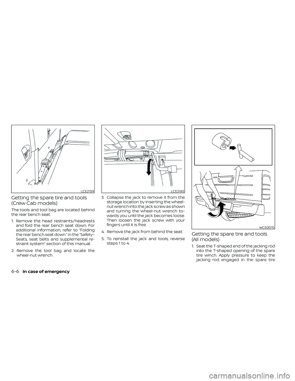
The tools and tool bag are located behind
the rear bench seat.
1. Remove the head restraints/headrestsand fold the rear bench seat down. For
additional information, refer to “Folding
the rear bench seat down ” in the “Safety–
Seats, seat belts and supplemental re-
straint system” section of this manual.
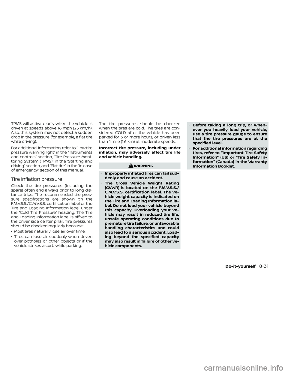
2. Remove the tool bag and locate the wheel-nut wrench. 3. Collapse the jack to remove it from the
storage location by inserting the wheel-
nut wrench into the jack screw as shown
and turning the wheel-nut wrench to-
wards you until the jack becomes loose.
Then loosen the jack screw with your
fingers until it is free.
4. Remove the jack from behind the seat.
5. To reinstall the jack and tools, reverse steps 1 to 4.
Getting the spare tire and tools
(All models)
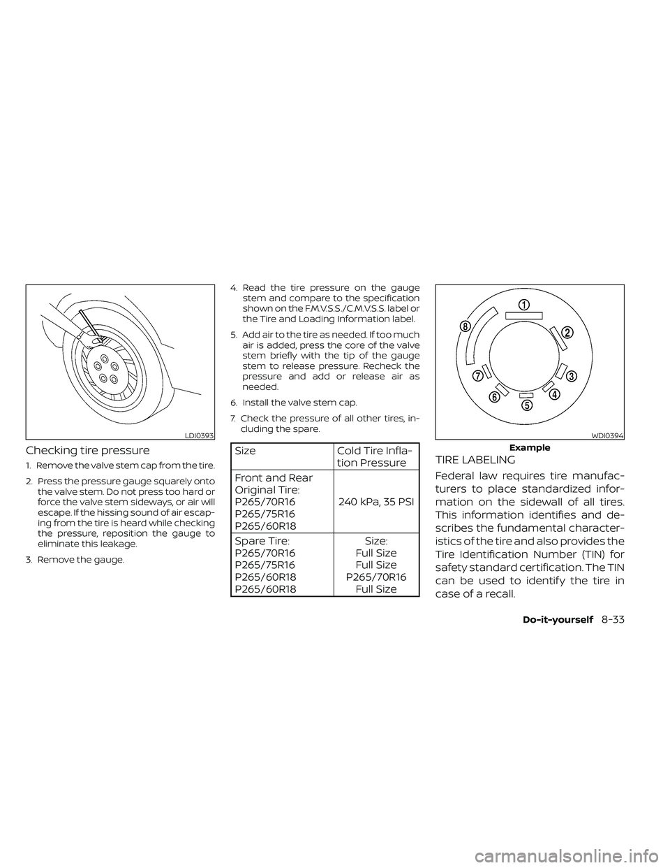
1. Seat the T-shaped end of the jacking rodinto the T-shaped opening of the spare
tire winch. Apply pressure to keep the
jacking rod engaged in the spare tire
LCE2159LCE2165
WCE0070
6-6In case of emergency
Page 357 of 492
winch and turn the jacking rod counter-
clockwise to lower the spare tire.
2. Once the spare tire is completely low- ered, reach under the vehicle, remove
the retainer chain, and carefully slide the
tire from under the rear of the vehicle.
3. To reinstall the wheel, remove the centercap and insert the tire chain through the
wheel. Be sure the rubber spacer is cen-
tered on the wheel before lif ting. Use the
assembled jacking rod to slowly rotate
the winch clockwise to raise the wheel
to the vehicle.
NOTE:
Inspect the spacer every six years and
replace as necessary. It is recommended
that you visit a NISSAN dealer for this
service.
CAUTION
• Be sure to center the spare tire sus-
pending plate on the wheel and then
lif t the spare tire.
• Failure to use the spacer may allow
the chain to get stuck on the wheel
nut holes.
Page 360 of 492
3. Install the assembled jacking rod intothe jack as shown.
4. To lif t the vehicle, securely hold the jack- ing lever and rod. Carefully raise the ve-
hicle until the tire clears the ground.
5. Remove the wheel nuts and then re- move the tire.
Installing the spare tire
The spare tire is designed for emergency
use. For additional information, refer to
“Wheels and tires” in the “Do-it-yourself ”
section of this manual.
1. Clean any mud or dirt from the surfacebetween the wheel and hub.
2. Carefully put the spare tire on and tighten the wheel nuts finger tight.
3. With the wheel nut wrench, tighten wheel nuts alternately and evenly in the
sequence illustrated (
O1,O2,O3,O4,O5,O6)
until they are tight. 4. Lower the vehicle slowly until the tire
touches the ground. Then, with the
wheel nut wrench, tighten the wheel
nuts securely in the sequence illustrated
(
O1,O2,O3,O4,O5,O6). Lower the vehicle
completely .
WCE0063
6-10In case of emergency
Page 361 of 492
The wheel nuts must be kept tightened to
specification at all times. It is recom-
mended that wheel nuts be tightened to
specifications at each lubrication interval.
Adjust tire pressure to the COLD pressure.
COLD pressure: Af ter vehicle has been
parked for 3 hours or more or driven less
than 1 mile (1.6 km).
COLD tire pressures are shown on the
Tire and Loading Information label lo-
cated in the driver's door opening.
5. Securely store the jacking equipment inthe vehicle and the flat tire under the
vehicle. For additional information about
storing the flat tire, refer to “Getting the
spare tire and tools” in this section.
Page 407 of 492

TPMS will activate only when the vehicle is
driven at speeds above 16 mph (25 km/h).
Also, this system may not detect a sudden
drop in tire pressure (for example, a flat tire
while driving).
For additional information, refer to “Low tire
pressure warning light” in the “Instruments
and controls” section, “Tire Pressure Moni-
toring System (TPMS)” in the “Starting and
driving” section, and “Flat tire” in the “In case
of emergency” section of this manual.
Tire inflation pressure
Check the tire pressures (including the
spare) of ten and always prior to long dis-
tance trips. The recommended tire pres-
sure specifications are shown on the
F.M.V.S.S./C.M.V.S.S. certification label or the
Tire and Loading Information label under
the “Cold Tire Pressure” heading. The Tire
and Loading Information label is affixed to
the driver side center pillar. Tire pressures
should be checked regularly because:
• Most tires naturally lose air over time.
• Tires can lose air suddenly when drivenover potholes or other objects or if the
vehicle strikes a curb while parking. The tire pressures should be checked
when the tires are cold. The tires are con-
sidered COLD af ter the vehicle has been
parked for 3 or more hours, or driven less
than 1 mile (1.6 km) at moderate speeds.
Incorrect tire pressure, including under
inflation, may adversely affect tire life
and vehicle handling.
WARNING
• Improperly inflated tires can fail sud-
denly and cause an accident.
• The Gross Vehicle Weight Rating
(GVWR) is located on the F.M.V.S.S./
C.M.V.S.S. certification label. The ve-
hicle weight capacity is indicated on
the Tire and Loading Information la-
bel. Do not load your vehicle beyond
this capacity. Overloading your ve-
hicle may result in reduced tire life,
unsafe operating conditions due to
premature tire failure, or unfavorable
handling characteristics and could
also lead to a serious accident. Load-
ing beyond the specified capacity
may also result in failure of other ve-
hicle components. •
Before taking a long trip, or when-
ever you heavily load your vehicle,
use a tire pressure gauge to ensure
that the tire pressures are at the
specified level.
• For additional information regarding
tires, refer to “Important Tire Safety
Information” (US) or “Tire Safety In-
formation” (Canada) in the Warranty
Information Booklet.
Do-it-yourself8-31
Page 408 of 492
Tire and Loading Information label
�1Seating capacity: The maximum
number of occupants that can
be seated in the vehicle.
�2Vehicle load limit: Refer to “Ve-
hicle loading information” in the
“Technical and consumer infor-
mation” section of this manual.
�3Original tire size: The size of the
tires originally installed on the ve-
hicle at the factory.
�4Cold tire pressure: Inflate the tires
to this pressure when the tires are
cold. Tires are considered COLD
af ter the vehicle has been parked
for 3 or more hours, or driven less
than 1 mile (1.6 km) at moderate
speeds. The recommended cold
tire inflation is set by the manu-
facturer to provide the best bal-
ance of tire wear, vehicle handling,
driveability, tire noise, etc., up to
the vehicle's GVWR.
�5Tire size: Refer to “Tire labeling” in
this section.
�6Spare tire size.
LDI2007
8-32Do-it-yourself
Page 409 of 492

Checking tire pressure
1. Remove the valve stem cap from the tire.
2. Press the pressure gauge squarely ontothe valve stem. Do not press too hard or
force the valve stem sideways, or air will
escape. If the hissing sound of air escap-
ing from the tire is heard while checking
the pressure, reposition the gauge to
eliminate this leakage.
3. Remove the gauge. 4. Read the tire pressure on the gauge
stem and compare to the specification
shown on the F.M.V.S.S./C.M.V.S.S. label or
the Tire and Loading Information label.
5. Add air to the tire as needed. If too much air is added, press the core of the valve
stem briefly with the tip of the gauge
stem to release pressure. Recheck the
pressure and add or release air as
needed.
6. Install the valve stem cap.
7. Check the pressure of all other tires, in- cluding the spare.
Size Cold Tire Infla-
tion Pressure
Front and Rear
Original Tire:
P265/70R16
P265/75R16
P265/60R18 240 kPa, 35 PSI
Spare Tire:
P265/70R16
P265/75R16
P265/60R18
P265/60R18 Size:
Full Size
Full Size
P265/70R16 Full SizeTIRE LABELING
Federal law requires tire manufac-
turers to place standardized infor-
mation on the sidewall of all tires.
This information identifies and de-
scribes the fundamental character-
istics of the tire and also provides the
Tire Identification Number (TIN) for
safety standard certification. The TIN
can be used to identif y the tire in
case of a recall.
LDI0393WDI0394
Example
Do-it-yourself8-33
Page 414 of 492

CHANGING WHEELS AND TIRES
Tire rotation
NISSAN recommends rotating the
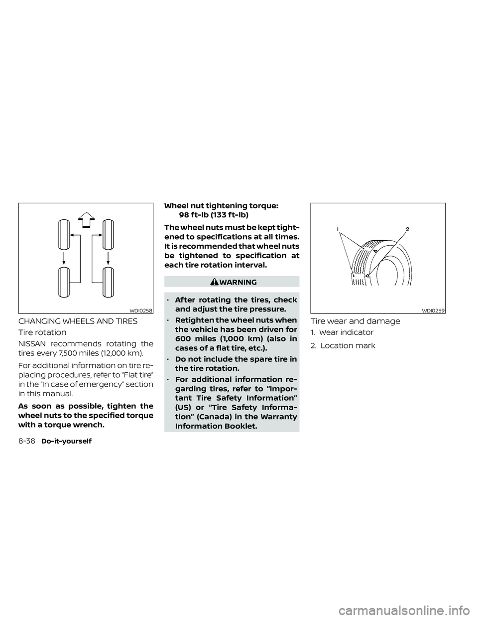
tires every 7,500 miles (12,000 km).
For additional information on tire re-
placing procedures, refer to “Flat tire”
in the “In case of emergency” section
in this manual.
As soon as possible, tighten the
wheel nuts to the specified torque
with a torque wrench.Wheel nut tightening torque:
98 f t-lb (133 f t-lb)
The wheel nuts must be kept tight-
ened to specifications at all times.
It is recommended that wheel nuts
be tightened to specification at
each tire rotation interval.
WARNING
• Af ter rotating the tires, check
and adjust the tire pressure.
• Retighten the wheel nuts when
the vehicle has been driven for
600 miles (1,000 km) (also in
cases of a flat tire, etc.).
• Do not include the spare tire in
the tire rotation.
• For additional information re-
garding tires, refer to “Impor-
tant Tire Safety Information”
(US) or “Tire Safety Informa-
tion” (Canada) in the Warranty
Information Booklet.
Tire wear and damage
1. Wear indicator
2. Location mark
WDI0258WDI0259
8-38Do-it-yourself