2021 NISSAN ARMADA steering
[x] Cancel search: steeringPage 125 of 603

ing. For more information, see “Extended
storage fuse switch” (P.8-21).
36. Headlight System Error
This warning appears if the LED head-
lights are malfunctioning. It is recom-
mended you have the system checked
by a NISSAN dealer.
37. Intelligent Lane Intervention (I-
LI)/Intelligent Blind Spot Interven-
tion (I-BSI) ON indicator
This indicator appears when one or more
of the following systems is activated.
.Intelligent Lane Intervention (I-LI)
. Intelligent Blind Spot Intervention (I-
BSI)
For more details, see “Intelligent Lane
Intervention (I-LI)” (P.5-31) or “Intelligent
Blind Spot Intervention (I-BSI)” (P.5-46).
38. Not Available: Poor Road Con-
ditions (if so equipped)
This warning may appear when the
Intelligent Blind Spot Intervention (I-BSI),
the Intelligent Lane Intervention (I-LI) or
the Intelligent Cruise Control (ICC) system
is engaged.
Under the following conditions, the I-BSI,
I-LI or the ICC system is automatically
canceled: .
When the Vehicle Dynamic Control
(VDC) or ABS operates
. When a wheel slips
The above system cannot be used in
some situations. (VDC operates and a
wheel slips.)
39-40. Currently unavailable/Cur-
rently not available (if so equipped)
This message appears and the Intelligent
Blind Spot Intervention (I-BSI) system, the
Intelligent Lane Intervention (I-LI) system
and Intelligent Cruise Control (ICC) sys-
tem will be turned off automatically under
the following conditions:
. When the VDC system is turned off.
. When the SNOW mode is selected.
. When the 4WD shift switch is in the 4H
or 4L position. (4WD models).
“Vehicle Dynamic Control (VDC) system”
(P.5-144), “SNOW mode” (P.5-135), “NISSAN
all-mode 4WD®” (P.5-124), “Intelligent Blind
Spot Intervention (I-BSI)” (P.5-46), “Intelli-
gent Lane Intervention (I-LI)” (P.5-31) and
“Intelligent Cruise Control (ICC)” (P.5-74).
41. Automatic Transmission (AT)
position indicator
This indicator shows the transmission
shift position.
See “Automatic transmission” (P.5-18) for
further details.
42. Rear Door Alert is activated
When the system is enabled, this message
appears when the Rear Door Alert system
is active and can remind the driver to
check the rear seat.
. Using the steering switch, the driver
can select “Dismiss Message” to clear
the display for a period of time.
. Using the steering switch, the driver
can select “Disable Alert” to disable the
horn alert for the remainder of the
current trip.
For additional information, see “Rear door
alert” (P.2-58).
WARNING
Selecting “Dismiss Message” during a
stop within a trip temporarily dis-
misses the message for that stop
without turning the system off.
Alerts can be provided for other
stops during the trip. Selecting “Dis-
Instruments and controls2-33
Page 128 of 603

2-36Instruments and controls
WAC0616X
TRIP COMPUTER
The trip computer switch is located on
the left side of the steering wheel. To
operate the trip computer, push the
switch.
Each time the left or right side of the
button is pushed, the display will
change.
1. Home
The Home mode shows the following
information.
. Vehicle speed
. Navigation (if so equipped) .
Audio
2. Audio
The audio mode shows the status of
audio information.
For more details, see NissanConnect®
Owner’s Manual.
3. Compass
This display indicates the heading direc-
tion of the vehicle.
4. Navigation
When the route guidance is set in the
navigation system, this item shows the
navigation route information.
For more details, see NissanConnect®
Owner’s Manual.
5. Vehicle speed (MPH or km/h)
The vehicle speed mode shows the cur-
rent vehicle speed and the average vehi-
cle speed since the last reset.
Resetting is done by pushing the left or
right side of the
button for longer
than 1 second.
Average vehicle speed:
The average vehicle speed display is
updated every 30 seconds. The first 30
seconds after a reset, the display shows
“———”.
6. Elapsed time and trip odometer
(mile or km)
Elapsed time:
The elapsed time mode shows the time
since the last reset. The displayed time
can be reset by pushing the left or right
side of the
button for longer than
1 second. (The trip odometer is also reset
at the same time.)
Trip odometer:
The trip odometer mode shows the total
distance the vehicle has been driven since
the last reset. Resetting is done by push-
ing the left or right side of the
button for longer than 1 second. (The
elapsed time is also reset at the same
time.)
7. Current fuel consumption and
average fuel consumption (MPG, l
(liter)/100 km or km/l)
Current fuel consumption:
The current fuel consumption mode
shows the current fuel consumption.
Average fuel consumption:
The average fuel consumption mode
shows the average fuel consumption
since the last reset. Resetting is done by
pushing the left or right side of the
Page 144 of 603
2-52Instruments and controls
SIC3672
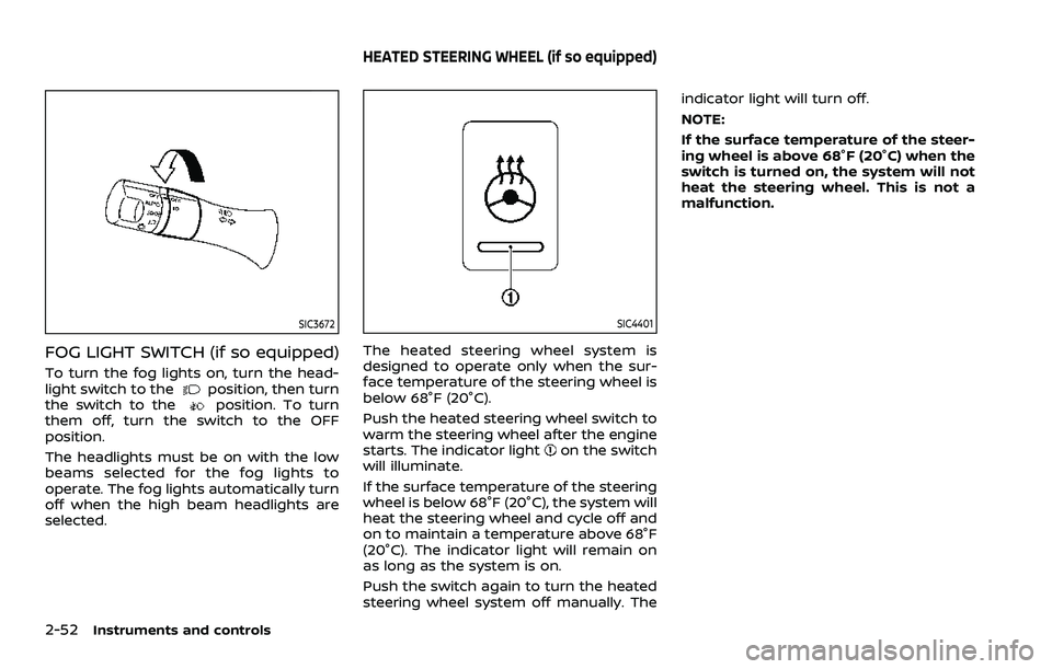
FOG LIGHT SWITCH (if so equipped)
To turn the fog lights on, turn the head-
light switch to theposition, then turn
the switch to theposition. To turn
them off, turn the switch to the OFF
position.
The headlights must be on with the low
beams selected for the fog lights to
operate. The fog lights automatically turn
off when the high beam headlights are
selected.
SIC4401
The heated steering wheel system is
designed to operate only when the sur-
face temperature of the steering wheel is
below 68°F (20°C).
Push the heated steering wheel switch to
warm the steering wheel after the engine
starts. The indicator light
on the switch
will illuminate.
If the surface temperature of the steering
wheel is below 68°F (20°C), the system will
heat the steering wheel and cycle off and
on to maintain a temperature above 68°F
(20°C). The indicator light will remain on
as long as the system is on.
Push the switch again to turn the heated
steering wheel system off manually. The indicator light will turn off.
NOTE:
If the surface temperature of the steer-
ing wheel is above 68°F (20°C) when the
switch is turned on, the system will not
heat the steering wheel. This is not a
malfunction.
HEATED STEERING WHEEL (if so equipped)
Page 145 of 603

SIC4444
To sound the horn, push the center pad
area of the steering wheel.
WARNING
Do not disassemble the horn. Doing
so could affect proper operation of
the supplemental front air bag sys-
tem. Tampering with the supple-
mental front air bag system may
result in serious personal injury.
WARNING
Do not use or allow occupants to use
the seat heater if you or the occu-
pants cannot monitor elevated seat
temperatures or have an inability to
feel pain in body parts that contact
the seat. Use of the seat heater by
such people could result in serious
injury.
CAUTION
.The battery could run down if the
seat heater is operated while the
engine is not running.
. Do not use the seat heater for
extended periods or when no one
is using the seat.
. Do not put anything on the seat
which insulates heat, such as a
blanket, cushion, seat cover, etc.
Otherwise, the seat may become
overheated.
. Do not place anything hard or
heavy on the seat or pierce it with
a pin or similar object. This may
result in damage to the heater. .
Any liquid spilled on the heated
seat should be removed immedi-
ately with a dry cloth.
. When cleaning the seat, never use
gasoline, thinner, or any similar
materials.
. If any malfunctions are found or
the heated seat does not operate,
turn the switch off and have the
system checked. It is recom-
mended you visit a NISSAN dealer
for this service.
Instruments and controls2-53
HORN HEATED SEATS
Page 148 of 603

2-56Instruments and controls
.Do not use the climate controlled
seat for extended periods or
when no one is using the seat.
. Do not put anything on the seat
which insulates heat, such as a
blanket, cushion, seat cover, etc.
Otherwise, the seat may become
overheated.
. Do not place anything hard or
heavy on the seat or pierce it with
a pin or similar object. This may
result in damage to the climate
controlled seat.
. Any liquid spilled on the seat
should be removed immediately
with a dry cloth.
. The climate controlled seat has
an air filter. Do not operate cli-
mate controlled seat without an
air filter. This may result in da-
mage to the system.
. When cleaning the seat, never use
gasoline, thinner, or any similar
materials.
. If any malfunctions are found or
the climate controlled seat does
not operate, turn the switch off
and have the system checked. It
is recommended you visit a
NISSAN dealer for this service.
SSD0956
The warning systems switch is used to
turn on and off the warning systems
(Lane Departure Warning (LDW) and Blind
Spot Warning (BSW) systems) that are
activated using the “Driver Assistance”
menu displayed in the vehicle information
display. (See “Driver Assistance” (P.2-21).)
When the warning systems switch is
turned off, the indicator
on the switch
is off. The indicator will also be off if all of
the warning systems are deactivated
using the settings menu.
The LDW system will vibrate the steering
wheel and blink the Lane Departure
Warning (LDW) indicator light (orange) to
alert the driver if the vehicle is traveling close to either the left or the right of a
traveling lane with detectable lane mar-
kers. (See “Lane Departure Warning (LDW)”
(P.5-26).)
The BSW system will turn on the side
indicator lights, on the outside mirrors, if
the radar sensors detect a vehicle in the
detection zone. If the turn signal is
activated in the direction of the detected
vehicle, a chime sounds twice and the
side indicator light will flash. (See “Blind
Spot Warning (BSW)” (P.5-38).)
WARNING SYSTEMS SWITCH (if so
equipped)
Page 183 of 603

3 Pre-driving checks and adjustments
Keys ........................................................................\
................................. 3-2Intelligent Key ........................................................................\
... 3-2
Valet hand-off ........................................................................\
... 3-4
Doors ........................................................................\
.............................. 3-4 Locking with mechanical key ...................................... 3-4
Opening and closing windows with the
mechanical key ........................................................................\
3-5
Locking with inside lock knob ..................................... 3-5
Locking with power door lock switch ................... 3-5
Automatic door locks ......................................................... 3-6
Child safety rear door lock ........................................... 3-6
Intelligent Key system .............................................................. 3-7 Intelligent Key operating range ................................. 3-9
Door locks/unlocks precaution .................................. 3-9
Intelligent Key operation .............................................. 3-10
Battery saver system ....................................................... 3-12
Warning signals .................................................................... 3-12
Troubleshooting guide ................................................... 3-13
Remote keyless entry system ......................................... 3-15 How to use remote keyless entry system ...... 3-16
Remote engine start (if so equipped) ....................... 3-19 Remote engine start operating range ............... 3-19
Remote starting the engine ....................................... 3-19
Extending engine run time ......................................... 3-20 Canceling a remote engine start ........................ 3-20
Conditions the remote engine start will
not work ........................................................................\
.......... 3-20
Hood ........................................................................\
............................ 3-21
Liftgate ........................................................................\
...................... 3-22 Operating manual liftgate ......................................... 3-22
Operating power liftgate (if so equipped) ...... 3-22
Auto closure ........................................................................\
3-25
Liftgate release lever ..................................................... 3-26
Fuel-filler door ........................................................................\
..... 3-26
Opening the fuel-filler door ...................................... 3-26
Fuel-filler cap ....................................................................... 3-26
Tilt/telescopic steering ........................................................ 3-29
Electric operation ............................................................. 3-29
Sun visors ........................................................................\
................ 3-29
Mirrors ........................................................................\
........................ 3-30
Inside mirror ........................................................................\
. 3-30
Outside mirrors .................................................................. 3-38
Vanity mirror ........................................................................\
3-40
Memory seat (if so equipped) ......................................... 3-40
Entry/exit function .......................................................... 3-40
Memory storage ................................................................ 3-41
Setting memory function ........................................... 3-42
System operation ............................................................. 3-42
Page 210 of 603

3-28Pre-driving checks and adjustments
SPA2753
To remove the fuel-filler cap:
1. Turn the fuel-filler cap counterclock-wise to remove.
2. Put the fuel-filler cap on the cap holder
while refueling.
To install the fuel-filler cap:
1. Insert the fuel-filler cap straight into the fuel-filler tube.
2. Turn the fuel-filler cap clockwise until a single click is heard.
WAD0274X
Loose Fuel Cap warning
The Loose Fuel Cap warning appears on
the vehicle information display when the
fuel-filler cap is not tightened correctly
after the vehicle has been refueled. It may
take a few driving trips for the warning to
be displayed.
To turn off the warning, perform the
following:
1. Remove and install the fuel-filler capas soon as possible. (See “Fuel-filler
cap” (P.3-26).)
2. Tighten the fuel-filler cap until it clicks.
3. Push the
switchon the
steering wheel to turn off the Loose Fuel Cap warning after tightening the
fuel-filler cap.
Page 211 of 603

WARNING
.Do not adjust the steering wheel
while driving. You could lose con-
trol of your vehicle and cause an
accident.
. Do not adjust the steering wheel
any closer to you than is neces-
sary for proper steering opera-
tion and comfort. The driver’s air
bag inflates with great force. If
you are unrestrained, leaning for-
ward, sitting sideways or out of
position in any way, you are at
greater risk of injury or death in a
crash. You may also receive ser-
ious or fatal injuries from the air
bag if you are up against it when
it inflates. Always sit back against
the seatback and as far away as
practical from the steering wheel.
Always use the seat belts.
SPA2754
ELECTRIC OPERATION
Tilt or telescopic operation
Move the leverto adjust the steering
wheel up or down, forward or rearward to
the desired position.
Entry/Exit function operation (if so
equipped):
The memory seat system will make the
steering wheel move up automatically
when the driver’s door is opened with
the ignition switch in the LOCK position.
This lets the driver get into and out of the
seat more easily.
For more information, see “Memory seat”
(P.3-40).
SIC3451
Pre-driving checks and adjustments3-29
TILT/TELESCOPIC STEERING SUN VISORS