2021 MERCEDES-BENZ GLE COUPE display
[x] Cancel search: displayPage 48 of 525
If a
vehicle occupant unfas tens a seat belt in the
re ar while theve hicle is motion, there ar seat
belt status display appears again.
In addition, a warning tone may sound. In this
case, there ar seat belt status display cannot be
hidden using the back button on the left-hand
side of thesteering wheel. Airbags
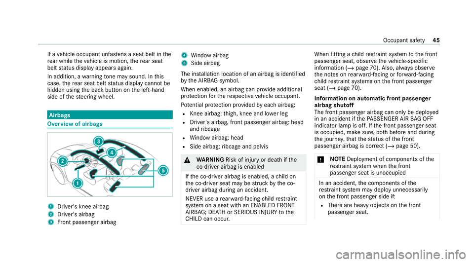
Overview of airbags
1
Driver's knee airbag
2 Driver's airbag
3 Front passenger airbag 4
Window airbag
5 Side airbag
The ins tallation location of an airbag is identified
by the AIRB AGsymbol.
When enabled, an airbag can pr ovide additional
pr otection forth ere spective vehicle occupant.
Pot ential pr otection pr ovided byeach airbag:
R Knee airbag: thigh, knee and lo wer leg
R Driver's airbag, front passenger airbag: head
and ribcage
R Window airbag: head
R Side airbag: ribcage and pelvis &
WARNING Risk of injury or death ifthe
co-driver airbag is enabled
If th e co-driver airbag is enabled, a child on
th e co-driver seat may be stru ck bythe co-
driver airbag during an accident.
NEVER use a rear wa rd-facing child restra int
sy stem on a seat with an ENABLED FRONT
AIRB AG; DEAT H or SERIOUS INJU RYtothe
CH ILD can occur. When
fitting a child restra int sy stem tothe front
passenger seat, obser vetheve hicle-specific
information (/ page 70). Also, alw ays obser ve
th e no tes on rear wa rd-facing or forw ard-facing
ch ild restra int sy stems on the front passenger
seat (/ page 70).
Information on automatic front passenger
airbag shutoff
The front passenger airbag can only be deplo yed
in an accident if thePA SSENGER AIR BAG OFF
indicator lamp is off. If the front passenger seat
is occupied, make sure, bo thbefore and during
th e journe y,that thest atus of the front
passenger airbag is cor rect (/ page 50).
* NO
TEDeployment of components of the
re stra int sy stem when the front
passenger seat is unoccupied In an accident,
the components of the
re stra int sy stem may deploy unnecessarily
on the front passenger side if:
R There are heavy objects on the front
passenger seat. Occupant saf
ety45
Page 53 of 525
Fu
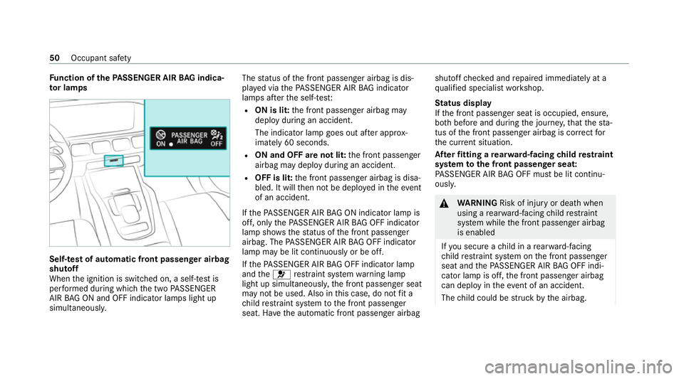
nction of thePA SSENGER AIR BAG indica‐
to r lamps Self-
test of automatic front passenger airbag
shu toff
When the ignition is switched on, a self-test is
per form ed during which the two PASSENGER
AIR BAG ON and OFF indicator lamps light up
simul taneously. The
status of the front passenger airbag is dis‐
pla yed via thePA SSENGER AIR BAG indicator
lamps af terth e self-tes t:
R ON is lit: the front passenger airbag may
deploy during an accident.
The indicator lamp goes out af ter appro x‐
ima tely 60 seconds.
R ON and OF F are not lit: the front passenger
airbag may deploy during an accident.
R OFF is lit: the front passenger airbag is disa‐
bled. It will then not be deplo yed in theev ent
of an accident.
If th ePA SSENGER AIR BAG ON indicator lamp is
off, on lythePA SSENGER AIR BAG OFF indicator
lamp sho ws thest atus of the front passenger
airbag. The PASSENGER AIR BAG OFF indicator
lamp may be lit continuously or be off.
If th ePA SSENGER AIR BAG OFF indicator lamp
and the0075 restra int sy stem warning lamp
light up simultaneousl y,the front passenger seat
may not be used. Also in this case, do not fit a
ch ild restra int sy stem tothe front passenger
seat. Ha vethe automatic front passenger airbag shutoff
checked and repaired immediately at a
qu alified specialist workshop.
St atus display
If th e front passenger seat is occupied, ensure,
bo th before and during the journe y,that thest a‐
tus of the front passenger airbag is cor rect for
th e cur rent situation.
Af terfitting a rear wa rd-facing child restra int
sy stem tothe front passenger seat:
PA SSENGER AIR BAG OFF must be lit continu‐
ousl y. &
WARNING Risk of injury or death when
using a rear wa rd-facing child restra int
sy stem while the front passenger airbag
is enabled
If yo u secure a child in a rear wa rd-facing
ch ild restra int sy stem on the front passenger
seat and thePA SSENGER AIR BAG OFF indi‐
cator lamp is off, the front passenger airbag
can deploy in theeve nt of an accident.
The child could be stru ck bythe airbag. 50
Occupant saf ety
Page 57 of 525
th
e dis tance between the door and theve hicle
occupant.
If PRE-SAFE ®
Impulse Side has been deplo yed or
is faulty, thePRE-SAFE impulse side inoperative
See Owner's Manual( /page 409) display mes‐
sage appears. Au
tomatic measures af ter an accident
Depending on the type and se verity of the acci‐
dent, and depending on theve hicle's equipment,
th efo llowing measures can be implemente d,for
ex ample:
R automatic braking (post-collision brake)
R activating the hazard warning lights
R triggering an automatic emerge ncy call
(/ page 319)
R swit ching off the engine
To restart theve hicle, switch the ignition off
and switch it back on (/ page163).
Depending on the type and se verity of the
accident, it is possible that theve hicle can
no longer be star ted. R
switching off the fuel supply
R unlocking theve hicle doors
R lowe ring the side windo ws
R displaying the emer gency guide in the multi‐
media sy stem display
R switching on the interior lighting
Fu nction of the post-collision brake
Depending on the accident situation, the post-
collision brake can minimise the se verity of a fur‐
th er collision or even avo id it.
If an accident is de tected, the post-collision
brake can implement automatic braking. When
th eve hicle has come toast andstill, the electric
parking brake is automatically applied.
The driver can cancel automatic braking bytak‐
ing thefo llowing actions:
R braking more stronglythan automatic brak‐
ing
R fully depressing the accelera tor pedal with
fo rce Safely transporting
children in theve hicle Alw
ays obser vewhen children are tr avelling
in theve hicle %
Also strictly obser vethe saf ety no tesfo rthe
specific situation. In this wa yyo u can recog‐
nise po tential risks and avoid dangers if chil‐
dren are tr avelling in theve hicle
(/ page 55).
Be diligent
Bear in mind that negligence when securing a
ch ild in thech ild restra int sy stem may ha veseri‐
ous consequences. Alw ays be diligent in secur‐
ing a child carefully before everyjou rney.
To impr oveprotection forch ildren younger than
12 years old or under 1.50 m in height,
Mercedes-Benz recommends you obse rvethe
fo llowing information:
R Alw ays secure thech ild in a child restra int
sy stem suitable forth is Mercedes-Benz vehi‐
cle.
R The child restra int sy stem must be appropri‐
ate tothe age, weight and size of thech ild. 54
Occupant saf ety
Page 116 of 525
Memory function
Fu
nction of the memory function &
WARNING Risk of an accident if the
memory function is used while driving
If yo u use the memory function on the driv‐
er's side while driving, you could lose cont rol
of theve hicle as a result of the adjustments
being made. #
Only use the memory function on the
driver's side when theve hicle is station‐
ar y. &
WARNING Risk of entrapment when
adjusting the seat with the memory func‐
tion
When the memory function adjusts the seat,
yo u and other vehicle occupants – particu‐
lar lych ildren – could become trapped. #
During the adjustment process of the
memory function, make sure that no one has any body parts in
the sweep of
th e seat. #
If someone becomes trapped, press a
preset position button or seat adjust‐
ment switch immediately. &
WARNING Risk of entrapment if the
memory function is activated bychildren
Children could become trapped if they acti‐
va te the memory function, particularly when
unattended. #
Never lea vechildren unat tended in the
ve hicle. #
When leaving theve hicle, alw aysta ke
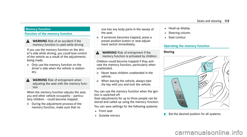
th eke y with you and lock theve hicle. Yo
u can use the memory function when the igni‐
tion is switched off.
Seat adjustments for up tothre e people can be
st ored and called up using the memory function.
Yo u can sa vesettings forth efo llowing sy stems:
R Front seat
R Outside mir rors R
Head-up display
R Steering column
R Seat conto ur Ope
rating the memo ryfunction Sto
ring #
Set the desired position for all sy stems. Seats and
stowing 11 3
Page 134 of 525
R
Depending on theve hicle equipment, the
mobile phone is connected totheve hicle's
ex terior aerial via thech arging module.
R The charging function and wireless connec‐
tion of the mobile phone totheve hicle's
ex terior aerial are only available if the ignition
is switched on.
R Small mobile phones may not be able tobe
ch arge d in everyposition of the mobile
phone stowage compartment.
R Largemobile phones which do not rest flat in
th e mobile phone stowage compartment may
not be able tobe charge d or connec ted with
th eve hicle's exterior aerial.
R The mobile phone may heat up during the
ch arging process. This may also depend on
th e applications (apps) cur rently open in the
bac kground.
R Toensure more ef ficient charging and con‐
nection with theve hicle's exterior aerial,
re mo vethe pr otective co ver from the mobile
phone. Pr otective co vers which are neces‐
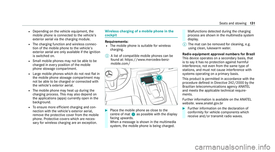
sary for wireless charging are an exception. Wire
lesscharging of a mobile phone in the
cockpit Re
quirements:
R The mobile phone is suitable for wireless
ch arging.
% A list of compatible mobile phones can be
found at: https://www.mercedes-benz-
mobile.com/ #
Place the mobile phone as close tothe
centre of mat 1as possible with th e display
fa cing up wards.
When a message is shown in the multimedia
sy stem, the mobile phone is being charge d. Malfunctions de
tected duri ngthech arging
process are shown in the multimedia sy stem
displa y.
% The mat can be remo vedfo r cleaning, e.g.
using clean, luk ewarmwate r.
Ra dio equipment appr oval numbers for Brazil
This device operates on a secondary basis, that
is to say it has no pr otection against harmful
inter fere nce, not even from the same type of
st ations, and must not cause inter fere nce wi th
sy stems operating on a primary basis.
This product is permitted in accordance with the
procedure defined in Directive 242/2000 bythe
Brazilian telecommunications agency AN ATEL
and meets the applicable tech nical requ ire‐
ments.
Fu rther information is available on the AN ATEL
we bsite. www.anatel.go v.br #
Further information on the declaration of
confo rmity forve hicle components which
re cei veand/or transmit radio wav es. Seats and
stowing 131
Page 136 of 525
Exterior lighting
Note
s on adjusting the lights when driving
abroad Ve
hicles with Intelligent Light Sy stem: The
headlamps are automatically adjus ted when the
ve hicle enters countries in which traf fic drives
on theot her side of thero ad.
In thefo llowing cases, check the headlamp set‐
ting and change it manually if necessary:
R Ifth eDipped-beam setting (left/right-side
traffic) Manual adjustment only display mes‐
sage is displa yed.
R Ifth eCheck dipped-beam setting (left/right-
side traffic) display message is displa yed.
Once the headlamps ha vebeen con verted:
R Oncoming tra ffic will not be dazzled.
R The edge of thero ad will not be illuminated
as far or as high.
R The "mo torw ay mode" and "enhanced fog
light" functions will not be available. Information about lighting sy
stems and your
re sponsibility The
various lighting sy stems of theve hicle are
only aids. The driver of theve hicle is responsible
fo r cor rect vehicle illumination in accordance
with the pr evailing light and visibility conditions,
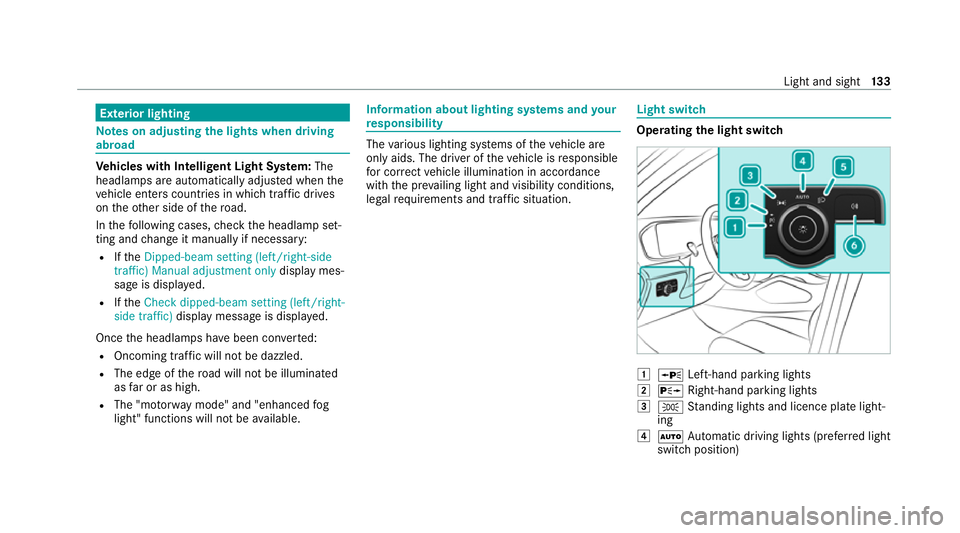
legal requirements and traf fic situation. Light switch
Ope
rating the light switch 0047
0063 Left-hand pa rking lights
0048 0064 Right-hand parking lights
0049 0060 Standing lights and licence plate light‐
ing
004A 0058 Automatic driving lights (prefer red light
switch position) Light and sight
13 3
Page 142 of 525
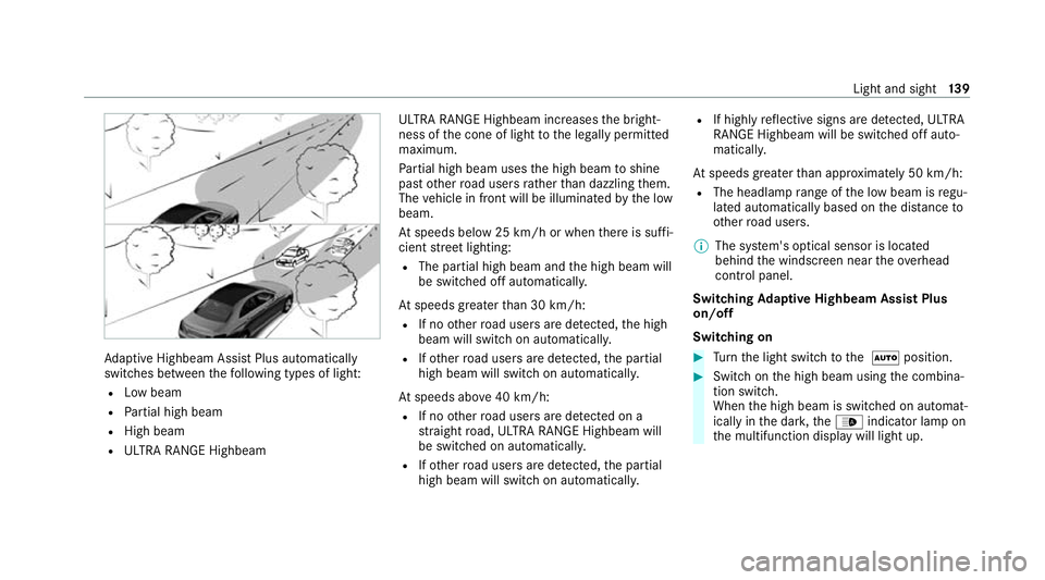
Ad
aptive Highbeam Assist Plus automatically
swit ches between thefo llowing types of light:
R Low beam
R Partial high beam
R High beam
R ULTRA RANGE Highbeam ULTRA RANGE Highbeam inc
reases the bright‐
ness of the cone of light tothe legally permitted
maximum.
Pa rtial high beam uses the high beam toshine
past other road users rath er than dazzling them.
The vehicle in front will be illuminated bythe low
beam.
At speeds below 25 km/h or when there is suf fi‐
cient stre et lighting:
R The partial high beam and the high beam will
be switched off automaticall y.
At speeds greater than 30 km/h:
R If no other road users are de tected, the high
beam will switch on automaticall y.
R Ifot her road users are de tected, the partial
high beam will switch on automaticall y.
At speeds abo ve40 km/h:
R If no other road users are de tected on a
st ra ight road, ULTRA RANGE Highbeam will
be swit ched on automaticall y.
R Ifot her road users are de tected, the partial
high beam will switch on automaticall y.R
If highly reflective signs are de tected, ULTRA
RANGE Highbeam will be switched off au to‐
matical ly.
At speeds greater than appr oximately 50 km/h:
R The headlamp range of the low beam is regu‐
lated automatically based on the dis tance to
ot her road users.
% The sy stem's optical sensor is located
behind the windscreen near theove rhead
control panel.
Switching Adaptive Highbeam Assist Plus
on/off
Switching on #
Turn the light switch tothe 0058 position. #
Switch on the high beam using the combina‐
tion switch.
When the high beam is switched on automat‐
ically in the dar k,the00CE indicator lamp on
th e multifunction display will light up. Light and sight
13 9
Page 147 of 525
#
Slide catch 2inthe direction of ar row 3
until it engages in the locking position. #
Make sure that the wiper blade is seated cor‐
re ctly. #
Foldthe wiper arms back onto the wind‐
screen. #
Switch on the ignition. #
Press the00D4 button on the combination
switch.
The wiper arms will return tothe original
position. #
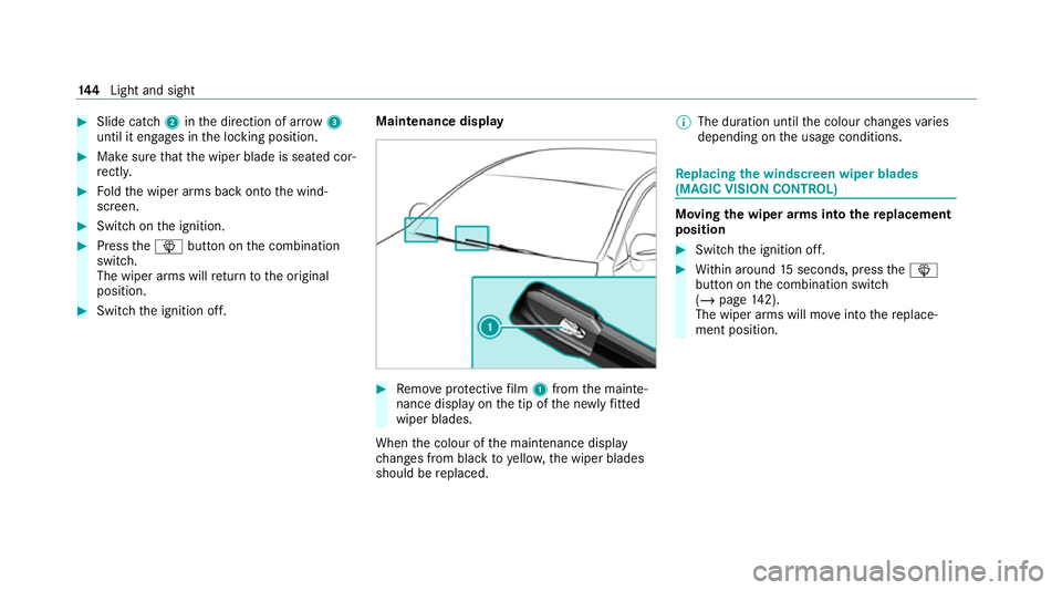
Switch the ignition off. Maintenance display #
Remo veprotective film 1 from the mainte‐
nance display on the tip of the newly fitted
wiper blades.
When the colour of the maintenance display
ch anges from black to yellow, the wiper blades
should be replaced. %
The duration until the colour changes varies
depending on the usage conditions. Re
placing the windsc reen wiper blades
(MAGIC VISION CONT ROL) Moving
the wiper arms into there placement
position #
Switch the ignition off. #
Within around 15seconds, press the00D4
button on the combination switch
(/ page 142).
The wiper arms will mo veinto there place‐
ment position. 14 4
Light and sight