2021 MERCEDES-BENZ GLC SUV USB port
[x] Cancel search: USB portPage 114 of 481
R
secure the load using the tie-down eyes and
distribute the load evenly. St
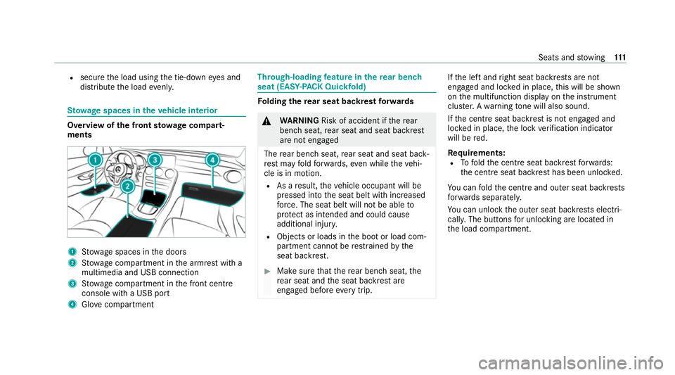
ow age spaces in theve hicle interior Overview of
the front stowage compa rt‐
ments 1
Stow age spaces in the doors
2 Stow age compartment in the armrest with a
multimedia and USB connection
3 Stow age compartment in the front cent re
console with a USB port
4 Glovecompa rtment Through-loading
feature in there ar ben ch
seat (EAS Y-PA CK Quickfold) Fo
lding there ar seat backrest forw ards &
WARNING Risk of accident if there ar
ben chseat, rear seat and seat backrest
are not engaged
The rear ben chseat, rear seat and seat back‐
re st may fold forw ards, even while theve hi‐
cle is in motion.
R As a result, theve hicle occupant will be
pressed into the seat belt with increased
fo rc e. The seat belt will not be able to
pr otect as intended and could cause
additional injur y.
R Objects or loads in the boot or load com‐
partment cann otbe restra ined bythe
seat backrest. #
Make sure that there ar ben chseat, the
re ar seat and the seat backrest are
engaged before everytrip. If
th e left and right seat backrests are not
engaged and loc ked in place, this will be shown
on the multifunction display on the instrument
clus ter.A wa rning tone will also sound.
If th e cent reseat backrest is not engaged and
loc ked in place, the lock verification indicator
will be red.
Re quirements:
R Tofold the cent reseat backrest forw ards:
th e cent reseat backrest has been unloc ked.
Yo u can fold the cent reand outer seat backrests
fo rw ards separatel y.
Yo u can unlo ckthe outer seat backrests electri‐
cally. The buttons for unlocking are located in
th e load compartment. Seats and
stowing 111
Page 126 of 481
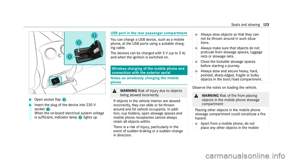
#
Open soc ketflap 3. #
Insert the plug of the device into 230 V
soc ket1.
When the on-board electrical sy stem voltage
is suf ficient, indicator la mp2lights up. USB port in
there ar passenger comp artment Yo
u can charge a USB device, such as a mobile
phone, at the USB ports using a suitable charg‐
ing cable.
The devices can be charge d with 5 V (up to3 A)
and when the ignition is switched on. Wire
lesscharging of the mobile phone and
connection with theex terior aerial Note
s on wirelessly charging the mobile
phone &
WARNING Risk of injury duetoobjects
being stowed incor rectly
If objects in theve hicle interior are stowed
incor rectly, they can slide or be thrown
around and hit vehicle occupants. In addi‐
tion, cup holders, open stowage spaces and
mobile phone recep tacles cannot al ways
re tain all objects within.
There is a risk of injur y,particularly in the
ev ent of sudden braking or a sudden change
in direction. #
Alw aysstow objects so that they can‐
not be throw n around in su chsitua‐
tions. #
Alw ays make sure that objects do not
pr otru de from stowage spaces, luggage
nets or stowage nets. #
Close the loc kable stow age spaces
before starting a journe y. #
Alw aysstow and secure heavy, hard,
poin ted, sharp-edged, fragile or bulky
objects in the boot/load compartment. Obser
vethe no tes on loading theve hicle. &
WARNING Risk offire from placing
objects in the mobile phone stowage
compartment
Placing other objects in the mobile phone
stow age compartment could con stitute a fire
hazard. #
Apart from a mobile phone, do not
place any other objects in the mobile Seats and
stowing 12 3
Page 287 of 481
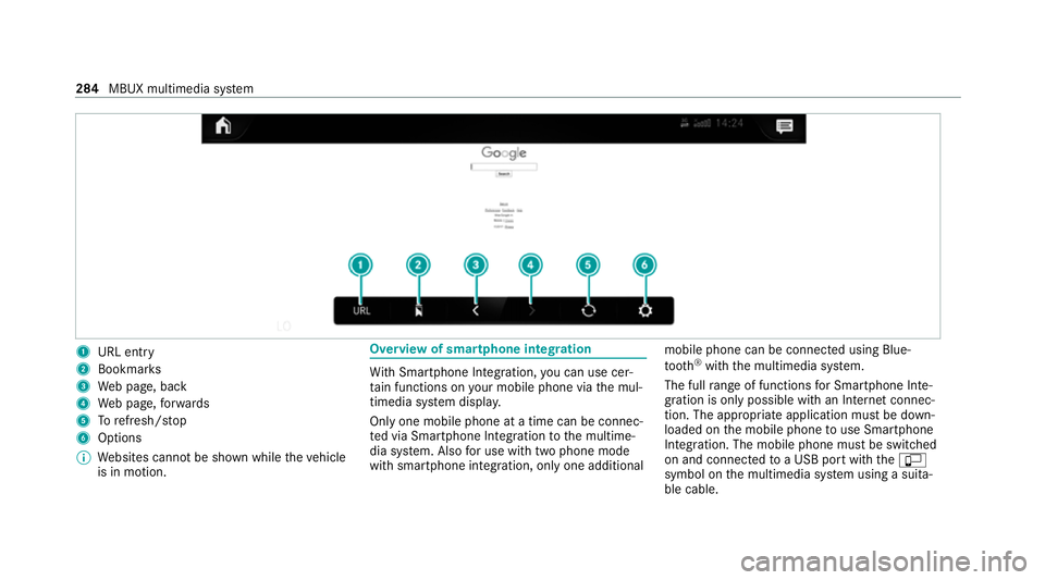
1
URL entry
2 Bookmar ks
3 Web page, back
4 Web page, forw ards
5 Torefresh/s top
6 Options
% Websites cann otbe shown while theve hicle
is in motion. Overview of smartphone integ
ration Wi
th Smartphone Integration, you can use cer‐
ta in functions on your mobile phone via the mul‐
timedia sy stem displa y.
Only one mobile phone at a time can be connec‐
te d via Smartphone Integ ration tothe multime‐
dia sy stem. Also for use with two phone mode
with smartphone integration, only one additional mobile phone can be connected using Blue‐
tooth
®
with the multimedia sy stem.
The full range of functions for Smartphone Inte‐
gration is only possible with an Internet connec‐
tion. The appro priate application must be down‐
loaded on the mobile phone touse Smartphone
In te gration. The mobile phone must be switched
on and connected toa USB port with theç
symbol on the multimedia sy stem using a suita‐
ble cable. 284
MBUX multimedia sy stem
Page 448 of 481
Wheels/rims......................................... 309
Wi
ndo ws................................................ 309
Wi per blades.........................................3 09
Carpet (Care).............................................. 310
Changing gears
Manually. ............................................... 16 8
Changing hub caps .................................. .345
Charging Battery (vehicle).................................... 325
USB port................................................ 12 3
Chassis Damping characteristics....................... .217
DY NA MIC BODY CONTROL.................... 217
Chassis le vel (AIR BODY CONT ROL)
Setting.................................................. .219
Child saf ety lock
Re ar door................................................ 70
Re ar side wind ows................................... 72
Child seat App rova l categories................................ .58
At tach ing (no tes).....................................58
Basic instructions.................................... 53
Fr ont passenger seat (no tes)...................68 Fr
ont passenger seat (without auto‐
matic airbag shutoff)...............................68
ISOFIX/i-Size (fitting).............................. 62
No tes on risks and dangers..................... 54
Re commended child restra int sy stems.... 57
Seats suitable for belt-secu redch ild
re stra int sy stems..................................... 65
Seats suitable for i‑Size child
re stra int sy stems..................................... 61
Seats suitable for ISOFIX child
re stra int sy stems..................................... 60
Securing on the co-driver seat................69
Secu ring on there ar seat........................ 66
To pTe ther............................................... 64
Child ren
Av oiding dangers in theve hicle............... 54
Basic instructions.................................... 53
Cho ck
St orage location.................................... 344
Chock see Chock
Cleaning see Care Climate control
Activating/deactivating the A/C
function (contro l panel)........................ .143
Ac tivating/deactivating the A/C
function (MBUX multimedia sy stem)..... 14 3
Ac tivating/deactivating the synchro‐
nisation function (contro l panel)............14 4
Ac tivating/deactivating the synchro‐
nisation function (MBUX multimedia
sy stem).................................................. 14 4
Air-reci rculation mode...........................1 45
Au tomatic control.................................. 14 4
Calling up the air conditioning menu..... 14 3
Climate style function............................1 44
Demi sting the windscreen..................... 14 2
Demi sting windo ws............................... 14 5
Fr ont air vents........................................ 151
Inserting/removing theflacon (fra‐
gr ance sy stem)...................................... 14 6
Ionisation............................................... 14 5
No te...................................................... 14 2
Re ar air vents......................................... 151
Re sidual heat......................................... 14 5
Setting (MBUX multimedia sy stem)....... 14 3
Setting the air distribution..................... 14 2
Setting the air flow ................................. 14 2 Index
445
Page 473 of 481
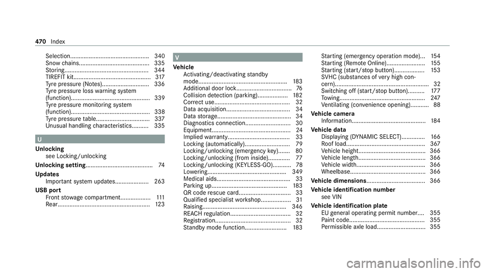
Selection............................................... 340
Snow
chains.......................................... 335
St oring..................................................3 44
TIREFIT kit..............................................3 17
Ty re pressure (N otes)............................ 336
Ty re pressure loss warning sy stem
(function)............................................... 339
Ty re pressure monitoring sy stem
(function)............................................... 338
Ty re pressure table................................ 337
Un usual handling characteristic s.......... 335 U
Un locking
see Locking/unlocking
Un locking setting ........................................ 74
Up dates
Impor tant sy stem updates....................2 63
USB port Front stow age compartment.................. 111
Re ar...................................................... .123 V
Ve hicle
Ac tivating/deactivating standby
mode.................................................... .183
Ad ditional door loc k................................ .76
Collision de tection (pa rking).................. 182
Cor rect use............................................. 32
Data acquisition...................................... 34
Data storage............................................ 34
Diagnostics connection........................... 30
Equipment...............................................24
Implied warrant y..................................... 33
Locking (automatically). .......................... 79
Locking/unlocking (emergency key)....... 80
Locking/unlocking (from inside)............. 77
Locking/unlocking (KEYLESS-GO)...........78
Lo we ring............................................... 349
Medical aids............................................ 33
Pa rking up............................................ .183
QR code rescue card............................... 33
Qualifi ed specialist workshop.................. 31
Ra ising.................................................. 346
REA CHregulation.................................... 32
Re gistration............................................. 32
St andby mode function........................ .183 St
arting (eme rgency operation mode)...1 54
St arting (Remo teOnline).......................1 55
St arting (s tart/s top button).................. 15 3
SV HC (subs tances of very high con‐
cern)........................................................ 32
Switching off (s tart/s top button).......... 17 7
To wing.................................................. .247
Ve ntilating (co nvenience opening)........... 88
Ve hicle camera
Information............................................ 184
Ve hicle data
Displ aying (DYNAMIC SELECT).............. 16 6
Ro of load............................................... 367
Ve hicle height........................................3 66
Ve hicle length........................................3 66
Ve hicle width.........................................3 66
Wheelbase............................................. 366
Ve hicle dimensions ................................... 366
Ve hicle identification number
see VIN
Ve hicle identification plate
EU general operating pe rmit number....3 55
Pa int code............................................. 355
Pe rm issible axle load............................ .355 47 0
Index