2021 MERCEDES-BENZ GLC SUV battery
[x] Cancel search: batteryPage 224 of 481
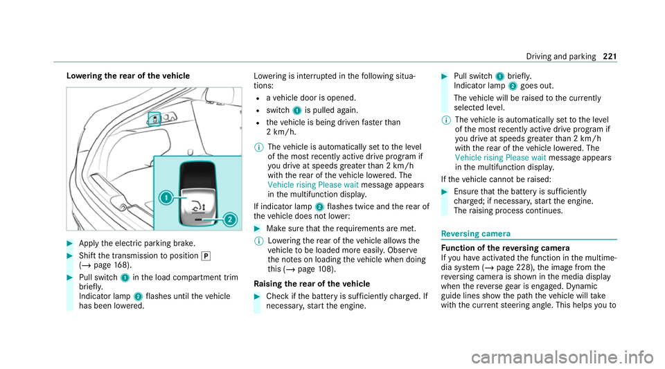
Lo
weri ngthere ar of theve hicle #
Apply the electric parking brake. #
Shift the transmission toposition j
(/ page 168). #
Pull switch 1inthe load compartment trim
brief ly.
Indicator lamp 2flashes until theve hicle
has been lo wered. Lo
we ring is inter rupte d in thefo llowing situa‐
tions:
R ave hicle door is opened.
R switch 1is pulled again.
R theve hicle is being driven fasterthan
2 km/h.
% The vehicle is automatically set tothe le vel
of the most recently acti vedrive program if
yo u drive at speeds greater than 2 km/h
with there ar of theve hicle lo wered. The
Vehicle rising Please wait message appears
in the multifunction displa y.
If indicator lamp 2flashes twice and there ar of
th eve hicle does not lo wer: #
Make sure that there qu irements are met.
% Lowe ring there ar of theve hicle allo wsthe
ve hicle tobe loaded more easil y.Obser ve
th e no tes on loading theve hicle when doing
th is (/ page108).
Ra ising there ar of theve hicle #
Che ckifth e battery is suf ficiently charge d. If
necessar y,start the engine. #
Pull switch 1briefly.
Indicator lamp 2goes out.
The vehicle will be raised tothe cur rently
selected le vel.
% The vehicle is automatically set tothe le vel
of the most recently acti vedrive program if
yo u drive at speeds greater than 2 km/h
with there ar of theve hicle lo wered. The
Vehicle rising Please wait message appears
in the multifunction displa y.
If th eve hicle cannot be raised: #
Ensure that the battery is suf ficiently
ch arge d; if necessar y,start the engine.
The raising process continues. Re
versing camera Fu
nction of there ve rsing camera
If yo u ha veactivated the function in the multime‐
dia sy stem (/ page 228), the image from the
re ve rsing camera is shown in the media display
when there ve rsege ar is engaged. Dynamic
guide lines show the path theve hicle will take
with the cur rent steering angle. This helps youto Driving and pa
rking 221
Page 246 of 481
If
th e ball neck is not securely loc ked in place,
th eCheck trailer hitch lock message will appear
on the multifunction displa y.Coupling up/uncoupling a trailer
&
WARNING Risk of injury fromtheve hicle
le ve l being changed
Ve hicles with le vel control sy stem: the
ve hicle le vel may be changed unin tentional ly,
e.g. by ot her persons. You may become trap‐
ped if you couple up or uncouple a trailer
while theve hicle le vel is changing. In addi‐
tion, other people could become trapped if
th eir limbs are between theve hicle body and
th e tyres or underneath theve hicle.
When coupling up or uncoupling a trailer,
make sure that: #
The doors or tailgate are not opened or
closed. #
You do not initiate the le vel control sys‐
te m and do not operate theDY NA MIC
SELECT switch. #
Do not lock or unlock theve hicle. Re
quirements:
R The ball neck is extended and engaged in a
secu rely loc ked position.
Tr ailers with a 7-pin plug can be connec tedto
th eve hicle with thefo llowing adap ters:
R Adapter plug
R Adapter cable
The trailer will be cor rectly de tected bytheve hi‐
cle only if thefo llowing conditions are me t:
R The trailer is connected cor rectl y.
R The trailer lighting sy stem is in working
order.
The functions of thefo llowing sy stems will be
af fected bya cor rectly connected trailer:
R ESP ®
trailer stabilisation
R Trailer Manoeuvering Assist
R Active Lane Keeping Assist
R Parking Assist PARKTRONIC
R Active Parking Assist R
Blind Spot Assist or Active Blind Spot Assi st
R Drive AwayAssi st
R Cross Traf fic Alert
R Reversing camera
R 360° camera
R AIR BODY CONTROL
Coupling up a trailer
* NO
TEDama getothest ar ter battery due
to full dischar ge Charging
the trailer battery using the po wer
supply of the trailer can damage thest ar ter
batter y. #
Do not use theve hicle's po wer supply
to charge the trailer batter y. #
Remo vethe co ver cap from the ball head and
st ore it in a safe place. #
Position the trailer on a le vel sur face behind
th eve hicle and couple it up totheve hicle. Driving and parking
243
Page 258 of 481
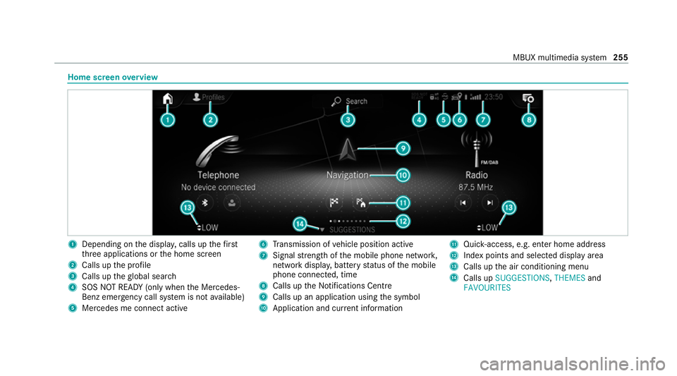
Home screen
overview 1
Depending on the displa y,calls up thefirst
th re e applications or the home screen
2 Calls up the profile
3 Calls up theglobal sear ch
4 SOS NOT READY (only when the Mercedes-
Benz emer gency call sy stem is not available)
5 Mercedes me connect active 6
Transmission of vehicle position active
7 Signal stre ngth of the mobile phone networ k,
network displ ay, battery status of the mobile
phone connected, time
8 Calls up the Notifications Centre
9 Calls up an application using the symbol
A Application and cur rent information B
Quick-access, e.g. enter home address
C Index points and selected displ ayarea
D Calls up the air conditioning menu
E Calls up SUGGESTIONS, THEMESand
FAVOURITES MBUX multimedia sy
stem 255
Page 278 of 481
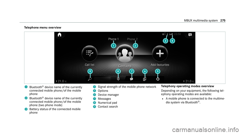
Te
lephone menu overview 1
Blue tooth ®
device name of the cur rently
connected mobile phone/of the mobile
phone
2 Blue tooth ®
device name of the cur rently
connected mobile phone/of the mobile
phone (two phone mode)
3 Battery status of the connected mobile
phone 4
Signal stre ngth of the mobile phone network
5 Options
6 Device manager
7 Messages
8 Nume rical pad
9 Contact search Te
lephony operating modes overview
Depending on your equipment, thefo llowing tel‐
ephony operating modes are available:
R A mobile phone is connec tedto the multime‐
dia sy stem via Blue tooth®
. MBUX multimedia sy
stem 275
Page 289 of 481
Overview of
the Mercedes-Benz emer gency
call sy stem The Mercedes-Benz emer
gency call sy stem can
help todecisively reduce the time between an
accident and the ar riva l of emer gency services
at the site of the accident. It helps locate an
accident site in places that are dif ficult to
access.
The emer gency call can be made au tomatical ly
( / page 286) or manually (/ page 287). Only
make emer gency calls if you or others are in
need of rescue. Do not make an emergency call
in theeve nt of a breakdown or a similar situa‐
tion.
Yo u can find more information on there gional
av ailability of eCall at: https://www.mercedes-
benz-mobile.com/ext ra/ecall/
Messages on the displ ay
The following messages appear in the display:
R SOS NOT READY: the ignition is not on or
eCall is not available . This does not necessa‐
ri ly indica tecompl etefa ilure of the emer‐ ge
ncy call sy stem. Emer gency calls call still
be transmitte d.
The display only refers to theve hicle and
does not take account of theav ailability of
mobile phone networ ksand the Mercedes-
Benz emer gency call centre.
The functional readiness of the emer gency
call sy stem on theve hicle can be seen when
th eSOS NOT READY display disappears once
th e ignition is switched on.
R G: The icon appears in the display during
an active emer gency call.
% Ifth ere is a malfunction in the Mercedes-
Benz emer gency call sy stem (e.g. a fault with
th e speaker, microphone, airbag, SOS but‐
to n), a cor responding message appears in
th e multifunction display of the instrument
clus ter. Tr
iggering an automatic Mercedes‑Benz
emer gency call Re
quirements:
R The ignition is switched on. R
The star ter battery is suf ficiently charge d.
The Mercedes‑Benz emer gency call sy stem trig‐
ge rs an emer gency call au tomatical lyin thefo l‐
lowing cases:
R After activation of there stra int sy stems such
as airbags or seat belt tensioners af ter an
accident
The emergency call has been made:
R Avo ice connection is made tothe
Mercedes‑Benz emer gency call centre.
R A messa gewith accident data is transmitted
to the Mercedes‑Benz emer gency call centre.
The Mercedes‑Benz emergency call centre
can transmit theve hicle position data toone
of the public emer gency services call cen‐
tres.
R Under cer tain circums tances da tais also
transmitte d inthevo ice channel tothe
Mercedes‑Benz emer gency call centre.
This allo wsmeasu resfo rre scue, reco very or
to wing toa Mercedes‑Benz Service Cent reto
be initiated quickl y. 286
MBUX multimedia sy stem
Page 291 of 481
Ending an unin
tentionally triggered manual
Mercedes-Benz emer gency call #
On the multifunction steering wheel:
select ~. Data transfer of
the Mercedes-Benz emer‐
ge ncy call sy stem In
theeve nt of an auto matic or manual emer‐
ge ncy call thefo llowing data is transmitte d,for
ex ample:
R Vehicle's GPS position data
R GPS position data on thero ute
(a few hund red metres before the incident)
R Direction of tra vel
R Vehicle identification number
R Vehicle drive type
R Number of people de term ined tobe in the
ve hicle
R Whe ther Mercedes me connect is available
or not
R Whe ther the emer gency call was initiated
manually or automatically R
Time of the accident
R Language setting on the multimedia sy stem
Fo r accident clarification purposes, thefo llowing
measures can be take n up toan hour af terthe
emer gency call has been initia ted:
R The cur rent vehicle position can be de ter‐
mined.
R Avo ice connection totheve hicle occupants
can be es tablished.
% ForRu ssia: various functions, e.g. receiving
traf fic information, cannot be per form ed for
up totwo hou rsafte r sending an emer gency
call. Self diagnosis function of the eme
rgency call
sy stem Yo
ur car verifies the operability of the emer‐
ge ncy call sy stem each time the ignition is ON.
In case of sy stem failure, you will be informed
with text messa geon the instrument clus ter and
with red indicator SOS NOT READY onthe dis‐
pla y. Please, make sure,
that during 30 seconds af ter
switching ignition ON there d indicator SOS
NOT READY inthe upper right corner of display
is switched OFF, this means the emer gency call
sy stem passed diagnostics successfully. St
arting/ending ERA-GLONASS test mode Re
quirements:
R The star ter battery is suf ficiently charge d.
R The ignition is switched on.
R The vehicle has been stationary for at least
one minute.
% The test mode is cur rently available in the
fo llowing countries, forex ample:
R Russia
R Belarus
R Kazakh stan
R Armenia
R Kyrgyzs tan 288
MBUX multimedia sy stem
Page 301 of 481

fi
ed based on the actual operating conditions
and/or loads.
Examples of arduous operating conditions:
R regular city driving with frequent intermedi‐
ate stops
R mainly short-dis tance driving
R frequent operation in mountainous terrain or
on poor road sur faces
R when the engine is of ten le ftidling for long
periods
R operation in particula rly dusty conditions
and/or if air-recirculation mode is frequently
used
In these or similar operating conditions, ha vethe
interior air filter, engine air cleaner, engine oil
and oil filter etc. changed more frequent ly. The
ty re s must be checked more frequently if the
ve hicle is operated under increased loads. Fur‐
th er information can be obtained at a qualified
specialist workshop. Battery disconnection periods
The ASS
YST PLUS service inter val display can
calculate the service due date only when the
battery is connec ted. #
Notedown the service due date displa yed on
th e instrument display before disconnecting
th e battery (/ page 297). Engine compartment
Ac
tive bonn et(pedestrian pr otection) Operation of
the active bonnet (pedestrian
pr otection)
In cer tain accident situations, the actuation of
th e active bonn etreduces therisk of injury to
pedestrians. The rear area of the bonn etis
ra ised byappr oximately 80 mm.
Af ter being triggered, the active bonn etremains
in thera ised position. Limited visibility due to
th era ised bonn etcannot be ruled out.
Af terth e active bonn ethas been actuated,
pedestrian pr otection may be limited. Ha
ve the full functionality of the active bonn et
re stored immediately in a qualified specialist
wo rkshop.
If necessar y,adjust your seat position and drive
carefully toaqu alified specialist workshop. If a
safe continued journey is not possible, contact a
qu alified specialist workshop. Opening and closing
the bonnet &
WARNING Risk of accident due todriv‐
ing with the bonn etunlo cked
The bonn etmay open and block your vie w. #
Neverre lease the bonn etwhen driving. #
Before every trip, ensure that the
engine bonn etis loc ked. &
WARNING Risk of accident and inju ry
when opening and closing the bonn et
The bonnet may suddenly drop into the end
position. 298
Maintenance and care
Page 324 of 481
#
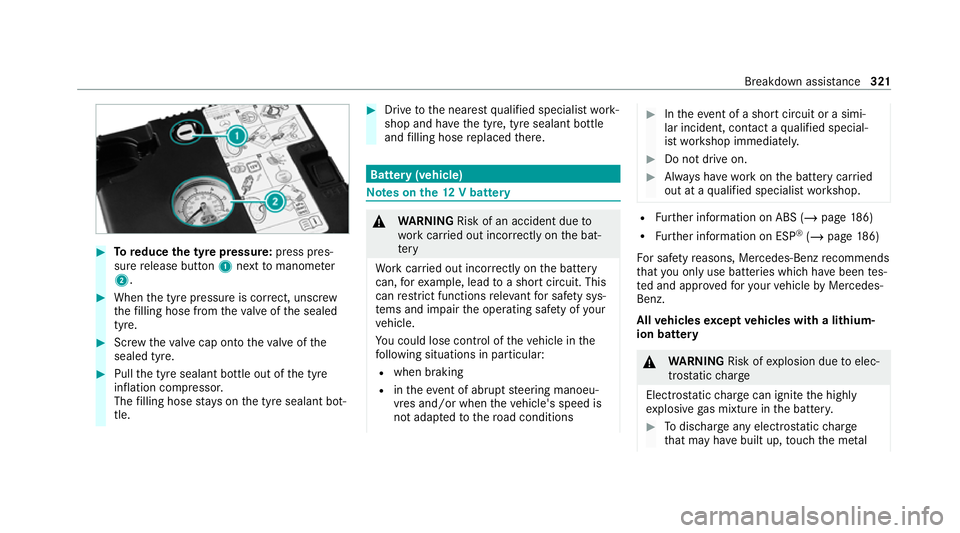
Toreduce the tyre pressure: press pres‐
su re re lease button 1next tomanome ter
2 . #
When the tyre pressure is cor rect, unscr ew
th efilling hose from theva lve of the sealed
tyre. #
Screw theva lve cap onto theva lve of the
sealed tyre. #
Pull the tyre sealant bottle out of the tyre
inflation compressor.
The filling hose stay s on the tyre sealant bot‐
tle. #
Drive tothe nearest qualified specialist work‐
shop and ha vethe tyre, tyre sealant bottle
and filling hose replaced there. Batte
ry(vehicle) Note
s onthe12 V battery &
WARNING Risk of an accident due to
wo rkcar ried out incor rectly on the bat‐
te ry
Wo rkcar ried out incor rectly on the battery
can, forex ample, lead toa short circuit. This
can restrict functions releva nt for saf ety sys‐
te ms and impair the operating saf ety of your
ve hicle.
Yo u could lose cont rol of theve hicle in the
fo llowing situations in particular:
R when braking
R intheeve nt of ab rupt steering manoeu‐
vres and/or when theve hicle's speed is
not adap tedto thero ad conditions #
Intheeve nt of a sho rtcircuit or a simi‐
lar incident, contact a qualified special‐
ist workshop immediately. #
Do not drive on. #
Alw ays ha vewo rkon the battery car ried
out at a qualified specialist workshop. R
Further information on ABS (/ page186)
R Further information on ESP ®
(/ page 186)
Fo r saf etyre asons, Mercedes-Benz recommends
th at you on lyuse bat teries which ha vebeen tes‐
te d and appr ovedfo ryo ur vehicle byMercedes-
Benz.
All vehicles except vehicles with a lithium-
ion battery &
WARNING Risk ofexplosion due toelec‐
tros tatic charge
Electros tatic charge can igni tethe highly
ex plosive gas mixture in the batter y. #
Todischar geany electros tatic charge
th at may ha vebuilt up, touch the me tal Breakdown assis
tance 321