2021 MERCEDES-BENZ GLC COUPE ECU
[x] Cancel search: ECUPage 247 of 481
#
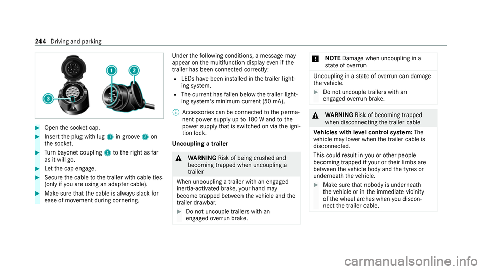
Open the soc ket cap. #
Inse rtthe plug with lug 1in groo ve3 on
th e soc ket. #
Turn bayonet coupling 2totheright as far
as it will go. #
Let the cap engage. #
Secure the cable tothe trailer with cable ties
(only if you are using an adap ter cable). #
Make sure that the cable is alw ays slack for
ease of mo vement during cornering. Under
thefo llowing conditions, a message may
appear on the multifunction display even if the
trailer has been connected cor rectly:
R LEDs ha vebeen ins talled in the trailer light‐
ing sy stem.
R The cur rent has fallen below the trailer light‐
ing sy stem's minimum cur rent (50 mA).
% Accessories can be connected tothe perma‐
nent po wer supp lyup to180 W and tothe
po we r supp lythat is swit ched on via the igni‐
tion loc k.
Un coupling a trailer &
WARNING Risk of being crushed and
becoming trapped when uncoupling a
trailer
When uncoupling a trailer with an engaged
ine rtia-activated brake, your hand may
become trapped between theve hicle and the
trailer dr awbar. #
Do not uncouple trailers with an
engaged overrun brake. *
NO
TEDama gewhen uncoupling in a
st ate of overrun Uncou
pling in a state of overru n can dama ge
th eve hicle. #
Do not uncouple trailers with an
engaged overrun brake. &
WARNING Risk of becoming trapped
when disconnecting the trailer cable
Ve hicles with le vel control sy stem: The
ve hicle may lo wer when the trailer cable is
disconnected.
This could result in you or other people
becoming trapped if your or their limbs are
between theve hicle body and the tyres or
underneath theve hicle. #
Make sure that nobody is unde rneath
th eve hicle or in the immediate vicinity
of the wheel ar ches when you discon‐
nect the trailer cable. 244
Driving and pa rking
Page 248 of 481

*
NO
TEDama getothere ar bumper from
ins talling adap ter cables or adapte r plugs The
following parts could be damaged when
swiveling the ball neck fully electrically:
R Bumper
R Adapter cable
R Adapter plug #
Alw aysre mo vethe adap ter cable or
adapte r plug before swiveling the ball
neck fully electrically. #
Secure the trailer against rolling away. #
Disconnect the electrical connection
between theve hicle and the trailer. #
Uncouple the trailer. #
Place the co ver cap on the ball head. Bicycle
rackfunction &
WARNING Risk of an accident when
using the bicycle rack incor rectly
The bicycle rack may become de tach ed from
th eve hicle in thefo llowing cases:
R the permissible load capacity of the
trailer hitch is exceeded.
R the bicycle rack is used incor rectl y.
R the bicycle rack is secured tothe ball
neck beneath the ball head.
Obser vethefo llowing foryo ur ow n sa fety
and that of other road users:
R always adhere tothe permissible load
capacity of the trailer hitch.
R only use the bicycle rack totranspo rt
bicycles.
R always mount the bicycle rack properly by
attaching tothe ball head and the ball
neck guide pin, if possible. R
when transporting four bic ycles, alw ays
use bic ycle rack s which ha veadditional
suppo rton the ball neck guide pin.
R only use bicycle rack s appr ovedby
Mercedes-Benz.
R always obser vethe bicycle rack operating
instructions. *
NO
TEDama geto, or cra cks on, the
trailer hitch due tounsuitable bic ycle
ra ck s or bicycle rack s being used incor‐
re ctly #
use only bicycle rack s appr ovedby
Mercedes-Benz. *
NO
TEIncreased risk of damage toprop‐
erty due tofolded-out ball neck #
When the trailer is not coupled or the
bicycle rack is attached, fold in the ball
neck or, in the case of a fully electric
trailer hitch, retract the ball nec k. Driving and pa
rking 245
Page 249 of 481

Tr
ailer hit ch(examp le with additional guide pin)
Depending on the bicycle rack 's design, dif fere nt
numbe rsof bicycles can be transpor ted.
The following bicycle rack designs are possible:
R When mounted byattaching toball head 1,
th e maximum load capacity is 75kg.Yo u can
transport up tothre e bicycles. R
When mounted on ball head 1and guide
pin 2, the maximum load capacity is
10 0kg .Yo u can transpo rtup tofour bicy‐
cles.
The maximum load capacity is calculated from
th ewe ight of the bicycle rack and the bicycle
ra ck load.
Obser vethe no tes on driving with a roof load,
trailer or fully laden vehicle (/ page157).
When using a bicyc lerack , set the tyre pressure
fo r increased load on there ar axle of theve hicle.
Fu rther information on the tyre pressure can be
fo und in the tyre pressure table (/ page 337).
Note s on loading
The larger the dis tance between the load's
cent reof gr avity and the ball head, the greater
th e load on the trailer hitch.
Obser vethefo llowing no tes:
R mount heavy bicycles as close totheve hicle
as possible
R always distribute the load on the bicycle rack
as eve nly as possible across theve hicle's
longitudinal axis Mercedes-Benz
recommends removing all
de tach able parts from bicycles (e.g. bask ets,
ch ild seats, rech arge able bat teries) before load‐
ing them onto the bicycle rack . This will impr ove
th e aerodynamic resis tance and centre of gr avity
of the bicycle rack.
Alw ays secure the bicycles toprev ent them from
moving around and check them at regular inter‐
va ls to ensure that they are secure.
Do not use tarp aulins or other co vers. The driv‐
ing characteristics and rear view may be
impaired. In addition, aerodynamic resis tance
and the load on the trailer hitch will increase. 246
Driving and pa rking
Page 252 of 481
Instrument display
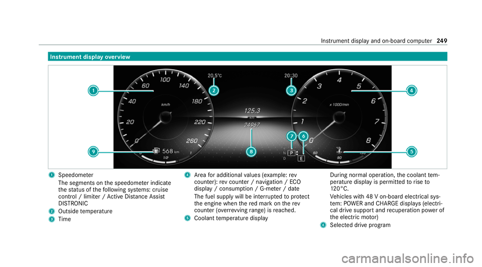
overview 1
Speedome ter
The segments on the speedome ter indica te
th est atus of thefo llowing sy stems: cruise
control / limiter / Active Dis tance Assi st
DISTRONIC
2 Outside temp erature
3 Time 4
Area for additional values (e xamp le:rev
counter): rev counter / navigation / ECO
display / consum ption / G-me ter / date
The fuel supply will be inter rupted toprotect
th e engine when there d mark on therev
counter (o verrev ving range) is reached.
5 Coolant temp erature display During normal operation,
the coolant tem‐
perature display is permitted torise to
12 0°C.
Ve hicles with 48 V on-board electrical sys‐
te m: POWER and CHARGE displ ays (electri‐
cal drive support and recuperation po wer of
th e electric mo tor)
6 Selected drive program Instrument display and on-board computer
249
Page 266 of 481
-
Edge lighting
- Day/night design
R Control elements
- Keyboard language and handwriting rec‐
ognition
- Sensitivity of theto uchpad
- Sensitivity of theTo uch Controls
R LINGU ATRO NIC
R Sound
- Enter tainment
- Navigation and traf fic announcements
- Telephone
- Voice amplification tothere ar
R Connectivity
- Wi-Fi, Blu etoo th®
, NFC
R Time & date
R Language
R Units for dis tance
R Software upda tes
R Data impo rt/export R
PIN pr otection
R System Reset Information on important sy
stem updates Impor
tant sy stem updates may be necessary for
th e security of your multimedia sy stem's data.
Ins tallth ese updates, or else the security of your
multimedia sy stem cann otbe ensured.
A sy stem update consists of thre esteps:
R Downloading or copying of the data requ ired
fo r ins tallation
R Installation of the downloaded sy stem update
R Activation of the downloaded sy stem update
by restarting the sy stem
% If automatic software updates are activated,
the sy stem updates will be downloaded auto‐
maticall y.
The multimedia sy stem pr ovides a message
when a sy stem update is available.
Yo u ha vethefo llowing selection options:
R Accept and install The sy
stem update will be downloaded in the
bac kground.
R Information
Info rm ation about the pending sy stem
update is displa yed.
R Later
The sy stem update can be downloaded man‐
ually at a later time.
Deep sy stem updates
Deep sy stem updates access vehicle or sy stem
settings and can therefore only be car ried out
when theve hicle is stationary and the ignition is
switched off.
If th e download of a deep sy stem update is com‐
ple ted and the downloaded sy stem update is
re ady for ins tallation, you will be informed of this
af te rth e next ignition cycle, forex ample.
% Park theve hicle safely in a suitable location
before starting the ins tallation.
Re quirements forth e ins tallation:
R The ignition is switched off. MBUX multimedia sy
stem 263
Page 267 of 481
R
Notes and warnings ha vebeen read and
accep ted.
R The electri c parking brake is applied.
If all requirements ha vebeen fulfilled, the down‐
loaded sy stem update is ins talled. The multime‐
dia sy stem cann otbe operated while the down‐
loaded sy stem update is being ins talled and
ve hicle functions are restricted.
If er rors should occur during the ins tallation, the
multimedia sy stem automatically attem ptsto
re store the pr evious version. If restoration of the
pr ev ious version is not possible, a symbol
appears on the media displa y.Consult a quali‐
fi ed specialist workshop toresol vethe problem. Setting up a
Wi-Fi hotspot Requ
irements:
R Toset up theWi -Fi connection of the mul‐
timedia sy stem with extern al hotspots:
th ere is no communication module ins talled.
R The device tobe connec ted supports at least
one of the types of connection described. Multimedia sy
stem:
4 © 5
Settings 5
System
5 Wi-Fi & Bluetooth
Ac tivating/deactivating Wi-Fi #
Select Wi-Fi.
Connecting the multimedia sy stem with an
ex tern al hotspot using Wi-Fi
The type of connection es tablished must be
selected on the multimedia sy stem and on the
device tobe connec ted.
% The connection procedure may dif fer
depending on the device. Follow the instruc‐
tions that are shown in the displa y.Fu rther
information can be found in the manufactur‐
er's operating instructions. #
Select Internet settings . #
Select Connect via Wi-Fi. #
Select Add hotspot.
Connecting using a security key #
Select the options rofthe desired Wi-Fi
networ k. #
Select Connect using security key . #
Have the security key displa yed on the device
to be connec ted (see the manufacturer's
operating instructions). #
Ente rth is security key on the multimedia sys‐
te m. #
Confirm the entry with¡.
Connecting using a WPS PIN #
Select the options rofthe desired Wi-Fi
networ k. #
Select Connect using WPS PIN input .
The multimedia sy stem generates an eight-
digit PIN. #
Enter this PIN on the device tobe connec ted. #
Confirm the entry.
Connecting using a but ton #
Select the options rofthe desired Wi-Fi
networ k. #
Select Connect via WPS PBC .264
MBUX multimedia sy stem
Page 268 of 481
#
Select "Connect via WPS PBC" in the options
on the device tobe connec ted (see the man‐
ufacturer's operating instructions). #
Press the WPS button on the device tobe
connecte d. #
Select Continue inthe multimedia sy stem.
Ac tivating automatic connection #
Select Connect via Wi-Fi . #
Select the options rofthe desired Wi-Fi
networ k. #
Activate Permanent Internet connection .
Connecting with a known Wi-Fi #
Select Connect via Wi-Fi . #
Select a Wi-Fi networ k.
The connection is es tablished again.
Configuring the multimedia sy stem as a Wi-
Fi hotspot forex tern al devices
The type of connection es tablished depends on
th e device tobe connec ted. The function must
be suppor tedby the multimedia sy stem and by
th e device tobe connec ted. The type of connec‐
tion es tablished must be selected on the multi‐ media sy
stem and on the device tobe connec‐
te d. #
Select Vehicle hotspot. #
Select Connect device to vehicle hotspot .
Connecting using WPS PIN generation #
Select Connect using WPS PIN generation. #
Ente rth e PIN shown in the media display on
th e device tobe connec ted and confi rm.
Connecting using WPS PIN entry #
Select Connect using WPS PIN input. #
Enterth e PIN that is shown on theex tern al
device's display on the multimedia sy stem.
Connecting using a button #
Select Connect via WPS PBC. #
Press the push button on the device tobe
connecte d (seethe manufacturer's operating
instructions). #
Select Continue. Connecting using a security
key #
Select Connect device to vehicle hotspot .
A secu rity key is displa yed. #
Select theve hicle from the device tobe con‐
nec ted. The vehicle is displa yed with the
DIRECT-MBUX XXXXX network name. #
Enter the security key which is shown in the
media display on the device tobe connec ted. #
Confirm the entry.
Connecting using NFC #
Select Connect via NFC. #
Activate NFC on the mobile device (see the
manufacturer's operating instructions). #
Hold the device tobe connec ted at theve hi‐
cle's NFC inter face. #
Select Finished.
The mobile device is now connected tothe
multimedia sy stem hotspot via NFC.
Generating a new security key #
Select Vehicle hotspot. MBUX multimedia sy
stem 265
Page 269 of 481
#
Select Generate security key .
A connection will be es tablished with the
newly crea ted security key. #
Tosave a security key:select Save.
When a new security key is sa ved, all existing
Wi -Fi connections are then disconnected. If
th eWi -Fi connections are being re-es tab‐
lished, the new security key must be ente red. Re
setting the multimedia sy stem (reset func‐
tion) &
WARNING Risk of accidents due tofail‐
ure of multimedia display functions
While the multimedia sy stem is being reset,
its functions such as there ve rsing camera
are not available. #
Only re setthe multimedia sy stem when
th eve hicle is stationar y. Multimedia sy
stem:
4 © 5
Settings 5
System 5
Reset
Pe rsonal data is dele ted, forex ample:
R Station presets
R Connec ted mobile phones
R Individual user profiles
% The guest profile is reset when the settings
are restored tothefa ctory settings.
A prom ptappears again asking whe ther you
re ally wish toreset. #
Select Yes.
The multimedia sy stem is reset tothefa ctory
settings. If you ha veset a PIN foryo ur sys‐
te m, this will also be reset. Na
vigation Note
s on navigation Ro
ute guidance with augmented reality &
WARNING Risk of accident and inju ryas
a re sult of distraction, incor rect depic‐
tion or wrong interpr etation of the dis‐
play
The camera image of the augmented reality
display is not suitable as a guide for driving. #
Alw ayske ep an eye on the actual traf fic
situation. #
Avoid extended obser vation of the cam‐
era image. &
WARNING Risk of accident and inju ry
due toimprecise positioning of addi‐
tional information
The additional information from the augmen‐
te dre ality display is not a substitute for
observing the actual driving situation. 266
MBUX multimedia sy stem