Page 409 of 577
4MA
4MA
TIC v
TIC v ehicles/v
ehicles/v ehicles wit
ehicles wit h aut
h aut omatic tr
omatic tr ans-
ans-
mission
mission #
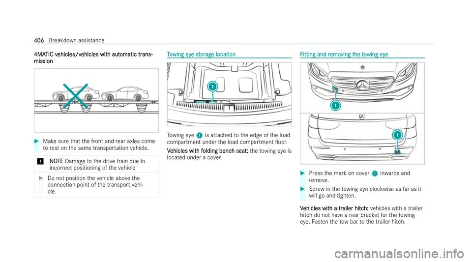
Make sure that the front and rear axles come
to rest on the same transpor tation vehicle.
* N
NOOTE
TE Damage tothe drive train due to
incor rect positioning of theve hicle #
Do not position theve hicle abo vethe
connection point of the transport vehi-
cle. T
T
o
o wing ey
wing eye st
e st or
or ag
ag e location
e location To
wing eye1 is attached tothe edge of the load
compartment under the load compartment �0oor.
V
V ehicles wit
ehicles wit h f
h folding benc
olding benc h seat
h seat:
: th eto wing eye is
located under a co ver. F
F
itting and r
itting and r emo
emoving t
ving t heto
he towing eye
wing eye #
Press the mark on co ver1 inwa rds and
re mo ve. #
Screw intheto wing eye clockwise as far as it
will go and tighten.
V
V ehicles wit
ehicles wit h a tr
h a trailer hitc
ailer hitc h:
h:vehicles with a trailer
hitch do not ha veare ar brac ketfo rth eto wing
ey e. Fasten theto w bar tothe trailer hitch. 406
406
Breakdown assistance
Page 411 of 577
#
When closing the fuse box, make sure
th at the seal of the lid is positioned cor-
re ctly on the fuse box. If
th e ne wlyinser ted fuse also blo ws, ha vethe
cause traced and recti�/ed at a quali�/ed specialist
wo rkshop.
Ensure thefo llowing before replacing a fuse:
R The vehicle is secured against rolling away.
R All electrical consume rsare switched o�..
R theve hicle is switched o�..
The elect rical fuses are located in various fuse
bo xes:
R Fuse box in the engine compartment on the
driver's side (/ page 408)
R Fuse box on the driver's side of the cockpit
(/ page 409)
R Fuse box in the front passenger foot we ll
(/ page 409)
R Fuse box in the load compartment on the
ri ght-hand side of theve hicle, when vie wed in
th e direction of tr avel (/ page 409) Opening and closing t
Opening and closing t
he fuse bo
he fuse box in t
x in the engine
he engine
com
com par
partment
tment R R
eq eq uir
uir ements:
ements:
R A dry clo thand a scr ewdriver are available.
Obser vethe no tes on elect rical fuses
(/ page 407).
Opening
Opening &
W
WARNING
ARNING Risk of injury from using the
windscreen wipers when the bonnet is
open
If th e windscreen wipers start moving when
th e bonnet is open, you could be trapped by
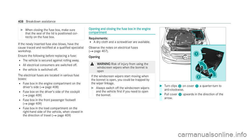
th e wiper linkage. #
Always switch o�. the windscreen wipers
and theve hicle �/r stifyo u need toopen
th e bonnet. #
Turn clips 2on co ver1 aqu arter-turn to
anti-clockwise. #
Pull co ver1 upwards in the direction of the
ar ro w. 408
408
Breakdown assistance
Page 412 of 577
#
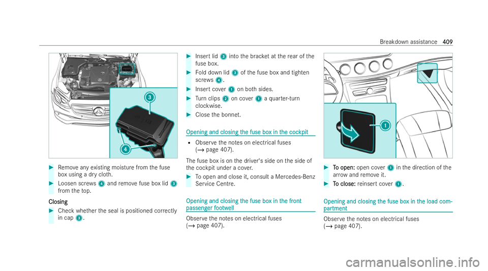
Remo veany existing moisture from the fuse
box using a dry clo th. #
Loosen scr ews4 and remo vefuse box lid 3
from theto p.
Closing
Closing #
Check whe ther the seal is positioned cor rectly
in cap 3. #
Insert lid 3into the brac ket at there ar of the
fuse box. #
Fold down lid 3ofthe fuse box and tighten
scr ews4. #
Insert co ver1 on bo thsides. #
Turn clips 2on co ver1 aqu arter-turn
clockwise. #
Close the bonnet. Opening and closing t
Opening and closing t
he fuse bo
he fuse box in t
x in the coc
he coc kpit
kpit R
Obser vethe no tes on elect rical fuses
(/ page 407).
The fuse box is on the driver's side on the side of
th e cockpit under a co ver. #
Toopen and close it, consult a Mercedes-Benz
Service Centre. Opening and closing t
Opening and closing t
he fuse bo
he fuse box in t
x in the fr
he front
ont
passeng
passeng er f
er foo
ootw
twell
ell Obser
vethe no tes on elect rical fuses
(/ page 407). #
T To open: o open: open cover1 inthe direction of the
ar ro w and remo veit. #
T To close:
o close: reinsert co ver1. Opening and closing t Opening and closing t
he fuse bo
he fuse box in t
x in the load com-
he load com-
par
par tment
tment Obser
vethe no tes on elect rical fuses
(/ page 407). Breakdown assistance
409
409
Page 424 of 577
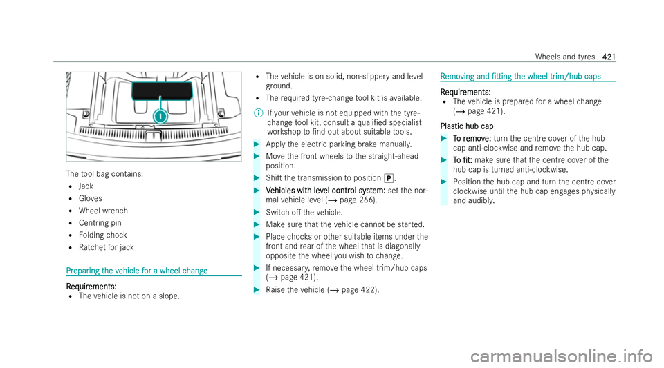
The
tool bag contains:
R Jack
R Gloves
R Wheel wrench
R Centring pin
R Folding chock
R Ratchet for jack Pr
Pr
epar
epar ing t
ing the v
he vehicle f
ehicle f or a wheel c
or a wheel c hange
hange R
R
eq
eq uir
uir ements:
ements:
R The vehicle is not on a slope. R
The vehicle is on solid, non-slippery and le vel
gr ound.
R The requ ired tyre-change tool kit is available.
% Ifyo ur vehicle is not equipped with the tyre-
ch ange tool kit, consult a quali�/ed specialist
wo rkshop to�/nd out about sui table tools. #
Apply the electric parking brake manuall y. #
Movethe front wheels tothe straight-ahead
position. #
Shi�T the transmission toposition j. #
V
Vehicles wit
ehicles wit h lev
h level contr
el contr ol syst
ol system:
em:setthe nor-
mal vehicle le vel (/ page 266). #
Switch o�. theve hicle. #
Make sure that theve hicle cann otbe star ted. #
Place choc ks orother suitable items under the
front and rear of the wheel that is diagonal ly
opposite the wheel you wish tochange. #
If necessar y,remo vethe wheel trim/hub caps
(/ page 421). #
Raise theve hicle (/ page 422). R
R
emo
emo ving and
ving and �/tting
�/ttingt
the wheel tr
he wheel tr im/hub caps
im/hub caps R R
eq eq uir
uir ements:
ements:
R The vehicle is prepared for a wheel change
(/ page 421).
Plas
Plas tic hub cap
tic hub cap #
T
To r
o r emov
emov e:
e:turn the centre co ver of the hub
cap anti-clockwise and remo vethe hub cap. #
T
To
o �/t:
�/t: make sure that the centre co ver of the
hub cap is turned anti-clockwise. #
Position the hub cap and turn the centre co ver
clockwise until the hub cap engages ph ysically
and audibl y. Wheels and tyres
421
421
Page 425 of 577
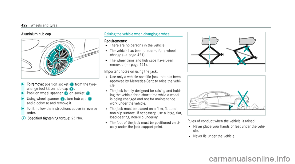
Aluminium hub cap
Aluminium hub cap
#
T
To r
o r emov
emov e:
e:position soc ket2 from the tyre-
ch ange tool kit on hub cap 1.#
Position wheel spanner 3on soc ket2. #
Using wheel spanner 3, turn hub cap1
anti-clockwise and remo veit. #
T To o �/t:
�/t: follow the inst ructions abo veinreve rse
order.
% Speci�/ed
Speci�/ed tight
tightening t
ening t orq
orque:ue: 25 Nm. R
R
aising t
aising t he v
he vehicle when c
ehicle when c hanging a wheel
hanging a wheel R R
eq
eq uir uir ements:
ements:
R There are no persons in theve hicle.
R The vehicle has been prepared for a wheel
ch ange (/ page 421).
R The wheel trims and hub caps ha vebeen
re mo ved (/ page 421).
Impor tant no tes on using the jack:
R Use only a vehicle-speci�/c jack that has been
appr ovedby Mercedes-Benz toraise theve hi-
cle.
R The jack is only designed forra ising and hold-
ing theve hicle for a short time while a wheel
is being changed and not for maintenance
wo rkunder theve hicle.
R The jack must be placed on a �/rm, �0at and
non-slip sur face. If necessar y,use a lar ge, �0at,
load-bearing, non-slip underla y.
R The foot ofthe jack must be positioned verti-
cally under the jack support point. Ru
les of conduct when theve hicle is raised:
R Never place your hands or feet under theve hi-
cle.
R Never lie under theve hicle. 422
422
Wheels and tyres
Page 427 of 577
#
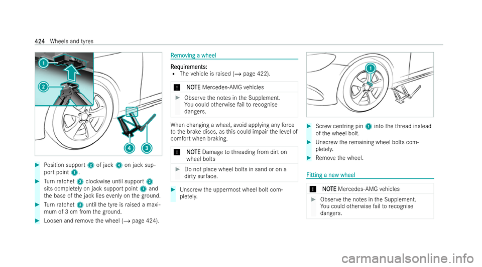
Position support 2of jack 4on jack sup-
port point 1. #
Turn ratchet 3clockwise until support 2
sits comple tely on jack support point 1and
th e base of the jack lies evenly on thegr ound. #
Turn ratchet 3until the tyre is raised a maxi-
mum of 3 cm from thegr ound. #
Loosen and remo vethe wheel (/ page 424). R
R
emo
emo ving a wheel
ving a wheel R R
eq eq uir
uir ements:
ements:
R The vehicle is raised (/ page 422).
* NO
NOTE
TEMercedes-AMG vehicles #
Obser vethe no tes in the Supplement.
Yo u could otherwise failto recognise
dangers. When
changing a wheel, avoid applying any force
to the brake discs, as this could impair the le vel of
comfort when braking.
* N
NOOTE
TE Damage tothre ading from dirt on
wheel bolts #
Do not place wheel bolts in sand or on a
dirty sur face. #
Unscr ewthe uppermost wheel bolt com-
ple tely. #
Screw cent ring pin 1into theth re ad ins tead
of the wheel bolt. #
Unscr ewthere maining wheel bolts com-
ple tely. #
Remo vethe wheel. F F
itting a ne
itting a ne w wheel
w wheel *
N NOOTE TE Mercedes-AMG vehicles #
Obser vethe no tes in the Supplement.
Yo u could otherwise failto recognise
dangers. 424 424
Wheels and tyres
Page 428 of 577
&
W
W ARNI NG
ARNI NGRisk of accident from losing a
wheel
Oiled or greased wheel bolts can cause the
wheel bolts tocome loose, as too can dam-
aged wheel bolts or wheel hub thre ads. #
Never oil or grease theth re ads. #
Intheev ent of damage totheth re ads,
contact a quali�/ed specialist workshop
immediatel y. #
Have the damaged wheel bolts or dam-
aged hub thre ads replaced. #
Do not continue driving. #
Obser vethe information on thech oice of tyres
(/ page 416).
Fo r tyres with a speci�/ed direction of rotation, an
ar ro w on the side wall of the tyre indicates the
cor rect direction of rotation. Obser vethe direc-
tion of rotation when �/tting. #
Slide the wheel tobe mounted onto the cen-
tring pin and push it on. &
W
WARNING
ARNING Risk of injury from tightening
wheel bolts and nuts
If yo u tighten the wheel bolts or wheel nuts
when theve hicle is raised, the jack could tip. #
Only tighten wheel bolts or wheel nuts
when theve hicle is on thegr ound. #
Be sure toobser vethe inst ructions and saf ety
no tes on "Changing a wheel" (/ page 416). #
For saf etyre asons, only use wheel bolts which
ha ve been appr oved byMercedes-Benz and
fo rth e wheel in question. #
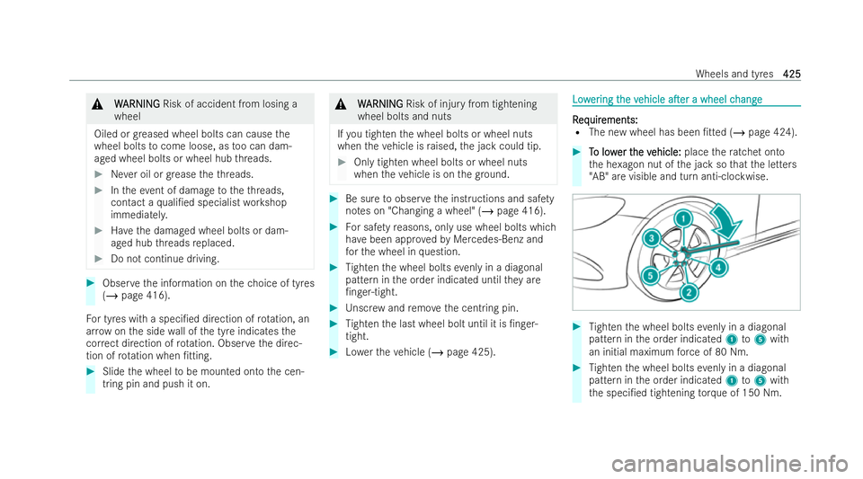
Tighten the wheel bolts evenly in a diagonal
pattern in the order indicated until they are
�/nger-tight. #
Unscr ewand remo vethe centring pin. #
Tighten the last wheel bolt until it is �/n ger-
tight. #
Lowe rth eve hicle (/ page 425). Low Low
er
ering t
ing t he v
he vehicle
ehicle a�Ter
a�Tera wheel c
a wheel c hange
hange R
R
eq
eq uir
uir ements:
ements:
R The new wheel has been �/tted (/ page 424). #
T
To low
o low er t
er the v
he v ehicle:
ehicle: placethera tchet onto
th e he xagon nut of the jack so that the letters
"AB" are visible and turn anti-clockwise. #
Tighten the wheel bolts evenly in a diagonal
pattern in the order indicated 1to5 with
an initial maximum forc e of 80 Nm. #
Tighten the wheel bolts evenly in a diagonal
pattern in the order indicated 1to5 with
th e speci�/ed tightening torque of 150 Nm. Wheels and tyres
425
425
Page 458 of 577
Displa
Displa
y messag
y messag es P
es Possible causes/conseq
ossible causes/consequences and uences andM
MSolutions
Solutions
Á
Key not detected (white dis-
play message) *T
hekey is cur rently unde tected. #
Change the location of theke y in theve hicle. #
Ifth eke y is still not recognised, place it in the slot for starting with theke y (/ page 178).
Á Key not detected (red dis-
play message) *T
hekey cann otbe de tected and may no longer be in theve hicle.
The key is no lon ger in theve hicle and you switch o�. theve hicle:
R You can no longer start theve hicle.
R You cannot centrally lock theve hicle. #
Ensu rethat theke y is in theve hicle.
If th eke y de tection function has a malfunction due toa st rong radio signal source: #
Stop theve hicle immediately in accordance with the tra�1c conditions. #
Place theke y in the slot for starting the engine with theke y (/ page 178).
Á Key being initialised Please
wait *T
hevehicle is processing in order to teach in the new key. #
Wait until processing is comple te. Display messages and
warning/indicator lamps
455
455