Page 10 of 533

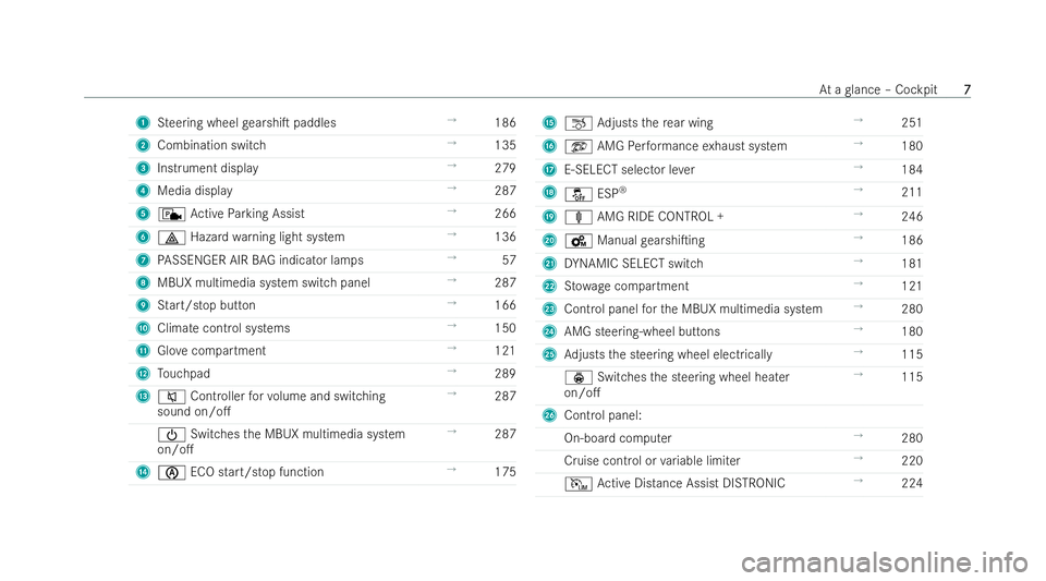
1
Steering wheel gearshi�T paddles →
186
2 Combination switch →
135
3 Instrument displ ay →
279
4 Media display →
287
5 c Active Parking Assist →
266
6 £ Hazard warning light system →
136
7 PASSENGER AIR BAG indicator la mps→
57
8 MBUX multimedia system switch panel →
287
9 Start/stop but ton →
166
A Climate control systems →
150
B Glovecompartment →
121
C Touchpad →
289
D 8 Controller forvo lume and switching
sound on/o�. →
287
Ü Switches the MBUX multimedia system
on/o�. →
287
E è ECO start/s top function →
175 F
~ Adjusts there ar wing →
251
G ö AMGPerformance exhaust system →
180
H E-SELECT selector le ver →
184
I å ESP®
→
211
J ä AMG RIDE CONTROL + →
246
K B Manual gearshi�Ting →
186
L DYNAMIC SELECT switch →
181
M Stow age compartment →
121
N Control panel forth e MBUX multimedia system →
280
O AMG steering-wheel buttons →
180
P Adjusts the steering wheel electrically →
115
ý Switches the steering wheel heater
on/o�. →
115
Q Control panel:
On-board computer →
280
Cruise control or variable limi ter →
220
I Active Distance Assist DISTRONIC →
224 At
a glance – Cockpit
7 7
Page 198 of 533

ch
arging or from auxiliary consumers that are
switched on. Further information on rech arge e�1-
ciency can be obtained at a quali�/ed specialist
wo rkshop. Se
Se
tting t
tting t he maximum per
he maximum per missible c
missible c har
harging cur-
ging cur-
r
r ent f
ent f or c
or char
harging at a mains soc ket
ging at a mains soc ket *
N
NO
OTE
TE Overloading the mains soc ket due
to excessive charging cur rent If
th ech arging cur rent is too high, the fuse
could be tripped or theex tern al mains supply
could overheat. #
Make sure that theex tern al mains supply
has been designed tohandle the set
ch arging cur rent. #
For saf etyre asons, only use thech arging
cable supplied with theve hicle or an
original Mercedes-Benz charging cable.
Mercedes-Benz thoroughly tests these
original charging cables forth eir suitabil-
ity for high-voltage charging of your vehi-
cle. Pur chase these parts at a Mercedes- Benz Service Centre and obtain advice
th
ere. #
Check the maximum charging cur rent
using thech arging capacity shown in the
Instrument Displ ay. The
charging cable supplied is set toa countr y-
speci�/c maximum charging cur rent value. When
ch arging abroad, the maximum value may exceed
th e permitted value forth at countr y. #
Before charging at a mains soc ket, ha vethe
maximum permissible charging cur rent forthe
re leva nt mains soc ket or the building inspec-
te dby aqu ali�/ed elect rician. #
When abroad, obser vethe count ry-speci�/c
la ws when charging.
If yo u ha vequestions concerning thech arging
cur rent or if there is a malfunction, please contact
a quali�/ed specialist workshop. Ov Ov
er
ervie
vie w of t
w of t he c
he char
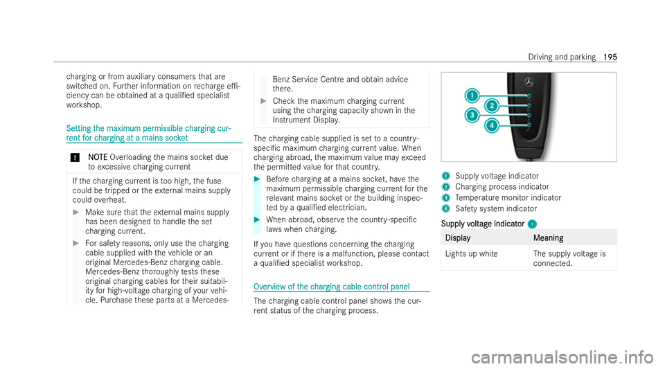
harging cable contr
ging cable contr ol panel
ol panel The
charging cable cont rol panel sho ws the cur-
re nt status of thech arging process. 1
Supply voltage indicator
2 Charging process indicator
3 Temp erature monitor indicator
4 Safety sy stem indicator
Suppl
Suppl y v
y volt
oltag
age indicat
e indicat or
or1
1 Display
Display
Meaning
Meaning
Lights up whit eThe supplyvoltage is
connected. Driving and parking
195
195
Page 283 of 533

The fuel supply will be inter
rupted toprotect
th e engine when there d mark on therev
counter (o verrev ving range) is reached.
7 Gear displ ay
8 Coolant temp erature display
The coolant temp erature display is permitted
to rise to120°C during normal operation.
Ve hicles with 48 V on-board elect rical system:
POWER and CHARGE displa ys(electrical drive
support and recuperation po wer of the elec-
tric mo tor)
Plug-in hybrid: cur rent state of charge ofthe
high- voltage battery
9 Selected drive prog ram
A Selected transmission position
B Centre display area of the inst rument display
(e xamp le: standard display for a trip): assis-
ta nce / telephone / navigation / trip / per-
fo rm ance / media / radio / styles and dis-
pla ys/ service / settings for head-up display
Plug-in hybrid: Powe r me ter
C Fuel le vel and fuel �/ller �0ap location indicator Ov
Ov
er
ervie
vie w of butt
w of butt ons on t
ons on the st
he steer
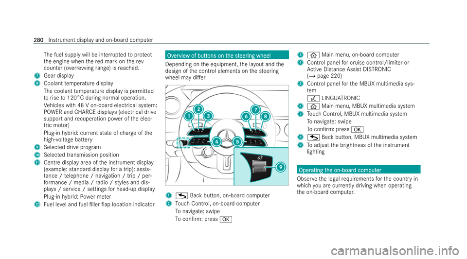
eer ing wheel
ing wheel
Depending on the equipment, the la yout and the
design of the control elements on the steering
wheel may di�.er. 1
G Back button, on-board computer
2 Touch Control, on-board computer
To navigate: swipe
To con�/rm: press a 3
ò Main menu, on-board computer
4 Cont rol panel for cruise control/limiter or
Ac tive Distance Assist DISTRONIC
(/ page 220)
5 Control panel forth e MBUX multimedia sys-
tem
£ LINGU ATRO NIC
6 ò Main menu, MBUX multimedia system
7 Touch Control, MBUX multimedia system
To navigate: swipe
To con�/rm: press a
8 G Back button, MBUX multimedia system
9 Toadjust the brightness of the inst rument
lighting Oper Oper
ating t
ating t he on-boar
he on-boar d com
d comput
puter
er
Obser vethe legal requ irements forth e country in
which you are cur rently driving when ope rating
th e on-board computer. 280
280
Instrument display and on-board computer