2021 MAZDA MODEL CX-30 camera
[x] Cancel search: cameraPage 313 of 594

Consult an Authorized Mazda Dealer
for repair, painting, or replacement
of the front/rear camera, front
bumper, liftgate and door mirrors.
Heed the following cautions to
assure that the 360°View Monitor
operates normally.
Do not modify the vehicle
suspensions or lower/raise the
vehicle body, or both.
Always use tires of the
specified
type and size for the front and rear
wheels. Consult an Authorized
Mazda Dealer for tire replacement.
When the display is cold, images
may leave trails or the screen might
be darker than usual, making it
difficult to check the vehicle
surroundings. Always confirm the
safety at the front and around the
vehicle visually when driving.
The method for parking/stopping
the vehicle using the 360°View
Monitor differs depending on the
road circumstances/conditions and
the vehicle conditions. When and
how much you turn the steering
wheel will differ depending on the
situation, , therefore always check
the vehicle surroundings directly with
your eyes while using the system.
Also, before using the system, always
make sure that the vehicle can be
parked/stopped in the parking/
stopping space.
NOTE
If there are water droplets, snow, or
mud on the camera lens, wipe it off
using a soft cloth. If the camera lens
is especially dirty, wash it off with
mild detergent.
If the camera lens is touched or there
is any dirt on it, it could affect the
screen image. Wipe the lens using a
soft cloth.
If the area where the camera is
installed, such as the front bumper,
liftgate or door mirrors, has been
damaged in a vehicle accident, the
camera (position, installation angle)
may have shifted. Always consult an
Authorized Mazda Dealer to have
the vehicle inspected.
If the camera is subjected to
excessive changes in temperature
such as by pouring hot water on the
camera during cold weather, the
360°View Monitor may not operate
normally.
If the vehicle is driven during cold
temperatures and the camera
temperature decreases, the top view
and the side view may become
u n c l ea r. H o we v e r, t h i s d o e s n o t
indicate a problem. If the vehicle is
stopped for a while and the camera
temperature increases, the top view
and the side view will return to the
normal condition.
If the battery voltage is low, the
screen might be temporarily difficult
to view, however, this does not
indicate a problem.
The 360°View Monitor has
limitations. Objects under the
bumper or near both ends of the
bumper cannot be displayed.
Obstructions above the upper image
range of the camera are not
displayed.
Under the following conditions, the
screen might be difficult to view,
however this does not indicate a
problem.
The temperature near the lens is
high/low.
When Driving
i-ACTIVSENSE
4-167
CX-30_8JP5-EA-20K_Edition1_new 2020-7-22 15:50:09
Page 314 of 594

Rainy conditions, water droplets
on the camera, or high humidity.
Mud or foreign matter near the
camera.
Extremely bright light such as
sunlight or headlights hitting the
camera lens directly.
The surroundings are illuminated
by vehicle lights, fluorescent lights,
or LED lights (display may flicker).
Extremely small dark or white dots
appear on the screen (dots mayflicker).
Because the 360°View Monitor
camera uses a special lens, the
distance displayed on the screendiffers from the actual distance.
Obstructions displayed on the screen
may appear differently than in
actuality. (Obstructions may appear
fallen, larger, or longer than they
actually are.)
Do not apply stickers to a camera or
the area around it. In addition, do
not install accessories or an
illuminated number/character
license plate to the area around a
camera. Otherwise, the camera may
not correctly display the surrounding
conditions.
Images displayed on the monitor
from the 360° view monitor camera
are reversed images (mirror images).
Free/open source software
information
This product includes free/open
sources. Information about the
licensing and source code is available
at the following URL.
https://www.denso.com/
global/en/opensource/svss/
mazda/
When Driving
i-ACTIVSENSE
4-168
CX-30_8JP5-EA-20K_Edition1_new 2020-7-22 15:50:09
Page 323 of 594

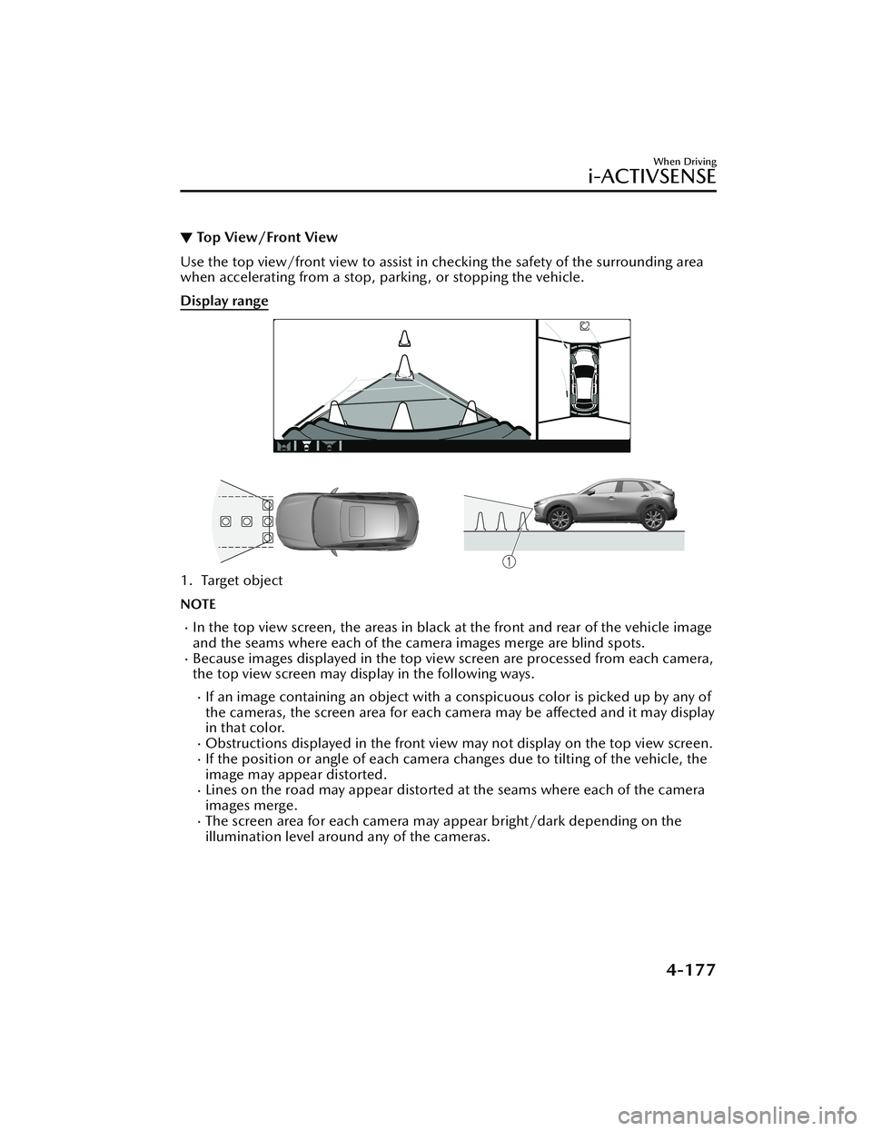
▼Top View/Front View
Use the top view/front view to assist in checking the safety of the surrounding area
when accelerating from a stop, parking , or stopping the vehicle.
Display range
1. Target object
NOTE
In the top view screen, the areas in black
at the front and rear of the vehicle image
and the seams where each of the camera images merge are blind spots.
Because images displayed in the top view screen are processed from each camera,
the top view screen may display in the following ways.
If an image containing an object with a conspicuous color is picked up by any of
the cameras, the screen area for each camera may be affected and it may display
in that color.
Obstructions displayed in the front view may not display on the top view screen.If the position or angle of each camera changes due to tilting of the vehicle, the
image may appear distorted.
Lines on the road may appear distorted at the seams where each of the camera
images merge.
The screen area for each camera may appear bright/dark depending on the
illumination level around any of the cameras.
When Driving
i-ACTIVSENSE
4-177
CX-30_8JP5-EA-20K_Edition1_new 2020-7-22 15:50:09
Page 326 of 594

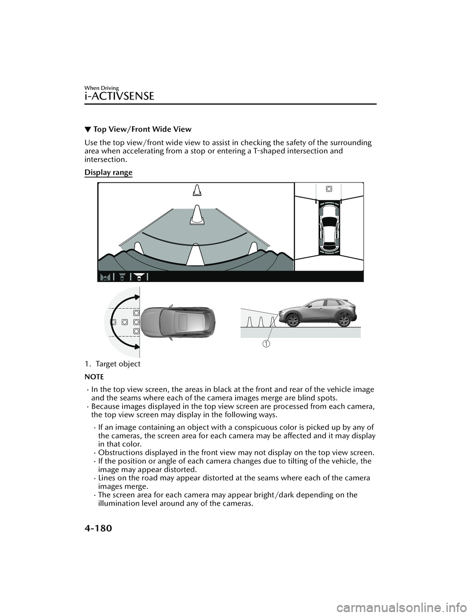
▼Top View/Front Wide View
Use the top view/front wide view to assist in checking the safety of the surrounding
area when accelerating from a stop or entering a T-shaped intersection and
intersection.
Display range
1. Target object
NOTE
In the top view screen, the areas in black at the front and rear of the vehicle image
and the seams where each of the camera images merge are blind spots.
Because images displayed in the top view screen are processed from each camera,
the top view screen may display in the following ways.
If an image containing an object with a conspicuous color is picked up by any of
the cameras, the screen area for each camera may be affected and it may display
in that color.
Obstructions displayed in the front view
may not display on the top view screen.If the position or angle of each camera changes due to tilting of the vehicle, the
image may appear distorted.
Lines on the road may appear distorted at the seams where each of the camera
images merge.
The screen area for each camera may appear bright/dark depending on the
illumination level around any of the cameras.
When Driving
i-ACTIVSENSE
4-180
CX-30_8JP5-EA-20K_Edition1_new 2020-7-22 15:50:09
Page 331 of 594

NOTE
Because there might be a difference between the image displayed on the screen
and the actual conditions, always check the safety of the surrounding area using
the mirrors and directly with your eyes when driving.
Even though the object displayed on the screen, such as a road curb or a division
line of a parking space, and the vehicle parallel guide lines appear parallel, they
may not actually be parallel.
▼ Top View/Rear View
Use the top view/rear view to assist in checking the safety of the surrounding area
when accelerating from a stop, parking , or stopping the vehicle.
Range of displayed screen image
1. Target object
NOTE
In the top view screen, the areas in black
at the front and rear of the vehicle image
and the seams where each of the camera images merge are blind spots.
Because images displayed in the top view screen are processed from each camera,
the top view screen may display in the following ways.
If an image containing an object with a conspicuous color is picked up by any of
the cameras, the screen area for each camera may be affected and it may display
in that color.
Obstructions displayed in the rear view may not display on the top view screen.If the position or angle of each camera changes due to tilting of the vehicle, the
image may appear distorted.
When Driving
i-ACTIVSENSE
4-185
CX-30_8JP5-EA-20K_Edition1_new 2020-7-22 15:50:09
Page 332 of 594

Lines on the road may appear distorted at the seams where each of the camera
images merge.
The screen area for each camera may appear bright/dark depending on the
illumination level around any of the cameras.
Viewing the screen
Display/Icon Content
(1) Tire icon Indicates the tire direction. Moves in conjunction with
the steering wheel operation.
(2) Projected vehicle path lines (yellow & red) Indicates the approximate projected path of the vehicle.
Moves in conjunction with the steering wheel operation.
a) Indicates the path where the edge of the rear bumper
is expected to travel.
b) Indicates the path where the outer side of the vehicle
is expected to travel.
(3) Extended vehicle width lines (blue) These guide lines indicate the approximate width of the vehicle.
(4) Projected vehicle path distance guide lines (yellow & red) These guide lines indicate the approximate distance to a
point measured from the rear of the vehicle (from the
end of the bumper).
The red line indicates the point about 0.5 m (19 in)
from the rear end of the bumper.
The yellow lines indicate the points about 1.0 m (39
in) and 2.0 m (78 in) from the rear end of the bumper.
NOTE
The setting can be changed so that th
e projected vehicle path lines are not
displayed.
Refer to the Settings section in the Mazda Connect Owner's Manual.
When Driving
i-ACTIVSENSE
4-186
CX-30_8JP5-EA-20K_Edition1_new 2020-7-22 15:50:09
Page 336 of 594

▼To p V i e w/ R e a r Wi d e Vi e w
Use the top view/rear wide view to assist
in checking the safety of the surrounding
area when accelerating from a stop, parking, or stopping the vehicle.
Range of displayed screen image
1. Target object
NOTE
In the top view screen, the areas in black at the front and rear of the vehicle image
and the seams where each of the camera images merge are blind spots.
Because images displayed in the top view screen are processed from each camera,
the top view screen may display in the following ways.
If an image containing an object with a conspicuous color is picked up by any of
the cameras, the screen area for each camera may be affected and it may display
in that color.
Obstructions displayed in the front view may not display on the top view screen.If the position or angle of each camera changes due to tilting of the vehicle, the
image may appear distorted.
Lines on the road may appear distorted at the seams where each of the camera
images merge.
The screen area for each camera may appear bright/dark depending on the
illumination level around any of the cameras.
When Driving
i-ACTIVSENSE
4-190
CX-30_8JP5-EA-20K_Edition1_new 2020-7-22 15:50:09
Page 338 of 594

▼Margin of Error Between Road Surface
on Screen and Actual Road Surface
There might be some margin of error between the road surface appearing on the
screen and the actual road surface. A margin of error in the perceived distance could
lead to an accident, therefore be aware of the following conditions which can more
easily produce errors in the perceived distance.
The vehicle tilts due to weight of passengers and cargo.
If the vehicle is tilted, obstructions picked up by a camera can appear farther or
closer than the actual distance from the vehicle.
Front camera
1. Obstruction
2. Margin of error
Side camera
1. Obstruction
2. Margin of error
Rear camera
1. Obstruction
2. Margin of error
When Driving
i-ACTIVSENSE
4-192
CX-30_8JP5-EA-20K_Edition1_new 2020-7-22 15:50:09