2021 Lexus IS350 Turn signal
[x] Cancel search: Turn signalPage 195 of 436
1954-5. Using the driving support systems
4
Driving
the location of the steering wheel in the vehicle (left side driver position versus right side
driver position.) If the vehicle is driven to a re gion where the overtaking lane is on a different
side from where the vehicle is normally driven, the vehicle may accelerate when the turn
signal lever is operated in the opposite direction to the overtaking lane (e.g., if the driver
normally operates the vehicle in a region where the overtaking lane is to the right but then
drives to a region where the overtaking lane is to the left, the vehicle may accelerate when
the right turn signal is activated).
Example of acceleration
When there are no longer any preceding vehicles driving slower than the set
speed
The system accelerates until the set speed is re ached. The system then returns to constant
speed cruising.
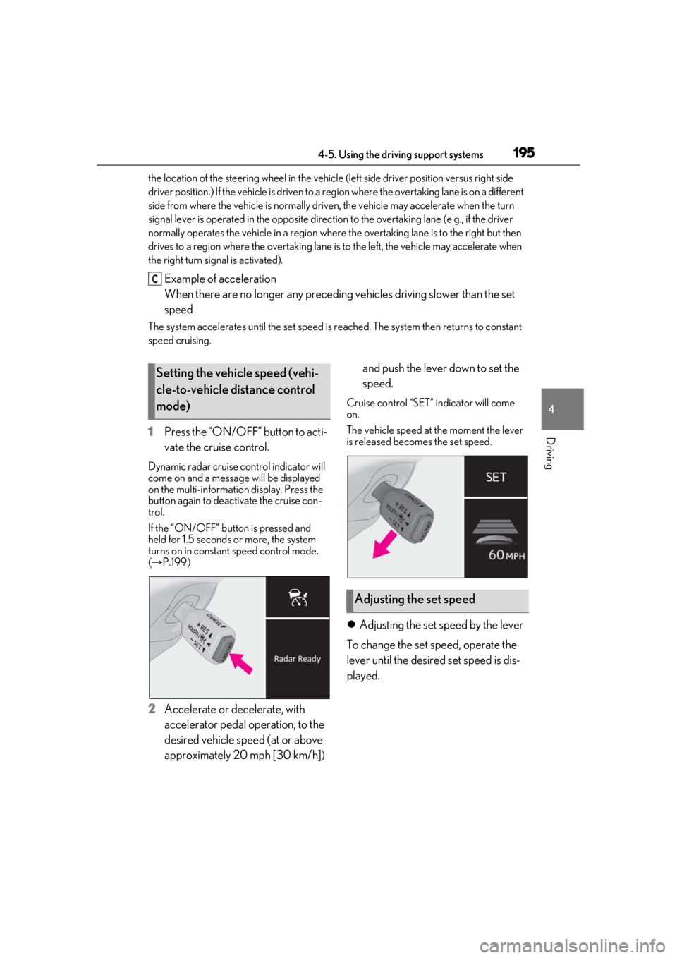
1 Press the “ON/OFF” button to acti-
vate the cruise control.
Dynamic radar cruise control indicator will
come on and a message will be displayed
on the multi-information display. Press the
button again to deactivate the cruise con-
trol.
If the “ON/OFF” button is pressed and
held for 1.5 seconds or more, the system
turns on in constant speed control mode.
( P.199)
2 Accelerate or decelerate, with
accelerator pedal operation, to the
desired vehicle speed (at or above
approximately 20 mph [30 km/h]) and push the lever down to set the
speed.
Cruise control “SET”
indicator will come
on.
The vehicle speed at the moment the lever
is released beco mes the set speed.
Adjusting the set speed by the lever
To change the set speed, operate the
lever until the desired set speed is dis-
played.
C
Setting the vehicle speed (vehi-
cle-to-vehicle distance control
mode)
Adjusting the set speed
Page 202 of 436
2024-5. Using the driving support systems
*:If equipped
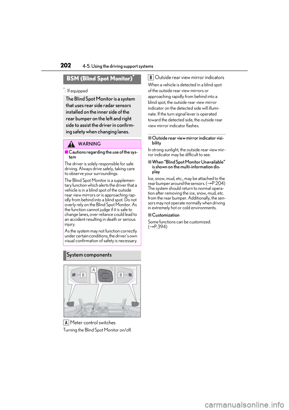
Meter control switches
Turning the Blind Spot Monitor on/off.
Outside rear view mirror indicators
When a vehicle is detected in a blind spot
of the outside rear view mirrors or
approaching rapidly from behind into a
blind spot, the outside rear view mirror
indicator on the detected side will illumi-
nate. If the turn signal lever is operated
toward the detected side, the outside rear
view mirror indicator flashes.
■Outside rear view mirror indicator visi-
bility
In strong sunlight, the outside rear view mir-
ror indicator may be difficult to see.
■When “Blind Spot Monitor Unavailable”
is shown on the multi-information dis-
play
Ice, snow, mud, etc., may be attached to the
rear bumper around the sensors. ( P.204)
The system should return to normal opera-
tion after removing the ice, snow, mud, etc.
from the rear bumper. Additionally, the sen-
sors may not operate normally when driving
in extremely hot or cold environments.
■Customization
Some functions can be customized.
( P.394)
BSM (Blind Spot Monitor)*
The Blind Spot Monitor is a system
that uses rear side radar sensors
installed on the inner side of the
rear bumper on the left and right
side to assist the driver in confirm-
ing safety when changing lanes.
WARNING
■Cautions regarding the use of the sys-
tem
The driver is solely responsible for safe
driving. Always driv e safely, taking care
to observe your surroundings.
The Blind Spot Monitor is a supplemen-
tary function which alerts the driver that a
vehicle is in a blind spot of the outside
rear view mirrors or is approaching rap-
idly from behind into a blind spot. Do not
overly rely on the Blind Spot Monitor. As
the function cannot judge if it is safe to
change lanes, over reliance could lead to
an accident resulting in death or serious
injury.
As the system may not function correctly
under certain conditions, the driver’s own
visual confirmation of safety is necessary.
System components
A
B
Page 277 of 436

2775-5. Using the other interior features
5
Interior features
3Within 1 minute of pressing the
HomeLink
® button, after the
garage door operation has
stopped, press the “Learn” or
“Smart” button on the garage door
opener motor. Within 5 seconds of
the establishment of 2-way com-
munication with the garage door
opener, both garage door opera-
tion indicators in the vehicle will
flash rapidly (green) and the light
on the garage door opener motor
will blink twice, indicating that
2-way communication is enabled.
■Reprogramming a single Home-
Link
® button
When the following procedure is per-
formed, buttons which already have
devices registered to them can be
overwritten:
1 With one hand, press and hold the
desired HomeLink
® button.
2 When the HomeLink
® indicator
starts flashing (orange), continue to
hold the HomeLink
® button and
perform “Programming Home-
Link
®” 1 (it takes 20 seconds for
the HomeLink
® indicator to start
flashing).
■Before programming
●Install a new battery in the transmitter.
●The battery side of the transmitter must
be pointed away from the HomeLink®.
Press the appropriate HomeLink®
button. The HomeLink
® indicator light
should turn on.
The status of the opening and closing
of a garage door is shown by the indi-
cators.
Opening
Closing
This function is only available if the garage
door opener motor used is a compatible
device. (To check device compatibility,
refer to www.homelink.com.)
The indicators can operate within
approximately 820 ft. (250 m) of the
garage door. However, if there are
obstructions between the garage door
and the vehicle, such as houses and
trees, feedback signals from the
garage door may not be received.
Operating HomeLink®
ColorStatus
Orange (flashing)Currently open-ing/closing
GreenOpening/closing has completed
Red (flashing)Feedback signals
cannot be received
A
B
Page 306 of 436

3066-3. Do-it-yourself maintenance
■Routine tire inflation pressure checks
The tire pressure warning system does not
replace routine tire inflation pressure
checks. Make sure to check tire inflation
pressure as part of your routine of daily
vehicle checks.
■Tire inflation pressure
●It may take a few minutes to display the
tire inflation pressure after the engine
switch is turned to IGNITION ON mode.
It may also take a few minutes to display
the tire inflation pres sure after inflation
pressure has been adjusted.
●Tire inflation pressure changes with tem-
perature. The displayed values may also
be different from the values measured
using a tire pressure gauge.
■Situations in which the tire pressure
warning system may not operate prop-
erly
●In the following cases, the tire pressure
warning system may not operate prop-
erly.
• If non-genuine Lexus wheels are used.
• If a tire has been repl aced with a tire that
is not an OE (Original Equipment) tire.
• If a tire has been repl aced with a tire that
is not of the specified size.
• If tire chains, etc. are installed.
• An auxiliary-supported run-flat tire is equipped.
• If a window tint that affects the radio wave signals is installed.
• If there is a lot of snow or ice on the vehi-
cle, particularly around the wheels or
wheel housings.
• If the tire inflation pressure is extremely
higher than the specified level.
• If tires not equipped with tire pressure warning valves and tr ansmitters are used.
• If the ID code on the tire pressure warn- ing valves and transmitters is not regis-
tered in the tire pressure warning
computer.
●Performance may be affected in the fol-
lowing situations.
• When driving near a TV tower, electric
power plant, gas station, radio station,
large display, airport or other facility that
generates strong radio waves or electri- cal noise
• When carrying a portable radio, cellular phone, cordless phone or other wireless
communication device
If tire position information is not correctly
displayed due to the radio wave conditions,
the display may be corrected by driving and
changing the radio wave conditions.
●When the vehicle is parked, the time
taken for the warning to start or go off
could be extended.
●When tire inflation pr essure declines rap-
idly for example when a tire has burst, the
warning may not function.
■Warning performance of the tire pres-
sure warning system
The warning of the tire pressure warning
system will change in accordance with driv-
ing conditions. For this reason, the system
may give a warning even if the tire pressure
does not reach a low enough level, or if the
pressure is higher than the pressure that
was adjusted to when the system was initial-
ized.
Page 322 of 436
3226-3. Do-it-yourself maintenance
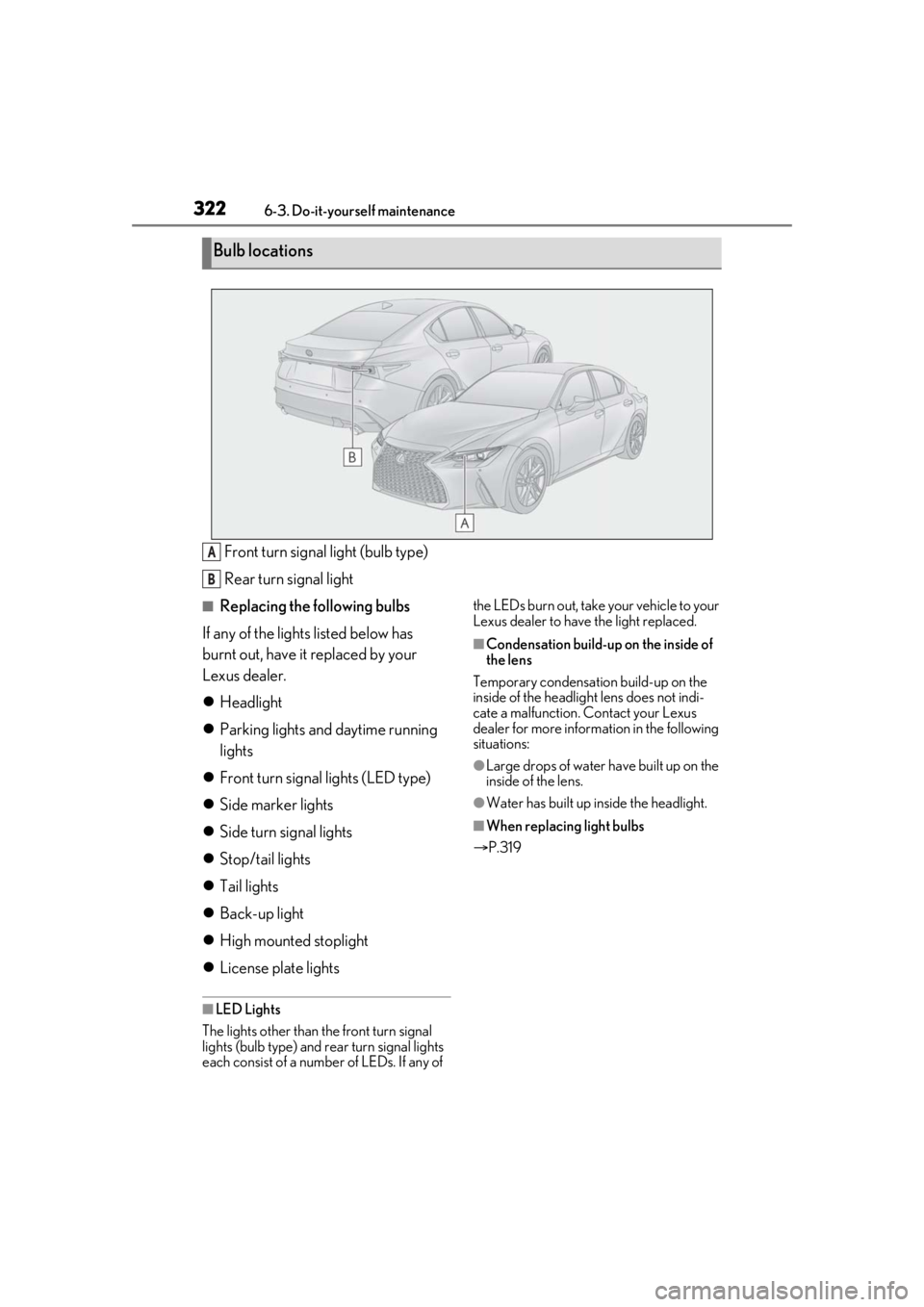
Front turn signal light (bulb type)
Rear turn signal light
■Replacing the following bulbs
If any of the lights listed below has
burnt out, have it replaced by your
Lexus dealer.
Headlight
Parking lights and daytime running
lights
Front turn signal lights (LED type)
Side marker lights
Side turn signal lights
Stop/tail lights
Tail lights
Back-up light
High mounted stoplight
License plate lights
■LED Lights
The lights other than the front turn signal
lights (bulb type) and rear turn signal lights
each consist of a number of LEDs. If any of the LEDs burn out, take your vehicle to your
Lexus dealer to have
the light replaced.
■Condensation build-up on the inside of
the lens
Temporary condensation build-up on the
inside of the headlight lens does not indi-
cate a malfunction. Contact your Lexus
dealer for more information in the following
situations:
●Large drops of water have built up on the
inside of the lens.
●Water has built up inside the headlight.
■When replacing light bulbs
P.319
Bulb locations
A
B
Page 323 of 436
3236-3. Do-it-yourself maintenance
6
Maintenance and care
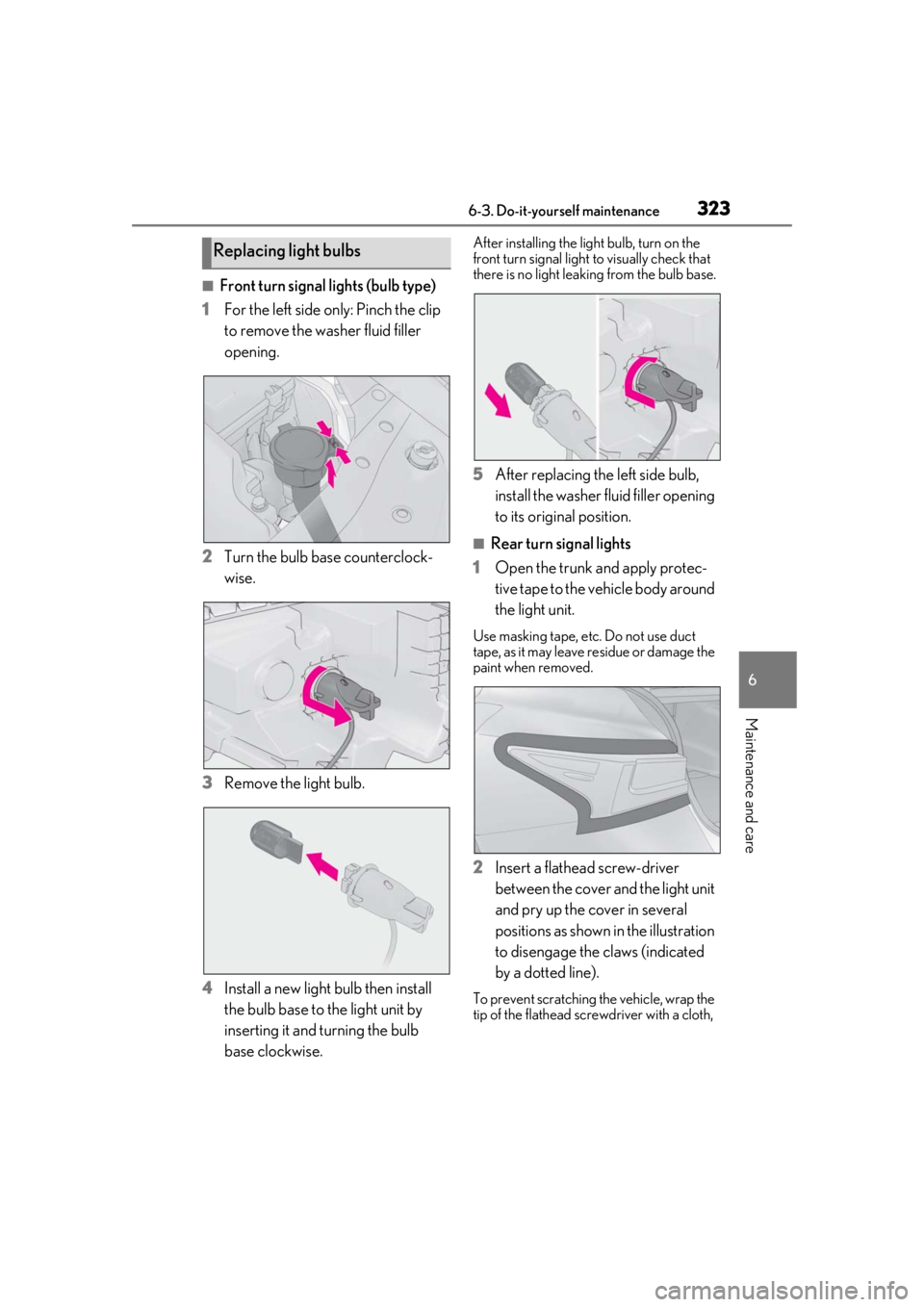
■Front turn signal lights (bulb type)
1 For the left side only: Pinch the clip
to remove the washer fluid filler
opening.
2 Turn the bulb base counterclock-
wise.
3 Remove the light bulb.
4 Install a new light bulb then install
the bulb base to the light unit by
inserting it and turning the bulb
base clockwise.
After installing the light bulb, turn on the
front turn signal light to visually check that
there is no light leaking from the bulb base.
5 After replacing the left side bulb,
install the washer fluid filler opening
to its original position.
■Rear turn signal lights
1 Open the trunk and apply protec-
tive tape to the vehicle body around
the light unit.
Use masking tape, etc. Do not use duct
tape, as it may leave residue or damage the
paint when removed.
2Insert a flathead screw-driver
between the cover and the light unit
and pry up the cover in several
positions as shown in the illustration
to disengage the claws (indicated
by a dotted line).
To prevent scratching the vehicle, wrap the
tip of the flathead scre wdriver with a cloth,
Replacing light bulbs
Page 325 of 436
3256-3. Do-it-yourself maintenance
6
Maintenance and care
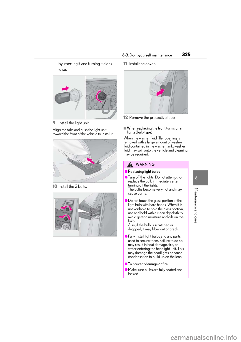
by inserting it and turning it clock-
wise.
9 Install the light unit.
Align the tabs and push the light unit
toward the front of the vehicle to install it.
10Install the 2 bolts. 11
Install the cover.
12 Remove the protective tape.
■When replacing the front turn signal
lights (bulb type)
When the washer fluid filler opening is
removed with a large amount of washer
fluid contained in the washer tank, washer
fluid may spill onto the vehicle and cleaning
may be required.
WARNING
■Replacing light bulbs
●Turn off the lights. Do not attempt to
replace the bulb immediately after
turning off the lights.
The bulbs become very hot and may
cause burns.
●Do not touch the glass portion of the
light bulb with bare hands. When it is
unavoidable to hold the glass portion,
use and hold with a clean dry cloth to
avoid getting moisture and oils on the
bulb.
Also, if the bulb is scratched or
dropped, it may blow out or crack.
●Fully install light bulbs and any parts
used to secure them. Failure to do so
may result in heat damage, fire, or
water entering the he adlight unit. This
may damage the headlights or cause
condensation to build up on the lens.
■To prevent damage or fire
●Make sure bulbs are fully seated and
locked.
Page 328 of 436
3287-1. Essential information
7-1.Essential information
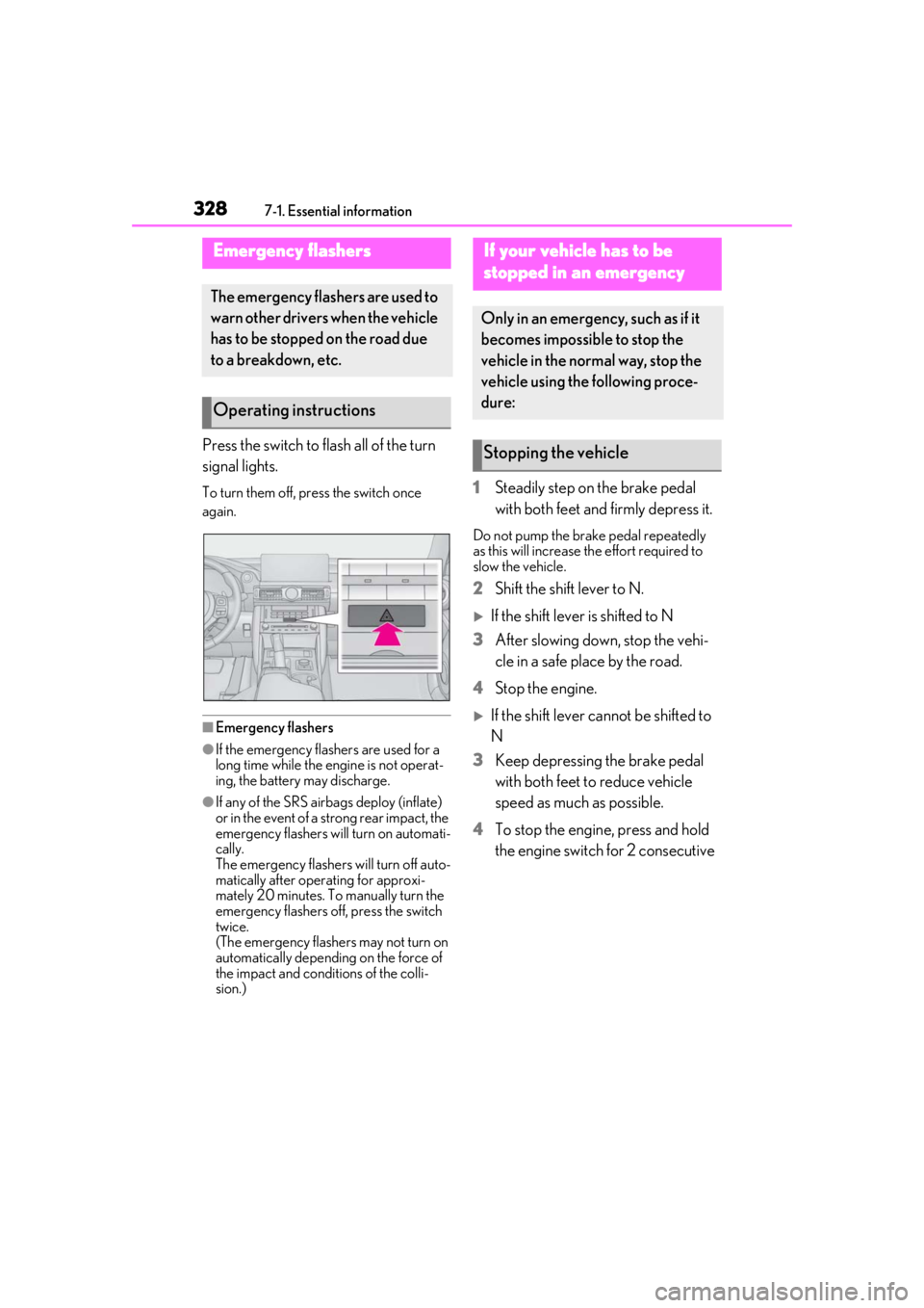
Press the switch to flash all of the turn
signal lights.
To turn them off, press the switch once
again.
■Emergency flashers
●If the emergency flashers are used for a
long time while the engine is not operat-
ing, the battery may discharge.
●If any of the SRS airbags deploy (inflate)
or in the event of a strong rear impact, the
emergency flashers will turn on automati-
cally.
The emergency flashers will turn off auto-
matically after operating for approxi-
mately 20 minutes. To manually turn the
emergency flashers off, press the switch
twice.
(The emergency flashers may not turn on
automatically depending on the force of
the impact and conditions of the colli-
sion.)
1 Steadily step on the brake pedal
with both feet and firmly depress it.
Do not pump the brake pedal repeatedly
as this will increase the effort required to
slow the vehicle.
2Shift the shift lever to N.
If the shift lever is shifted to N
3 After slowing down, stop the vehi-
cle in a safe place by the road.
4 Stop the engine.
If the shift lever cannot be shifted to
N
3 Keep depressing the brake pedal
with both feet to reduce vehicle
speed as much as possible.
4 To stop the engine, press and hold
the engine switch for 2 consecutive
Emergency flashers
The emergency flashers are used to
warn other drivers when the vehicle
has to be stopped on the road due
to a breakdown, etc.
Operating instructions
If your vehicle has to be
stopped in an emergency
Only in an emergency, such as if it
becomes impossible to stop the
vehicle in the normal way, stop the
vehicle using the following proce-
dure:
Stopping the vehicle