2021 HYUNDAI TUCSON high beam
[x] Cancel search: high beamPage 203 of 546

3-112
Convenient features of your vehicle
When the vehicle is driven on
a narrow curved road or rough
road.
When the vehicle is driven on
an uphill road or downhill
road.
When only part of the vehicle
in front is visible on a cross-
road or curved road.
When there is a traffic light,
reflecting sign, flashing sign
or mirror.
When the road conditions are
bad such as being wet or cov-
ered with snow.
When a vehicle suddenly
appears from a curve.
When the vehicle is tilted from
a flat tire or being towed.
When the Lane Keeping
Assist (LKA) system warning
light illuminates.
When the light from the on-
coming or front vehicle is not
detected because of exhaust
fume, smoke, fog, snow, etc.
When the front window is cov-
ered with foreign matters
such as ice, dust, fog, or is
damaged.
3) When the forward visibility is
poor. Such examples may
include:
When the headlamps of an on-
coming vehicle or a vehicle in
front is not detected due to
poor outside visibility (smog,
smoke, dust, fog, heavy rain,
snow, etc.).
When the windshield visibility
is poor.
Do not attempt to disassem-
ble the front view camera
without the assistance of an
authorized HYUNDAI dealer
technician. If camera is
removed for any reason, the
system may need to be re-cal-
ibrated. Have the system
inspected by an authorized
HYUNDAI dealer.
If the windshield of your vehi-
cle is replaced, most likely the
front view camera will need to
be re-calibrated. If this occurs,
have your vehicle inspected
and have the system re-cali-
brated by an authorized
HYUNDAI dealer.
Be careful that water doesn't
get into the High Beam Assist
(HBA) unit and do not remove
or damage related parts of the
High Beam Assist (HBA) sys-
tem.
WARNING
Page 204 of 546

3-113
Convenient features of your vehicle
3
Turn signals and lane change
signals
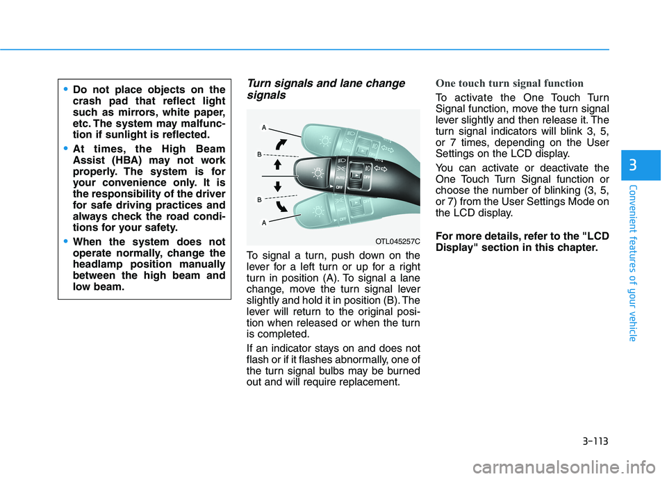
To signal a turn, push down on the
lever for a left turn or up for a right
turn in position (A). To signal a lane
change, move the turn signal lever
slightly and hold it in position (B). The
lever will return to the original posi-
tion when released or when the turn
is completed.
If an indicator stays on and does not
flash or if it flashes abnormally, one of
the turn signal bulbs may be burned
out and will require replacement.
One touch turn signal function
To activate the One Touch Turn
Signal function, move the turn signal
lever slightly and then release it. The
turn signal indicators will blink 3, 5,
or 7 times, depending on the User
Settings on the LCD display.
You can activate or deactivate the
One Touch Turn Signal function or
choose the number of blinking (3, 5,
or 7) from the User Settings Mode on
the LCD display.
For more details, refer to the "LCD
Display" section in this chapter.
OTL045257C
Do not place objects on the
crash pad that reflect light
such as mirrors, white paper,
etc. The system may malfunc-
tion if sunlight is reflected.
At times, the High Beam
Assist (HBA) may not work
properly. The system is for
your convenience only. It is
the responsibility of the driver
for safe driving practices and
always check the road condi-
tions for your safety.
When the system does not
operate normally, change the
headlamp position manually
between the high beam and
low beam.
Page 501 of 546

7-67
7
Maintenance
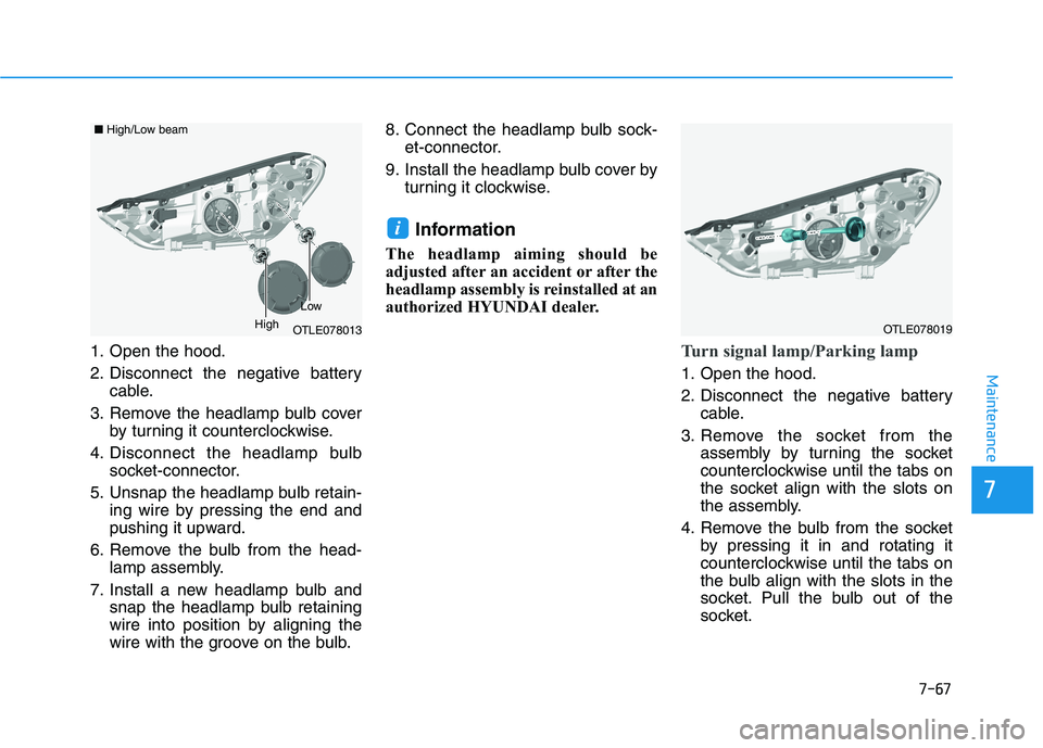
1. Open the hood.
2. Disconnect the negative batterycable.
3. Remove the headlamp bulb cover by turning it counterclockwise.
4. Disconnect the headlamp bulb socket-connector.
5. Unsnap the headlamp bulb retain- ing wire by pressing the end and
pushing it upward.
6. Remove the bulb from the head- lamp assembly.
7. Install a new headlamp bulb and snap the headlamp bulb retaining
wire into position by aligning the
wire with the groove on the bulb. 8. Connect the headlamp bulb sock-
et-connector.
9. Install the headlamp bulb cover by turning it clockwise.
Information
The headlamp aiming should be
adjusted after an accident or after the
headlamp assembly is reinstalled at an
authorized HYUNDAI dealer.
Turn signal lamp/Parking lamp
1. Open the hood.
2. Disconnect the negative batterycable.
3. Remove the socket from the assembly by turning the socket
counterclockwise until the tabs on
the socket align with the slots on
the assembly.
4. Remove the bulb from the socket by pressing it in and rotating it
counterclockwise until the tabs on
the bulb align with the slots in the
socket. Pull the bulb out of the
socket.
i
OTLE078013
■High/Low beam
Low
HighOTLE078019
Page 539 of 546

I-4
Driver Assist System.....................................................3-124
Rear View Monitor ...................................................3-124
Surround View Monitor ...........................................3-125
Driver Attention Warning (DAW) System......................5-96
Resetting the System ..................................................5-97
System Malfunction ...................................................5-98
System Setting and Activation ...................................5-96
System Standby ..........................................................5-98
Driver's front air bag .......................................................2-50
Electric Power Steering (EPS) ........................................3-21
Electronic Parking Brake (EPB) .....................................5-24
Electronic Stability Control (ESC) .................................5-35
Emission Control System ...............................................7-83
Crankcase Emission Control System .........................7-83
Evaporative Emission Control System Including
Onboard Refueling Vapor Recovery (ORVR) ........7-83
Exhaust Emission Control System .............................7-84
Engine ...............................................................................8-2
Engine compartment..................................................1-6, 7-3
Engine Coolant ...............................................................7-19
Changing Engine Coolant ..........................................7-22
Checking the Engine Coolant Level ..........................7-19
Engine Number ...............................................................8-12
Engine Oil .......................................................................7-17
Checking the Engine Oil and Filter ...........................7-18
Checking the Engine Oil Level ..................................7-17Explanation Of Scheduled Maintenance Items ..............7-14
Exterior Features .................................................3-47, 3-171
Fuel Filler Door ..........................................................3-48
Hood ...........................................................................3-47
Roof Rack.................................................................3-171
Exterior Lights ..............................................................3-107
AUTO headlamp position ........................................3-108
Battery saver function ..............................................3-114
Daytime running light (DRL) ..................................3-107
Front fog lamp ..........................................................3-114
Headlamp delay function..........................................3-115
Headlamp position....................................................3-109
High Beam Assist (HBA) .........................................3-110
High beam operation ................................................3-109
Lane change signals..................................................3-113
Parking lamp position ..............................................3-108
Turn signals ..............................................................3-113
Exterior overview .............................................................1-2
Floor Mat Anchor(s) .....................................................3-166
Forward Collision-Avoidance Assist (FCA) System
- Camera Type .............................................................5-60
FCA Sensor ................................................................5-65
FCA Warning Message and System Control..............5-63
Limitations of the System ..........................................5-68
System Not Operating ................................................5-67
System Setting and Activation ...................................5-60
Index
E
F