2021 HYUNDAI TUCSON HYBRID ESP
[x] Cancel search: ESPPage 505 of 630
Driver assistance system
7-146
WARNING
Take the following precautions when
using Reverse Parking Collision-
Avoidance Assist:
• Always pay extreme caution while
driving. The driver is responsible for
controlling the brake for safe driving.
• Always pay attention to road and
traffic conditions while driving,
whether or not there is a warning.
• Always look around your vehicle to
make sure there are no pedestrians
or objects before moving the vehicle.
• The performance of Reverse Parking
Collision-Avoidance Assist may
vary under certain conditions. If
vehicle speed is above 2 mph (4
km/h), Reverse Parking Collision-
Avoidance Assist will provide
collision avoidance assist only when
pedestrians are detected. Always
look around and pay attention when
backing up your vehicle.
• Some objects may not be detected
by the rear ultrasonic sensors due
to the objects distance, size or
material, all of which can limit the
effectiveness of the sensor.
• Reverse Parking Collision-Avoidance
Assist may not operate properly
or may operate unnecessarily
depending on the road conditions
and the surroundings.
• Do not solely rely on Reverse Parking
Collision-Avoidance Assist. Doing
so may lead to vehicle damage or
injuries.
CAUTION
• Noise may be heard when sudden
braking occurs to avoid a collision.
• If any other warning sound such
as the seat belt warning chime is
already generated, Reverse Parking
Collision-Avoidance Assist warning
may not sound.
• Reverse Parking Collision-Avoidance
Assist may not work properly if the
bumper has been damaged, replaced
or repaired.
• Reverse Parking Collision-Avoidance
Assist may not operate normally if
interfered by strong electromagnetic
waves.
• Playing the vehicle audio system at
high volume may prevent passengers
from hearing Reverse Parking
Collision-Avoidance Assist warning
sounds.
• Turn off Reverse Parking Collision-
Avoidance Assist when towing a
trailer. If towing and moving in
reverse, Reverse Parking Collision-
Avoidance Assist will activate as it
detects the trailer.
Page 519 of 630
Driver assistance system
7-160
• Parking in snow
ONX4070074
Snow may interfere with sensor
operation, or Remote Smart Parking
Assist may cancel if the road is
slippery while parking.
WARNING
Take the following precautions when
using Remote Smart Parking Assist:
• The driver is responsible for safe
parking and exit when using Remote
Smart Parking Assist. Make sure
there are no pedestrians, animals
or objects around the vehicle when
using the function.
• When using Remote Smart Parking
Assist, stay out of the way in the
direction the vehicle moves for your
safety.
• Always check surroundings when
using Remote Smart Parking Assist.
You may collide with pedestrians,
animals, or objects if they are near
the sensor or are in the sensor’s blind
spot area.
• A collision may occur if a pedestrian,
animal, or object suddenly appears
while Remote Smart Parking Assist is
operating.
• Do not use Remote Smart Parking
Assist when under the influence of
alcohol.
• Do not let children or other people to
use the smart key.
• If Remote Smart Parking Assist is
used continuously for a long period,
it may adversely affect Remote
Smart Parking Assist performance.
• Remote Smart Parking Assist may not
operate normally if the vehicle needs
wheel alignment adjustment such
as when the vehicle tilts to one side.
Have the vehicle inspected by an
authorized HYUNDAI dealer.
• Noise may be heard when braking
occurs by Remote Smart Parking
Assist or when the brake pedal is
depressed by the driver.
• Remote Smart Parking Assist may
suddenly apply the brake to avoid
collision.
• Use Remote Smart Parking Assist
only in a parking space that is large
enough for the vehicle to move
safely.
NOTICE
• If the 3rd stage warning (continuous
beep) of the Forward/Backward
Parking Distance Warning sounds
while Remote Smart Parking
Assist is operating, it means the
obstacle detected is close to your
vehicle. At this time, Remote Smart
Parking Assist will temporarily stop
operating. Make sure there are no
pedestrians, animals, or objects
around your vehicle.
• Depending on brake operation, the
stop lights may come on while the
vehicle is moving.
Page 526 of 630
Emergency situations
8-6
NOTICE
External power source using 12V battery
The use of external power accessories
may reduce performance and function
of the vehicle. Especially, the use of
dash cameras may shut off the power of
the vehicle prior to the dash camera’s
automatic shut-down.
If the power of the vehicle is shut off,
start the vehicle as explained. (refer to
“Using the 12V Battery Reset Switch”)
Jump Starting
In the event vehicle still does not have a
functional 12V battery (check if interior
lights will not turn on) then you can try
a jump start to the engine compartment
jumper terminals using a 12V booster
pack or jumper cables from another
vehicle’s 12V battery according to the
following instructions.
CAUTION
Jump starting can be dangerous if
done incorrectly. Follow the jump
starting procedure in this section to
avoid serious injury or damage to
your vehicle. If in doubt about how to
properly jump start your vehicle, we
strongly recommend that you have a
service technician or towing service do
it for you.
1.
Position the v
ehicles close enough
that the jumper cables will reach, but
do not allow the vehicles to touch.
Avoid fans or any moving parts in the
engine compartment at all times, even
when the vehicles are turned off.
2.
Turn o
ff all electrical devices such as
radios, lights, air conditioning, etc.
Put the vehicles in P (Park) and set the
parking brake. Turn both vehicles OFF.
ONX4080003
3. Connect the jumper cables in
the ex act sequence shown in the
illustration. First connect one jumper
cable to the red, positive (+) jumper
terminal of your vehicle (1).
4.
Connect the other end o
f the jumper
cable to the red, positive (+) battery/
jumper terminal of the assisting
vehicle (2).
5.
Connect the second jumper cable to
the black, nega
tive (-) battery/chassis
ground of the assisting vehicle (3).
6.
Connect the other end o
f the second
jumper cable to the black, negative (-)
chassis ground of your vehicle (4).
Do not allow the jumper cables to
contact anything except the correct
battery or jumper terminals or the
correct ground. Do not lean over the
battery when making connections.
Page 531 of 630
08
8-11
Tire pressure monitoring system
WARNING
Over-inflation or under-inflation can
reduce tire life, adversely affect vehicle
handling, and lead to sudden tire failure
that may cause loss of vehicle control
resulting in an accident.
Each tire, including the spare (if
provided), should be checked monthly
when cold and inflated to the inflation
pressure recommended by the vehicle
manufacturer on the vehicle placard
or tire inflation pressure label. (If your
vehicle has tires of a different size than
the size indicated on the vehicle placard
or tire inflation pressure label, you should
determine the proper tire inflation
pressure for those tires.)
As an added safety feature, your
vehicle has been equipped with a tire
pressure monitoring system (TPMS)
that illuminates a low tire pressure
telltale when one or more of your tires is
significantly under-inflated. Accordingly,
when the low tire pressure telltale
illuminates, you should stop and check
your tires as soon as possible, and inflate
them to the proper pressure. Driving on
a significantly under-inflated tire causes
the tire to overheat and can lead to tire
failure.
Under-inflation also reduces fuel
efficiency and tire tread life, and may
affect the vehicle’s handling and
stopping ability.
Please note that the TPMS is not a
substitute for proper tire maintenance,
and it is the driver’s responsibility to
maintain correct tire pressure, even if
under-inflation has not reached the level
to trigger illumination of the TPMS low
tire pressure telltale.
Your vehicle has also been equipped with
a TPMS malfunction indicator to indicate
when the system is not operating
properly. The TPMS malfunction
indicator is combined with the low
tire pressure telltale. When the system
detects a malfunction, the indicator will
flash for approximately one minute and
then remain continuously illuminated.
This sequence will continue upon
subsequent vehicle start-ups as long as
the malfunction exists.
When the malfunction indicator is
illuminated, the system may not be able
to detect or signal low tire pressure as
intended. TPMS malfunctions may occur
for a variety of reasons, including the
installation of replacement or alternate
tires or wheels on the vehicle that
prevent the TPMS from functioning
properly.
Always check the TPMS malfunction
telltale after replacing one or more tires
or wheels on your vehicle to ensure that
the replacement or alternate tires and
wheels allow the TPMS to continue to
function properly.
NOTICE
If any of the below happens, we
recommend that you have the system
checked by an authorized HYUNDAI
dealer.
1.
The Lo
w Tire Pressure Telltale/TPMS
Malfunction Indicator does not
illuminate for 3 seconds when the
Engine Start/Stop button is pressed
to the ON position or the vehicle is in
the ready (
) mode.
2.
The TPMS Malfunction Indica
tor
remains illuminated after blinking for
approximately 1 minute.
3.
The Lo
w Tire Pressure Position
Telltale remains illuminated.
Page 532 of 630
Emergency situations
8-12
Low tire pressure
warning light
Low tire pressure position and
tire pressure telltale
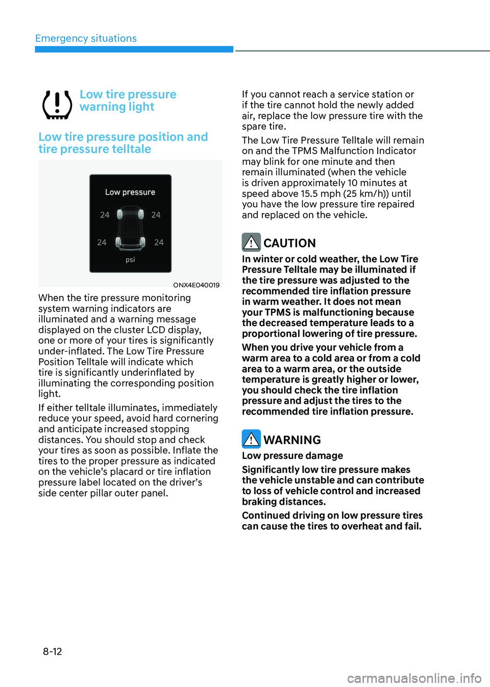
ONX4E040019
When the tire pressure monitoring
system warning indicators are
illuminated and a warning message
displayed on the cluster LCD display,
one or more of your tires is significantly
under-inflated. The Low Tire Pressure
Position Telltale will indicate which
tire is significantly underinflated by
illuminating the corresponding position
light.
If either telltale illuminates, immediately
reduce your speed, avoid hard cornering
and anticipate increased stopping
distances. You should stop and check
your tires as soon as possible. Inflate the
tires to the proper pressure as indicated
on the vehicle’s placard or tire inflation
pressure label located on the driver’s
side center pillar outer panel. If you cannot reach a service station or
if the tire cannot hold the newly added
air, replace the low pressure tire with the
spare tire.
The Low Tire Pressure Telltale will remain
on and the TPMS Malfunction Indicator
may blink for one minute and then
remain illuminated (when the vehicle
is driven approximately 10 minutes at
speed above 15.5 mph (25 km/h)) until
you have the low pressure tire repaired
and replaced on the vehicle.
CAUTION
In winter or cold weather, the Low Tire
Pressure Telltale may be illuminated if
the tire pressure was adjusted to the
recommended tire inflation pressure
in warm weather. It does not mean
your TPMS is malfunctioning because
the decreased temperature leads to a
proportional lowering of tire pressure.
When you drive your vehicle from a
warm area to a cold area or from a cold
area to a warm area, or the outside
temperature is greatly higher or lower,
you should check the tire inflation
pressure and adjust the tires to the
recommended tire inflation pressure.
WARNING
Low pressure damage
Significantly low tire pressure makes
the vehicle unstable and can contribute
to loss of vehicle control and increased
braking distances.
Continued driving on low pressure tires
can cause the tires to overheat and fail.
Page 534 of 630
Emergency situations
8-14
You may not be able to identify a tire
with low pressure by simply looking at it.
Always use a good quality tire pressure
gauge to measure. Please note that a tire
that is hot (from being driven) will have a
higher pressure measurement than a tire
that is cold.
A cold tire means the vehicle has been
sitting for 3 hours and driven for less
than 1 mile (1.6 km) in that 3 hour period.
Allow the tire to cool before measuring
the inflation pressure. Always be sure
the tire is cold before inflating to the
recommended pressure.
WARNING
• The TPMS cannot alert you to severe
and sudden tire damage caused by
external factors such as nails or road
debris.
• If you feel any vehicle instability,
immediately take your foot off
the accelerator, apply the brakes
gradually with light force, and slowly
move to a safe position off the road.
WARNING
Tampering with, modifying, or disabling
the Tire Pressure Monitoring System
(TPMS) components may interfere
with the system’s ability to warn the
driver of low tire pressure conditions
and/or TPMS malfunctions. Tampering
with, modifying, or disabling the Tire
Pressure Monitoring System (TPMS)
components may void the warranty for
that portion of the vehicle.
Information
This device complies with Part 15 of the
FCC rules.
Operation is subject to the following three
conditions:
1.
This device may not cause harmful
interference, and
2.
This device must accept any
interference r
eceived, including
interference that may cause undesired
operation.
3.
Changes or modifications not expr
essly
approved by the party responsible
for compliance could void the user’s
authority to operate the equipment.
Page 535 of 630
08
8-15
if you have a flaT Tire (wiTh Tire MobiliTy KiT,
if e qui
PPed)
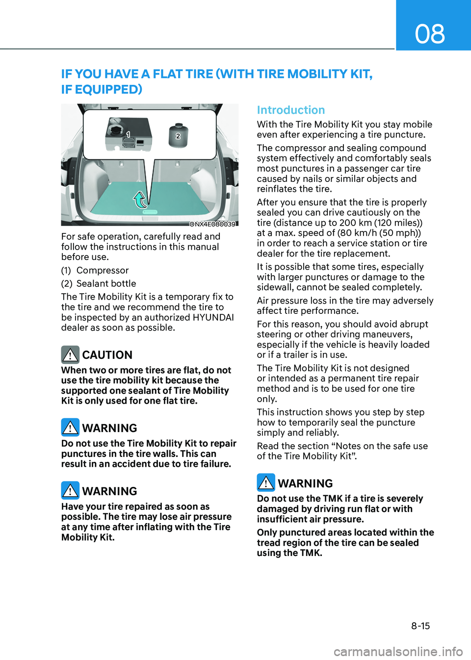
ONX4E080039
For safe operation, carefully read and
follow the instructions in this manual
before use.
(1)
Compressor
(2)
Sealant bo
ttle
The Tire Mobility Kit is a temporary fix to
the tire and we recommend the tire to
be inspected by an authorized HYUNDAI
dealer as soon as possible.
CAUTION
When two or more tires are flat, do not
use the tire mobility kit because the
supported one sealant of Tire Mobility
Kit is only used for one flat tire.
WARNING
Do not use the Tire Mobility Kit to repair
punctures in the tire walls. This can
result in an accident due to tire failure.
WARNING
Have your tire repaired as soon as
possible. The tire may lose air pressure
at any time after inflating with the Tire
Mobility Kit.
Introduction
With the Tire Mobility Kit you stay mobile
even after experiencing a tire puncture.
The compressor and sealing compound
system effectively and comfortably seals
most punctures in a passenger car tire
caused by nails or similar objects and
reinflates the tire.
After you ensure that the tire is properly
sealed you can drive cautiously on the
tire (distance up to 200 km (120 miles))
at a max. speed of (80 km/h (50 mph))
in order to reach a service station or tire
dealer for the tire replacement.
It is possible that some tires, especially
with larger punctures or damage to the
sidewall, cannot be sealed completely.
Air pressure loss in the tire may adversely
affect tire performance.
For this reason, you should avoid abrupt
steering or other driving maneuvers,
especially if the vehicle is heavily loaded
or if a trailer is in use.
The Tire Mobility Kit is not designed
or intended as a permanent tire repair
method and is to be used for one tire
only.
This instruction shows you step by step
how to temporarily seal the puncture
simply and reliably.
Read the section “Notes on the safe use
of the Tire Mobility Kit”.
WARNING
Do not use the TMK if a tire is severely
damaged by driving run flat or with
insufficient air pressure.
Only punctured areas located within the
tread region of the tire can be sealed
using the TMK.
Page 548 of 630
9. Maintenance
Engine compartment ........................................................................\
................9-3
Main tenance services
........................................................................\
............... 9-4
Owner’s responsibility ........................................................................\
........................ 9-4
Owner maint enance precautions........................................................................\
....... 9-4
Owner maintenance ........................................................................\
................. 9-5Owner maintenance schedule ........................................................................\
............9-5
Scheduled maintenance services .....................................................................9 -7Normal Maintenance Schedule ........................................................................\
.......... 9-8
Maint enance under severe usage conditions .......................................................... 9-
11
Explanation of scheduled maintenance items ..............................................9-13
E ngine oil
........................................................................\
.................................. 9-
15
Checking the engine oil level ........................................................................\
............9-15
Checking the engine oil and filt er ........................................................................\
..... 9-
16
Engine coolant/inverter coolant .....................................................................9-17Checking the coolant level ........................................................................\
................. 9-17
Changing coolan t ........................................................................\
............................... 9-
19
Hybrid Starter & Generator (HSG) belt ..........................................................9-20Checking the Hybrid Starter & Generator (HSG) belt .............................................9-20
Brake fluid ........................................................................\
............................... 9-20Checking the brake fluid level ........................................................................\
..........9-20
Washer fluid ........................................................................\
............................. 9-21Checking the washer fluid level ........................................................................\
........9-21
Air cleaner ........................................................................\
............................... 9-22Filter replacement ........................................................................\
..............................9-22
Cabin air filter ........................................................................\
..........................9-23Filter inspection ........................................................................\
.................................. 9-23
Filt er replacement ........................................................................\
.............................. 9-
23
Wiper blades ........................................................................\
...........................9-2 4Blade inspection ........................................................................\
.................................9-2 4
Blade replacement ........................................................................\
............................. 9
-24
Battery ........................................................................\
.....................................9-28Battery capacity label ........................................................................\
........................9-29
Ba ttery recharging ........................................................................\
............................. 9-
29
Reset items
........................................................................\
........................................ 9-
30
Maintenance
9