2021 HYUNDAI SONATA clock
[x] Cancel search: clockPage 448 of 546
07
7-13
Changing Tires
WARNING
A vehicle can slip or roll off of a jack
causing serious injury or death to you or
those nearby. Take the following safety
precautions:
• Never place any portion of your body
under a vehicle that is supported by
a jack.
• NEVER attempt to change a tire in
the lane of traffic. ALWAYS move the
vehicle completely off the road on
level, firm ground away from traffic
before trying to change a tire. If you
cannot find a level, firm place off
the road, call a towing service for
assistance.
• Be sure to use the jack provided with
the vehicle.
• ALWAYS place the jack on the
designated jacking positions on the
vehicle and NEVER on the bumpers
or any other part of the vehicle for
jacking support.
• Do not start or run the engine while
the vehicle is on the jack.
• Do not allow anyone to remain in the
vehicle while it is on the jack.
• Keep children away from the road
and the vehicle. Follow these steps to change your
vehicle’s tire:
1.
P
ark on a level, firm surface.
2. M ove the shift button into P (Park)
or into R (Reverse) if equipped with
a manual transmission, apply the
parking brake, and place the ignition
switch in the LOCK/OFF position.
3.
Pr
ess the hazard warning flasher
button.
4.
R
emove the wheel lug nut wrench,
jack, jack handle, and spare tire from
the vehicle.
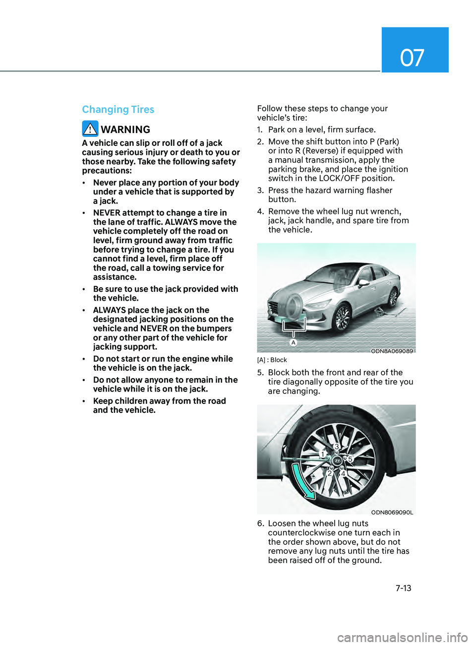
ODN8A069089[A] : Block
5. Block bo th the front and rear of the
tire diagonally opposite of the tire you
are changing.
ODN8069090L
6. Loosen the wheel lug nuts counterclockwise one turn each in
the order shown above, but do not
remove any lug nuts until the tire has
been raised off of the ground.
Page 449 of 546
Emergency Situations
7-14
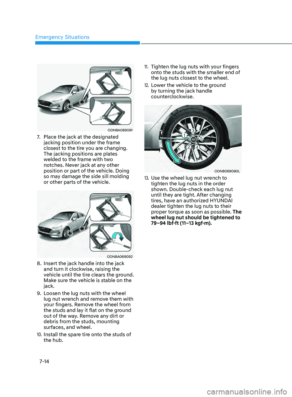
ODN8A069091
7. Place the jack at the designated
jacking position under the frame
closest to the tire you are changing.
The jacking positions are plates
welded to the frame with two
notches. Never jack at any other
position or part of the vehicle. Doing
so may damage the side sill molding
or other parts of the vehicle.
ODN8A069092
8. Insert the jack handle in to the jack
and turn it clockwise, raising the
vehicle until the tire clears the ground.
Make sure the vehicle is stable on the
jack.
9.
L
oosen the lug nuts with the wheel
lug nut wrench and remove them with
your fingers. Remove the wheel from
the studs and lay it flat on the ground
out of the way. Remove any dirt or
debris from the studs, mounting
surfaces, and wheel.
10. Install the spare tire onto the studs of
the hub.
11. Tighten the lug nuts with your fingers
onto the studs with the smaller end of
the lug nuts closest to the wheel.
12. Lower the vehicle to the ground
by turning the jack handle
counterclockwise.
ODN8069090L
13. Use the wheel lug nut wrench to
tighten the lug nuts in the order
shown. Double-check each lug nut
until they are tight. After changing
tires, have an authorized HYUNDAI
dealer tighten the lug nuts to their
proper torque as soon as possible. The
wheel lug nut should be tightened to
79~94 lbf·ft (11~13 kgf·m).
Page 476 of 546
Maintenance
8-22
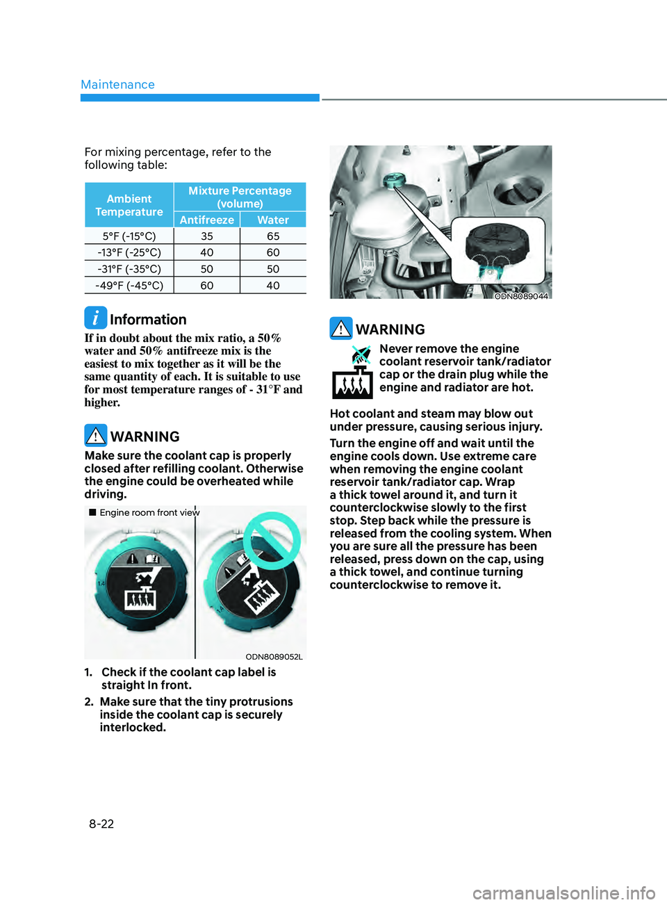
For mixing percentage, refer to the
following table:
Ambient
Temperature Mixture Percentage
(volume)
Antifreeze Water
5°F (-15°C) 35 65
-13°F (-25°C) 40 60
-31°F (-35°C) 50 50
-49°F (-45°C) 60 40
Information
If in doubt about the mix ratio, a 50%
water and 50% antifreeze mix is the
easiest to mix together as it will be the
same quantity of each. It is suitable to use
for most temperature ranges of - 31°F and
higher.
WARNING
Make sure the coolant cap is properly
closed after refilling coolant. Otherwise
the engine could be overheated while
driving.
„„Engine room front view
ODN8089052L
1. Check if the c oolant cap label is
straight In front.
2.
M
ake sure that the tiny protrusions
inside the coolant cap is securely
interlocked.
ODN8089044
WARNING
Never remove the engine
coolant reservoir tank/radiator
cap or the drain plug while the
engine and radiator are hot.
Hot coolant and steam may blow out
under pressure, causing serious injury.
Turn the engine off and wait until the
engine cools down. Use extreme care
when removing the engine coolant
reservoir tank/radiator cap. Wrap
a thick towel around it, and turn it
counterclockwise slowly to the first
stop. Step back while the pressure is
released from the cooling system. When
you are sure all the pressure has been
released, press down on the cap, using
a thick towel, and continue turning
counterclockwise to remove it.
Page 487 of 546
08
8-33
• The negative battery cable must
be removed first and installed last
when the battery is disconnected.
Disconnect the battery charger in the
following order:
1.
T
urn off the battery charger main
switch.
2.
U
nhook the negative clamp from
the negative battery terminal.
3.
U
nhook the positive clamp from
the positive battery terminal.
• Always use a genuine HYUNDAI
approved battery when you replace
the battery.
By jump starting
After a jump start from a good battery,
drive the vehicle for 20-30 minutes
before it is shutoff. The vehicle may
not restart if you shut it off before the
battery had a chance to adequately
recharge. See “Jump Starting” in chapter
7 for more information on jump starting
procedures.
Information
An inappropriately disposed
battery can be harmful to
the environment and human
health. Dispose of the battery
according to your local law(s) or
regulations.
Reset Features
The following items may need to be reset
after the battery has been discharged or
the battery has been disconnected. See
chapter 3 or 4 for:
• Power Windows
• Trip Computer
• Climate Control System
• Clock
• Audio System
• Sunroof
Page 513 of 546
08
8-59
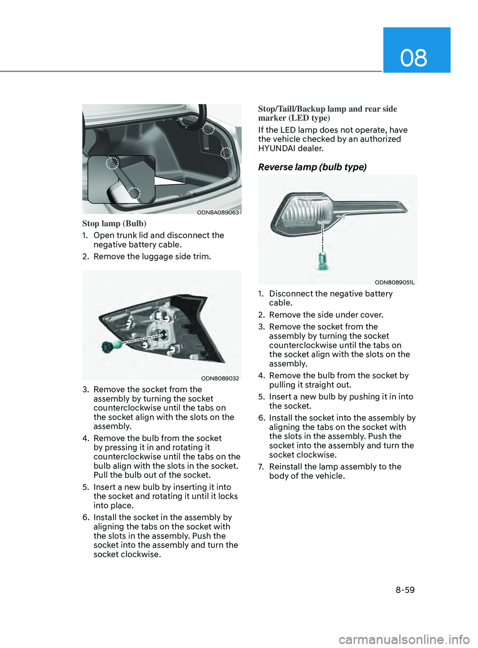
ODN8A089063
Stop lamp (Bulb)
1.
Open trunk lid and disconnect the
nega
tive battery cable.
2.
R
emove the luggage side trim.
ODN8089032
3. Remove the socket from the assembly by turning the socket
counterclockwise until the tabs on
the socket align with the slots on the
assembly.
4.
R
emove the bulb from the socket
by pressing it in and rotating it
counterclockwise until the tabs on the
bulb align with the slots in the socket.
Pull the bulb out of the socket.
5.
Insert a ne
w bulb by inserting it into
the socket and rotating it until it locks
into place.
6.
Ins
tall the socket in the assembly by
aligning the tabs on the socket with
the slots in the assembly. Push the
socket into the assembly and turn the
socket clockwise. Stop/Taill/Backup lamp and rear side
marker (LED type)
If the LED lamp does not operate, have
the vehicle checked by an authorized
HYUNDAI dealer.
Reverse lamp (bulb type)
ODN8089051L
1. Disconnect the nega
tive battery
cable.
2.
R
emove the side under cover.
3.
R
emove the socket from the
assembly by turning the socket
counterclockwise until the tabs on
the socket align with the slots on the
assembly.
4.
R
emove the bulb from the socket by
pulling it straight out.
5.
Insert a ne
w bulb by pushing it in into
the socket.
6.
Ins
tall the socket into the assembly by
aligning the tabs on the socket with
the slots in the assembly. Push the
socket into the assembly and turn the
socket clockwise.
7.
R
einstall the lamp assembly to the
body of the vehicle.
Page 533 of 546
I
I-5
Clock ........................................................................\
..........................................5-150
Clothes hanger
........................................................................\
........................... 5-150
Crankcase emission control system
..................................................................... 8-70
Cup holder
........................................................................\
................................. 5-145
Curtain air bags
........................................................................\
............................ 3-41
D
Daytime running light (DRL)
........................................................................\
...... 5-74
Declaration of conformity........................................................................\
............ 6-79 The radio frequency components (Rear Corner Radar) complies
...................6-79
Defroster
........................................................................\
.................................... 5-142
Dimensions
........................................................................\
.................................... 2-7
Door locks
........................................................................\
.................................... 5-31
Central door lock/unlock switch
..................................................................... 5-33
Child-protector rear door lock
........................................................................\
. 5-35
Auto door lock/unlock features
....................................................................... 5-34
Operating door locks from outside the vehicle
...............................................5-31
Operating door locks from inside the vehicle
.................................................5-32
Rear Occupant Alert (ROA) system
................................................................ 5-36
Vehicle Auto-Shut Off Function
..................................................................... 5-37
Drive mode integrated control system
................................................................ 6-37
Drive mode
........................................................................\
.............................. 6-37
Driver Attention Warning (DAW)
...................................................................... 6-86
Leading vehicle departure alert
....................................................................... 6-91
Driver position memory system........................................................................\
... 5-39 Storing positions into memory
........................................................................\
5-39
Easy access function
........................................................................\
............... 5-41
Driver’s air bag
........................................................................\
............................ 3-39
Driving at night
........................................................................\
.......................... 6-141
Driving in flooded areas
........................................................................\
............ 6-142
Driving in the rain
........................................................................\
...................... 6-141
E
Electric Power Steering (EPS)
........................................................................\
..... 5-42
Electronic Stability Control (ESC)
...................................................................... 6-29
Emergency towing
........................................................................\
....................... 7-19
Emergency trunk safety release
........................................................................\
... 5-66
Page 537 of 546
I
I-9
Instrument cluster ........................................................................\
.......................... 4-2
Instrument cluster illumination
........................................................................\
. 4-3
Gauges and meters
........................................................................\
.................... 4-3
Transmission shift indicator
........................................................................\
...... 4-6
Warning and indicator lights
........................................................................\
..... 4-7
LCD display messages
........................................................................\
............ 4-15
LCD display (Type A, B)
........................................................................\
........ 4-19
LCD display (Type C)
........................................................................\
............. 4-34
Instrument panel fuse replacement
...................................................................... 8-49
Instrument panel overview
........................................................................\
............ 2-5
Interior care
........................................................................\
.................................. 8-67
Interior features
........................................................................\
.......................... 5-145
Cup holder
........................................................................\
............................. 5-145
Sunvisor........................................................................\
................................. 5-146
Power outlet
........................................................................\
.......................... 5-146
USB charger
........................................................................\
.......................... 5-147
Wireless cellular phone charging system
......................................................5-148
Clock
........................................................................\
..................................... 5-150
Clothes hanger
........................................................................\
....................... 5-150
Floor mat anchor(s)
........................................................................\
............... 5-151
Interior lights
........................................................................\
............................... 5-80
Front lamps........................................................................\
.............................. 5-81
Rear lamps
........................................................................\
............................... 5-81
Luggage compartment lamp
........................................................................\
.... 5-82
Vanity mirror lamp
........................................................................\
.................. 5-82
Interior overview
........................................................................\
........................... 2-4
ISG (Idle Stop and Go) system
........................................................................\
.... 6-33
J
Jack and tools
........................................................................\
............................... 7-12
Jump starting
........................................................................\
.................................. 7-4
K
Key ignition switch
........................................................................\
........................ 6-6