Page 504 of 546

Maintenance
8-50
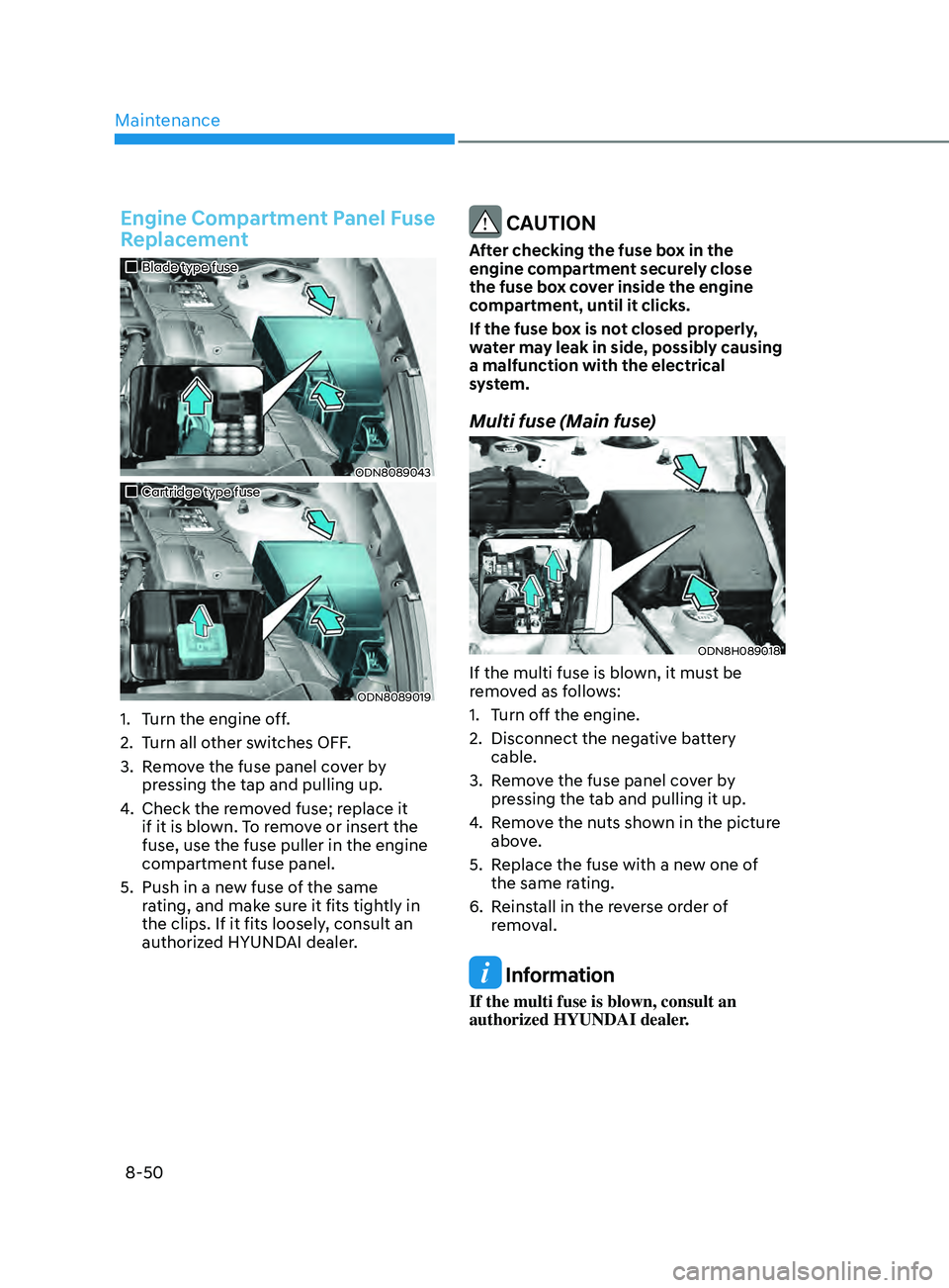
Engine Compartment Panel Fuse
Replacement
„„Blade type fuse
ODN8089043
„„Cartridge type fuse
ODN8089019
1. Turn the engine off.
2.
T
urn all other switches OFF.
3.
R
emove the fuse panel cover by
pressing the tap and pulling up.
4.
Check the r
emoved fuse; replace it
if it is blown. To remove or insert the
fuse, use the fuse puller in the engine
compartment fuse panel.
5.
Push in a ne
w fuse of the same
rating, and make sure it fits tightly in
the clips. If it fits loosely, consult an
authorized HYUNDAI dealer.
CAUTION
After checking the fuse box in the
engine compartment securely close
the fuse box cover inside the engine
compartment, until it clicks.
If the fuse box is not closed properly,
water may leak in side, possibly causing
a malfunction with the electrical
system.
Multi fuse (Main fuse)
ODN8H089018
If the multi fuse is blown, it must be
removed as follows:
1.
T
urn off the engine.
2.
Disconnect the nega
tive battery
cable.
3.
R
emove the fuse panel cover by
pressing the tab and pulling it up.
4.
R
emove the nuts shown in the picture
above.
5.
R
eplace the fuse with a new one of
the same rating.
6.
R
einstall in the reverse order of
removal.
Information
If the multi fuse is blown, consult an
authorized HYUNDAI dealer.
Page 524 of 546

Maintenance
8-70
1. Crankcase Emission Control System
The positive crankcase ventilation system
is employed to prevent air pollution
caused by blow-by gases being emitted
from the crankcase. This system supplies
fresh filtered air to the crankcase through
the air intake hose. Inside the crankcase,
the fresh air mixes with blow-by gases,
which then pass through the PCV valve
into the induction system.
2. Evaporative Emission Control System Including Onboard
Refueling Vapor Recovery
(ORVR)
The Evaporative Emission Control System
is designed to prevent fuel vapors from
escaping into the atmosphere. The
ORVR system is designed to allow the
vapors from the fuel tank to be loaded
into a canister while refueling at the gas
station, preventing the escape of fuel
vapors into the atmosphere.
Canister
Fuel vapors generated inside the fuel
tank are absorbed and stored in the
onboard canister. When the engine is
running, the fuel vapors absorbed in the
canister are drawn into the surge tank
through the purge control solenoid valve.
Purge Control Solenoid Valve (PCSV)
The purge control solenoid valve
is controlled by the Engine Control
Module (ECM); when the engine coolant
temperature is low during idling, the
PCSV closes so that evaporated fuel
is not taken into the engine. After the
engine warms-up during ordinary
driving, the PCSV opens to introduce
evaporated fuel to the engine.
3. Exhaust Emission Control System
The Exhaust Emission Control System is
a highly effective system which controls
exhaust emissions while maintaining
good vehicle performance.
When the engine starts or fails to start,
excessive attempts to restart the engine
may cause damage to the emission
system.
Engine exhaust (carbon monoxide)
precautions
• Carbon monoxide can be present
with other exhaust fumes. If you smell
exhaust fumes of any kind in your
vehicle, drive with all the windows
fully open. Have your vehicle checked
and repaired immediately.
WARNING
Engine exhaust gases contain carbon
monoxide (CO). Though colorless and
odorless, it is dangerous and could be
lethal if inhaled. Follow the instructions
on this page to avoid CO poisoning.
WARNING
CALIFORNIA PROPOSITION 65
WARNING
Engine exhaust and a wide variety of
automobile components and parts,
including components found in the
interior furnishings in a vehicle, contain
or emit chemicals known to the State
of California to cause cancer and
birth defects and reproductive harm.
In addition, certain fluids contained
in vehicles and certain products of
component wear contain or emit
chemicals known to the State of
California to cause cancer and birth
defects or other reproductive harm.
Page 538 of 546

Index
I-10
L
LabelVehicle certification label
........................................................................\
........ 2-13
Tire specification and pressure label
............................................................... 2-14
Refrigerant label
........................................................................\
...................... 2-15
Lane change signals
........................................................................\
..................... 5-79
Lane Following Assist (LFA)
........................................................................\
.... 6-116
Lane Keeping Assist (LKA)
........................................................................\
........ 6-59
LCD display (T
ype A, B) ........................................................................\
............. 4-19
LCD display control
........................................................................\
................ 4-19
LCD display modes
........................................................................\
................. 4-20
Trip computer
........................................................................\
.......................... 4-31
LCD display (Type C)
........................................................................\
................. 4-34
LCD display control
........................................................................\
................ 4-34
View modes
........................................................................\
............................. 4-35
Utility view mode
........................................................................\
.................... 4-36
Option menu
........................................................................\
............................ 4-38
User settings mode
........................................................................\
.................. 4-39
LCD display messages
........................................................................\
................. 4-15
Shift to P
or N to start engine
........................................................................\
.. 4-15
Shift to P
........................................................................\
.................................. 4-15
Low key battery........................................................................\
....................... 4-15
Press brake pedal to start engine
..................................................................... 4-15
Key not in vehicle
........................................................................\
................... 4-16
Key not detected
........................................................................\
...................... 4-16
Press START button again
........................................................................\
...... 4-16
Press START button with key
........................................................................\
. 4-16
Battery discharging due to external electrical devices
....................................4-16
Check BRAKE SWITCH fuse
........................................................................\
4-16
Door, Hood, Trunk open indicator
.................................................................. 4-17
Sunroof open indicator
........................................................................\
............ 4-17
Lights mode
........................................................................\
............................. 4-17
Wiper mode
........................................................................\
............................. 4-18
Low pressure
........................................................................\
........................... 4-17