2021 HYUNDAI SANTA FE HYBRID fuse
[x] Cancel search: fusePage 24 of 598
Foreword / Hybrid System Overview
1-20
SAFETY PRECAUTIONS FOR HYBRID SYSTEM
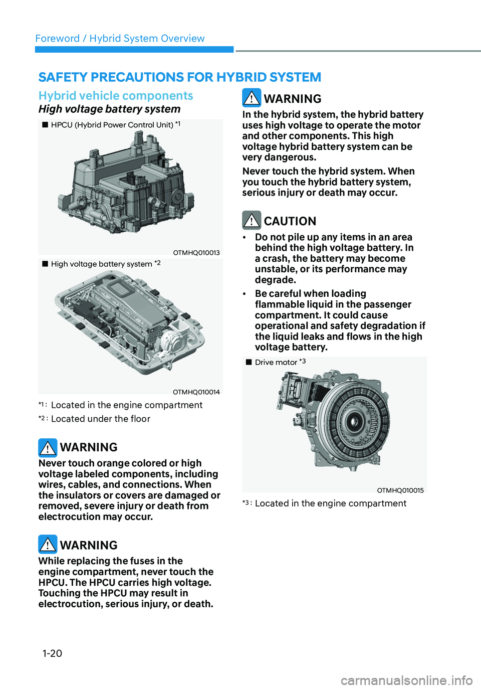
Hybrid vehicle components
High voltage battery system
„„HPCU (Hybrid Power Control Unit) *1
OTMHQ010013
„„High voltage battery system *2
OTMHQ010014
*1 : Located in the engine compartment
*2 : Located under the floor
WARNING
Never touch orange colored or high
voltage labeled components, including
wires, cables, and connections. When
the insulators or covers are damaged or
removed, severe injury or death from
electrocution may occur.
WARNING
While replacing the fuses in the
engine compartment, never touch the
HPCU. The HPCU carries high voltage.
Touching the HPCU may result in
electrocution, serious injury, or death.
WARNING
In the hybrid system, the hybrid battery
uses high voltage to operate the motor
and other components. This high
voltage hybrid battery system can be
very dangerous.
Never touch the hybrid system. When
you touch the hybrid battery system,
serious injury or death may occur.
CAUTION
• Do not pile up any items in an area
behind the high voltage battery. In
a crash, the battery may become
unstable, or its performance may
degrade.
• Be careful when loading
flammable liquid in the passenger
compartment. It could cause
operational and safety degradation if
the liquid leaks and flows in the high
voltage battery.
„„Drive motor *3
OTMHQ010015
*3 : Located in the engine compartment
Page 26 of 598
Foreword / Hybrid System Overview
1-22
NOTICE
• When the vehicle is paint baked, do
not bake over 30 minutes in 158°F
(70°C) or 20 minutes in 176°F (80°C)
degree.
• Do not wash the engine
compartment, using water. Water
may cause an electric shock and
damage the electronic components.
WARNING
This hybrid vehicle uses the hybrid
battery system inverter and converter
to generate high voltage. High voltage
in the hybrid battery system is very
dangerous and may cause severe burns
and electric shock. This may result in
serious injury or death.
• For your safety, never touch,
replace, disassemble or remove the
hybrid battery system including
components, cables and connectors.
Severe burns or electric shock may
result in serious injury or death when
you fail to follow this warning.
• When the hybrid battery system
operates, the hybrid battery system
can be hot. Always be careful
because burns or electric shock may
be caused by high voltage.
• Do not spill liquid on the HPCU, HSG,
motor and fuses. If the hybrid system
components come in contact with
liquid, it may result in electric shock.
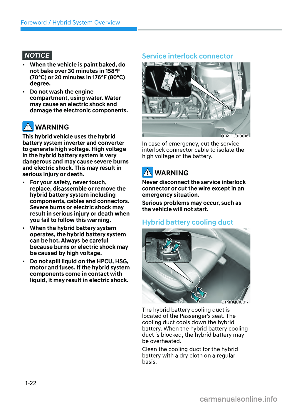
Service interlock connector
OTMHQ010016
In case of emergency, cut the service
interlock connector cable to isolate the
high voltage of the battery.
WARNING
Never disconnect the service interlock
connector or cut the wire except in an
emergency situation.
Serious problems may occur, such as
the vehicle will not start.
Hybrid battery cooling duct
OTMHQ010017
The hybrid battery cooling duct is
located of the Passenger’s seat. The
cooling duct cools down the hybrid
battery. When the hybrid battery cooling
duct is blocked, the hybrid battery may
be overheated.
Clean the cooling duct for the hybrid
battery with a dry cloth on a regular
basis.
Page 32 of 598
![HYUNDAI SANTA FE HYBRID 2021 Owners Manual 2-4
Vehicle Information, Consumer Information and Reporting Safety Defects
The actual shape may differ from the illustration.
OTMA020001C[A] : Type A, [B] : Type B
1. Inside door handle ..............](/manual-img/35/56184/w960_56184-31.png "HYUNDAI SANTA FE HYBRID 2021 Owners Manual 2-4
Vehicle Information, Consumer Information and Reporting Safety Defects
The actual shape may differ from the illustration.
OTMA020001C[A] : Type A, [B] : Type B
1. Inside door handle ..............")
2-4
Vehicle Information, Consumer Information and Reporting Safety Defects
The actual shape may differ from the illustration.
OTMA020001C[A] : Type A, [B] : Type B
1. Inside door handle ................................5-28
2. Power window switches ......................5-54
3. Power window lock switch .................5-56
/Electronic child safety lock button
....5-30
4. Side view mirror folding button ............5-51
5. Side view mirror control switch ............5-51
6. Central door lock switch ......................5-28
7. Instrument panel illumination control
switch
......................................................4-5
8. Lane Safety button ................................7-19
9. Power Liftgate open/close button ......5-66
10. ESC (Electronic Stability Control) OFF
button
....................................................6-28
11. EPB (Electronic Parking Brake) switch .6-19
12. Steering wheel ......................................5-36
13. Steering wheel tilt/telescopic switch ...5-37
14. Fuse box ................................................9-43
15. Hood release lever ................................5-63
16. Seat ..........................................................3-3
INTERIOR OVERVIEW
Page 35 of 598

2-7
02
„„Smartstream G 1.6 T-GDi HEV
The actual engine compartment in the vehicle may differ from the illustration.
OTMH090001
1. ECU
2. Engine coolant reservoir .......................9-17
3. Engine coolant reservoir cap ................9-17
4. Inverter coolant reservoir......................9-17
5. Brake fluid reservoir .............................9-20
6. Air cleaner .............................................9-22
7. Engine oil filler cap ................................9-15
8. Engine oil dipstick .................................9-15
9. Windshield washer fluid reservoir ........9-21
10. Fuse box .................................................9-41
11. Invert coolant reservoir cap ..................9-17
ENGINE COMPARTMENT
Page 114 of 598
 indicator light .........................")
EV mode indicator ........................................................................\
...........................4-19
Electronic Stability Control (ESC) indicator light ...................................................4-19
Electronic Stability Control (ESC) OFF indicator light ...........................................4-19
Immobilizer indicator light (with smart key) ..........................................................4-20
Downhill Brake Control (DBC) indicator light ........................................................4-20
Turn signal indicator light ........................................................................\
.................4-21
High beam indicator light ........................................................................\
................4-21
Low beam indicator light ........................................................................\
.................4-21
Light ON indicator light ........................................................................\
....................4-21
High Beam Assist indicator light ........................................................................\
......4-21
SPORT Mode indicator light ........................................................................\
............4-22
ECO Mode indicator light ........................................................................\
................4-22
SMART Mode indicator light ........................................................................\
...........4-22
LCD display messages ........................................................................\
.......................4-22
Shift to P ........................................................................\
...........................................4-22
Low key battery ........................................................................\
................................4-22
Press START button while turning wheel ...............................................................4-22
Check steering wheel lock system ........................................................................\
.4-22
Press brake pedal to start engine ........................................................................\
...4-23
Key not in vehicle ........................................................................\
.............................4-23
Key not detected ........................................................................\
..............................4-23
Press START button again
........................................................................\
...............4-23
Press START button with key ........................................................................\
...........4-23
Check BRAKE SWITCH fuse ........................................................................\
............4-23
12V battery discharging due to additional electrical devices ...............................4-23
Door, Hood, Liftgate open indicator .......................................................................4-24
Sunroof open indicator ........................................................................\
....................4-24
Low pressure ........................................................................\
....................................4-24
Wiper/Lights display ........................................................................\
........................4-25
Low washer fluid ........................................................................\
..............................4-25
Low fuel ........................................................................\
............................................4-25
Engine has overheated ........................................................................\
....................4-25
Check exhaust system ........................................................................\
.....................4-25
Check headlight ........................................................................\
...............................4-25
Check turn signal ........................................................................\
.............................4-25
Check brake light ........................................................................\
.............................4-25
Check headlamp LED ........................................................................\
......................4-26
4
Page 135 of 598
04
4-23
Press brake pedal to start engine (if
equipped)
This message is displayed if the Engine
Start/Stop button changes to the ACC
position twice by pressing the button
repeatedly without depressing the brake
pedal.
You can start the vehicle by depressing
the brake pedal and then pressing the
Engine Start/Stop button.
Key not in vehicle (if equipped)
This message is displayed if the smart
key is not in the vehicle when you press
the Engine Start/ Stop button.
When attempting to start the vehicle,
always have the smart key with you.
Key not detected (if equipped)
This message is displayed if the smart
key is not detected when you press the
Engine Start/Stop button.
Press START button again (if
equipped)
This message is displayed if you were
unable to start the vehicle when the
Engine Start/Stop button was pressed.
If this occurs, attempt to start the engine
by pressing the Engine Start/ Stop button
again.
If the warning message appears each
time you press the Engine Start/Stop
button, we recommend that you have
the vehicle inspected by an authorized
HYUNDAI dealer.
Press START button with key (if
equipped)
This message is displayed if you press
the Engine Start/Stop button while the
warning message “Key not detected” is
displayed.
At this time, the immobilizer indicator
light blinks.
Check BRAKE SWITCH fuse (if
equipped)
This message is displayed if the brake
switch fuse is disconnected.
You need to replace the fuse with a new
one before starting the engine.
If that is not possible, you can start the
engine by pressing the Engine Start/
Stop button for 10 seconds in the ACC
position.
12V battery discharging due to
additional electrical devices (if
equipped)
This message is displayed if the 12V
battery voltage is weak due to any
non-factory electrical accessories (ex.
dashboard camera) while parking. Be
careful that the battery is not discharged.
If the message appears after removing
the non-factory electrical accessories,
we recommend that you have the vehicle
inspected by an authorized HYUNDAI
dealer.
Page 215 of 598
05
5-57
ÃIf the power window lock button is
operated (indicator turns on), rear
passenger cannot open the rear door
(if equipped with the Electronic Child
Safety Lock System).
For more details, refer to “Electronic
Child Safety Lock System” system in this
chapter.
WARNING
Do not allow children to play with the
power windows. Keep the driver’s
door power window lock button in the
LOCK position. Serious injury or death
can result from unintentional window
operation by a child.
NOTICE
• To prevent possible damage to the
power window system, do not open
or close two windows or more at the
same time. This will also ensure the
longevity of the fuse.
• Never try to operate the main
switch on the driver’s door and the
individual door window switch in
opposite directions at the same time.
If this is done, the window will stop
and cannot be opened or closed.
Page 219 of 598
05
5-61
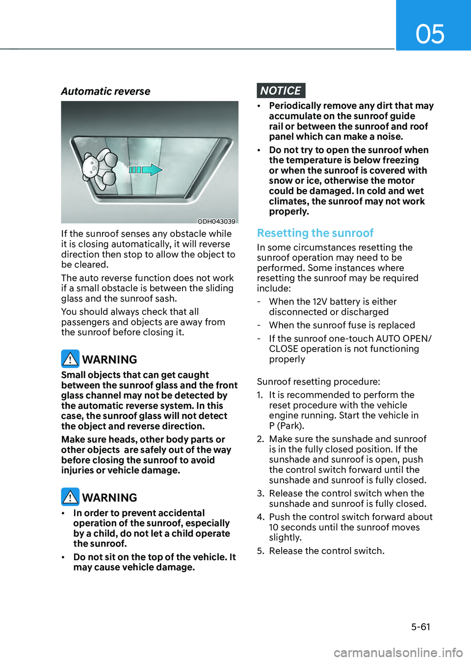
Automatic reverse
ODH043039
If the sunroof senses any obstacle while
it is closing automatically, it will reverse
direction then stop to allow the object to
be cleared.
The auto reverse function does not work
if a small obstacle is between the sliding
glass and the sunroof sash.
You should always check that all
passengers and objects are away from
the sunroof before closing it.
WARNING
Small objects that can get caught
between the sunroof glass and the front
glass channel may not be detected by
the automatic reverse system. In this
case, the sunroof glass will not detect
the object and reverse direction.
Make sure heads, other body parts or
other objects are safely out of the way
before closing the sunroof to avoid
injuries or vehicle damage.
WARNING
• In order to prevent accidental
operation of the sunroof, especially
by a child, do not let a child operate
the sunroof.
• Do not sit on the top of the vehicle. It
may cause vehicle damage.
NOTICE
• Periodically remove any dirt that may
accumulate on the sunroof guide
rail or between the sunroof and roof
panel which can make a noise.
• Do not try to open the sunroof when
the temperature is below freezing
or when the sunroof is covered with
snow or ice, otherwise the motor
could be damaged. In cold and wet
climates, the sunroof may not work
properly.
Resetting the sunroof
In some circumstances resetting the
sunroof operation may need to be
performed. Some instances where
resetting the sunroof may be required
include:
-When the 12V battery is either
disconnected or discharged
-When the sunroof fuse is replaced
-If the sunroof one-touch AUTO OPEN/
CLOSE operation is not functioning
properly
Sunroof resetting procedure:
1. It is recommended to perform the
reset procedure with the vehicle
engine running. Start the vehicle in
P (Park).
2. Make sure the sunshade and sunroof
is in the fully closed position. If the
sunshade and sunroof is open, push
the control switch forward until the
sunshade and sunroof is fully closed.
3. Release the control switch when the
sunshade and sunroof is fully closed.
4. Push the control switch forward about
10 seconds until the sunroof moves
slightly.
5. Release the control switch.