2021 HYUNDAI SANTA FE CALLIGRAPHY fuse
[x] Cancel search: fusePage 270 of 636
Convenient features
5-126
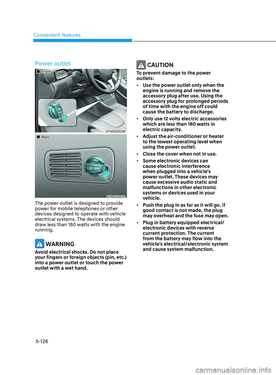
Power outlet
„„Front
OTM050026
„„Rear
OTM050031
The power outlet is designed to provide
power for mobile telephones or other
devices designed to operate with vehicle
electrical systems. The devices should
draw less than 180 watts with the engine
running.
WARNING
Avoid electrical shocks. Do not place
your fingers or foreign objects (pin, etc.)
into a power outlet or touch the power
outlet with a wet hand.
CAUTION
To prevent damage to the power
outlets:
• Use the power outlet only when the
engine is running and remove the
accessory plug after use. Using the
accessory plug for prolonged periods
of time with the engine off could
cause the battery to discharge.
• Only use 12 volts electric accessories
which are less than 180 watts in
electric capacity.
• Adjust the air-conditioner or heater
to the lowest operating level when
using the power outlet.
• Close the cover when not in use.
• Some electronic devices can
cause electronic interference
when plugged into a vehicle’s
power outlet. These devices may
cause excessive audio static and
malfunctions in other electronic
systems or devices used in your
vehicle.
• Push the plug in as far as it will go. If
good contact is not made, the plug
may overheat and the fuse may open.
• Plug in battery equipped electrical/
electronic devices with reverse
current protection. The current
from the battery may flow into the
vehicle’s electrical/electronic system
and cause system malfunction.
Page 300 of 636
Driving your vehicle
6-12
NOTICE
Do not turn off the engine immediately
after it has been subjected to a heavy
load. Doing so may cause severe
damage to the engine or turbo charger
unit.
NOTICE
To prevent damage to the vehicle:
• If the engine stalls while you are in
motion, do not attempt to shift the
gear to the P (Park) position.
If traffic and road conditions permit,
you may put the gear in N (Neutral)
while the vehicle is still moving and
press the Engine Start/Stop button in
an attempt to restart the engine.
• Do not push or tow your vehicle to
start the vehicle.
NOTICE
To prevent damage to the vehicle:
Do not press the Engine Start/Stop
button for more than 10 seconds except
when the stop lamp fuse is blown.
When the stop lamp fuse is blown,
you cannot normally start the engine.
Replace the fuse with a new one. If you
are not able to replace the fuse, you
can start the engine by pressing and
holding the Engine Start/Stop button
for 10 seconds with the Engine Start/
Stop button in the ACC position.
For your safety always depress the
brake pedal before starting the vehicle.
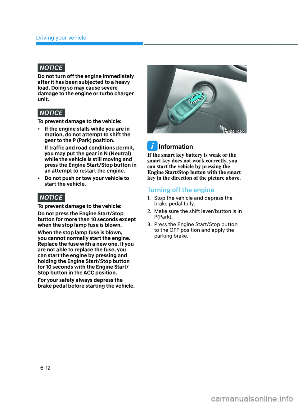
OTM060002
Information
If the smart key battery is weak or the
smart key does not work correctly, you
can start the vehicle by pressing the
Engine Start/Stop button with the smart
key in the direction of the picture above.
Turning off the engine
1. Stop the vehicle and depress the
br
ake pedal fully.
2.
Make sur
e the shift lever/button is in
P(Park).
3.
Press the E
ngine Start/Stop button
to the OFF position and apply the
parking brake.
Page 478 of 636
Driver assistance system
7-96
System malfunction and
limitations
System malfunction
When Surround View Monitor is not
working properly, or the screen flickers,
or the camera image does not display
normally, we recommend that the
system be inspected by an authorized
HYUNDAI dealer.
Limitations of the system
• When the vehicle is stopped for a long
time in winter or when the vehicle is
parked in an indoor parking lot, the
exhaust fumes may temporarily blur
the image.
• The screen may be displayed
abnormally, and an icon will appear at
the top left side of the screen under
the following circumstances:
- The liftga
te is opened
- The driver or fr
ont passenger door
is opened
- The side view mirr
or is folded
WARNING
• ALWAYS look around your vehicle
to make sure there are no objects
or obstacles before moving the
vehicle. What you see on the screen
may differ from the actual vehicle’s
location.
• The image shown on the screen may
differ from the actual distance of the
object. Make sure to directly check
the vehicle's surroundings for safety.
• When the rear view is displayed
while driving, an icon (
) appears at
the top right side of the infotainment
system screen to inform the driver
the rear view is being displayed. Do
not be confused with the front wide
view image.
• Surround View Monitor is designed
to be used on a flat surface.
Therefore, if used on roads with
different heights such as curbs
and speed bumps, the image in the
screen my not look correct.
• Always keep the camera lens clean.
If the lens is covered with foreign
material, it may adversely affect
camera performance and Surround
View Monitor may not operate
normally.
Page 552 of 636
Tires and wheels ........................................................................\
.....................9-32Tire care ........................................................................\
.............................................. 9-32
R ecommended cold tire inflation pressures ............................................................ 9-
32
Check tire inflation pressure
........................................................................\
............. 9-
33
Tire rotation
........................................................................\
........................................ 9-
34
Wheel alignment and tire balance
........................................................................\
.... 9-35
Tir
e replacement
........................................................................\
................................ 9-
35
Wheel replacement
........................................................................\
............................ 9-
36
Tire traction
........................................................................\
.....................................
...9-36
Tire maintenance
........................................................................\
............................... 9-
36
Tire sidewall labeling
........................................................................\
.......................... 9-
37
Low aspect ratio tires
........................................................................\
........................ 9-40
Fuses ........................................................................\
......................................... 9-41Instrument panel fuse replacement ........................................................................\
9-42
Engine compartmen t panel fuse replacement ....................................................... 9-43
F
use/relay panel description
........................................................................\
............ 9-44
Light bulbs ........................................................................\
................................ 9-51Headlamp, position lamp, turn signal lamp, Daytime Running Light (DRL)
replacement ........................................................................\
.....................................
..9-52
Side repeater lamp replacement
........................................................................\
..... 9-54
Rear combina
tion lamp replacement
...................................................................... 9-54
High moun
ted stop lamp replacement
.................................................................... 9-57
License pla
te lamp replacement
........................................................................\
...... 9-58
Int
erior light replacement
........................................................................\
................. 9-58
Appearance care ........................................................................\
..................... 9-60Exterior care ........................................................................\
...................................... 9-60
Int erior care ........................................................................\
....................................... 9-66
Emission control system........................................................................\
.........9-69
California perchlorate notice
........................................................................\
.. 9-72
Gasoline Particulate Filter (GPF) ........................................................................\
....... 9-72
9
Page 553 of 636
9-3
09
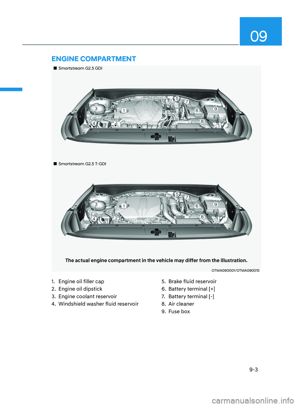
„„Smartstream G2.5 GDI
„„Smartstream G2.5 T-GDI
The actual engine compartment in the vehicle may differ from the illustration.
OTMA090001/OTMA090015
1. Engine oil filler cap
2.
Engine oil dips
tick
3.
Engine coolan
t reservoir
4.
Windshield washer fluid r
eservoir5. Brak
e fluid reservoir
6.
Batt
ery terminal [+]
7.
Batt
ery terminal [-]
8.
Air cleaner
9.
Fuse bo
x
ENGINE COMPARTMENT
Page 591 of 636
09
9-41
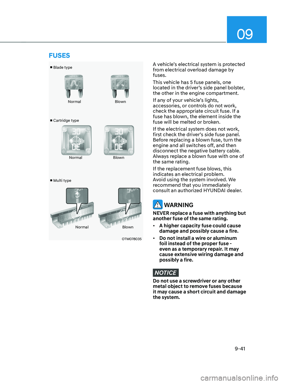
■ Blade type
■ Cartridge type
■ Multi type Normal
Blown
Normal Blown
Normal Blown
OTM078035
A vehicle’s electrical system is protected
from electrical overload damage by
fuses.
This vehicle has 5 fuse panels, one
located in the driver’s side panel bolster,
the other in the engine compartment.
If any of your vehicle’s lights,
accessories, or controls do not work,
check the appropriate circuit fuse. If a
fuse has blown, the element inside the
fuse will be melted or broken.
If the electrical system does not work,
first check the driver’s side fuse panel.
Before replacing a blown fuse, turn the
engine and all switches off, and then
disconnect the negative battery cable.
Always replace a blown fuse with one of
the same rating.
If the replacement fuse blows, this
indicates an electrical problem.
Avoid using the system involved. We
recommend that you immediately
consult an authorized HYUNDAI dealer.
WARNING
NEVER replace a fuse with anything but
another fuse of the same rating.
• A higher capacity fuse could cause
damage and possibly cause a fire.
• Do not install a wire or aluminum
foil instead of the proper fuse -
even as a temporary repair. It may
cause extensive wiring damage and
possibly a fire.
NOTICE
Do not use a screwdriver or any other
metal object to remove fuses because
it may cause a short circuit and damage
the system.
FUSES
Page 592 of 636
Maintenance
9-42
Instrument panel fuse
replacement
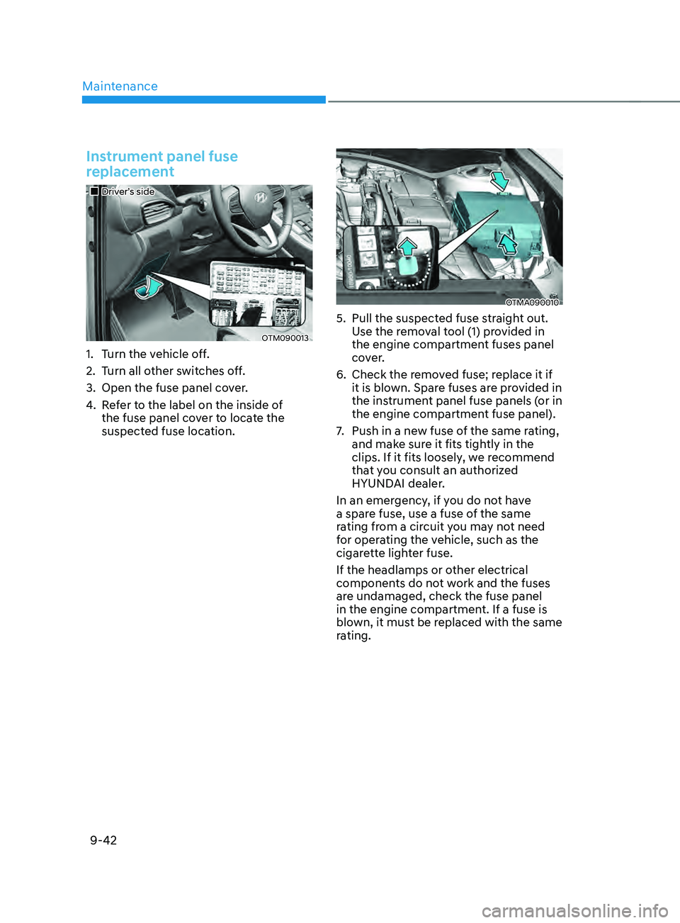
„„Driver’s side
OTM090013
1. Turn the vehicle off.
2.
Turn all o
ther switches off.
3.
Open the fuse panel cov
er.
4.
Re
fer to the label on the inside of
the fuse panel cover to locate the
suspected fuse location.
OTMA090010
5. Pull the suspected fuse s traight out.
Use the removal tool (1) provided in
the engine compartment fuses panel
cover.
6.
Check the remo
ved fuse; replace it if
it is blown. Spare fuses are provided in
the instrument panel fuse panels (or in
the engine compartment fuse panel).
7.
Push in a new fuse o
f the same rating,
and make sure it fits tightly in the
clips. If it fits loosely, we recommend
that you consult an authorized
HYUNDAI dealer.
In an emergency, if you do not have
a spare fuse, use a fuse of the same
rating from a circuit you may not need
for operating the vehicle, such as the
cigarette lighter fuse.
If the headlamps or other electrical
components do not work and the fuses
are undamaged, check the fuse panel
in the engine compartment. If a fuse is
blown, it must be replaced with the same
rating.
Page 593 of 636
09
9-43
Engine compartment panel fuse
replacement
Blade fuse / Cartridge fuse
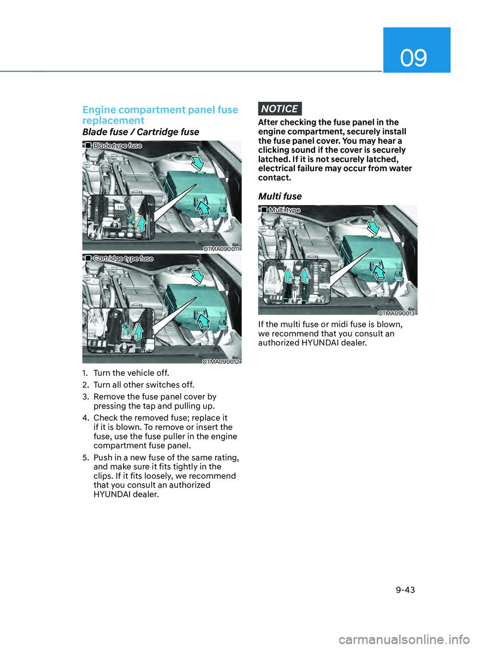
„„Blade type fuse
OTMA090011
„„Cartridge type fuse
OTMA090012
1. Turn the vehicle off.
2.
Turn all o
ther switches off.
3.
Remo
ve the fuse panel cover by
pressing the tap and pulling up.
4.
Check the remo
ved fuse; replace it
if it is blown. To remove or insert the
fuse, use the fuse puller in the engine
compartment fuse panel.
5.
Push in a new fuse o
f the same rating,
and make sure it fits tightly in the
clips. If it fits loosely, we recommend
that you consult an authorized
HYUNDAI dealer.
NOTICE
After checking the fuse panel in the
engine compartment, securely install
the fuse panel cover. You may hear a
clicking sound if the cover is securely
latched. If it is not securely latched,
electrical failure may occur from water
contact.
Multi fuse
„„Multi type
OTMA090013
If the multi fuse or midi fuse is blown,
we recommend that you consult an
authorized HYUNDAI dealer.