2021 HYUNDAI SANTA FE CALLIGRAPHY sensor
[x] Cancel search: sensorPage 531 of 636
08
8-13
If the indicators do not extinguish after a
few minutes, please visit an authorized
HYUNDAI dealer.
Each wheel is equipped with a tire
pressure sensor mounted inside the tire
behind the valve stem (except for the
spare tire). You must use TPMS specific
wheels. It is recommended that you
always have your tires serviced by an
authorized HYUNDAI dealer.
You may not be able to identify a tire
with low pressure by simply looking at it.
Always use a good quality tire pressure
gauge to measure. Please note that a tire
that is hot (from being driven) will have a
higher pressure measurement than a tire
that is cold.
A cold tire means the vehicle has been
sitting for 3 hours and driven for less
than 1 mile (1.6 km) in that 3 hour period.
Allow the tire to cool before measuring
the inflation pressure. Always be sure
the tire is cold before inflating to the
recommended pressure.
WARNING
• The TPMS cannot alert you to severe
and sudden tire damage caused by
external factors such as nails or road
debris.
• If you feel any vehicle instability,
immediately take your foot off
the accelerator, apply the brakes
gradually with light force, and slowly
move to a safe position off the road.
WARNING
Tampering with, modifying, or disabling
the Tire Pressure Monitoring System
(TPMS) components may interfere
with the system’s ability to warn the
driver of low tire pressure conditions
and/or TPMS malfunctions. Tampering
with, modifying, or disabling the Tire
Pressure Monitoring System (TPMS)
components may void the warranty for
that portion of the vehicle.
Information
This device complies with Part 15 of the
FCC rules.
Operation is subject to the following three
conditions:
1.
This device may not cause harmful
interference.
2.
This device must accept any
interference r
eceived, including
interference that may cause undesired
operation.
3.
Changes or modifications not expr
essly
approved by the party responsible
for compliance could void the user’s
authority to operate the equipment.
Page 547 of 636
08
8-29
Information
The pressure gauge may show higher than
actual reading when the compressor is
running. To get an accurate tire pressure,
the compressor needs to be turned off.
CAUTION
If the inflation pressure is not
maintained, drive the vehicle a second
time, refer to Distributing the sealant.
Then repeat steps 1 to 4.
Use of the TMK may be ineffectual for
tire damage larger than approximately
4 mm (0.16 in).
We recommend that you contact an
authorized HYUNDAI dealer if the tire
cannot be made roadworthy with the
Tire Mobility Kit.
WARNING
The tire inflation pressure must be
inflated to the proper pressure (Refer to
“Tire and Wheels” section in chapter 2).
If it is not, do not continue driving.
Call for road side service or towing.
CAUTION
Tire pressure sensor
The sealant on the tire pressure sensor
and wheel should be removed when
you replace the tire with a new one and
inspect the tire pressure sensors. We
recommend that you get this done at an
authorized dealer.
Information
When reinstalling the repaired or replaced
tire and wheel on the vehicle, tighten the
wheel bolt to 79~94 lbf.ft (11~13 kgf.m).
Page 573 of 636
09
9-23
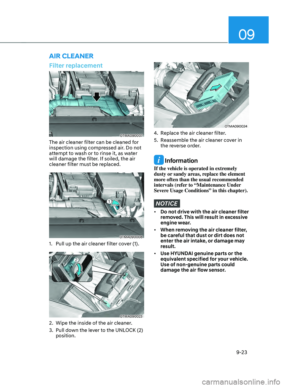
Filter replacement
OTMA090007
The air cleaner filter can be cleaned for
inspection using compressed air. Do not
attempt to wash or to rinse it, as water
will damage the filter. If soiled, the air
cleaner filter must be replaced.
OTMA090008
1. Pull up the air cleaner filter cover (1).
OTMA090023
2. Wipe the inside of the air cleaner .
3.
Pull down the le
ver to the UNLOCK (2)
position.
OTMA090024
4. Replace the air cleaner filter.
5.
Reassemble the air cleaner co
ver in
the reverse order.
Information
If the vehicle is operated in extremely
dusty or sandy areas, replace the element
more often than the usual recommended
intervals (refer to “Maintenance Under
Severe Usage Conditions” in this chapter).
NOTICE
• Do not drive with the air cleaner filter
removed. This will result in excessive
engine wear.
• When removing the air cleaner filter,
be careful that dust or dirt does not
enter the air intake, or damage may
result.
• Use HYUNDAI genuine parts or the
equivalent specified for your vehicle.
Use of non-genuine parts could
damage the air flow sensor.
AIR CLEANER
Page 595 of 636
09
9-45
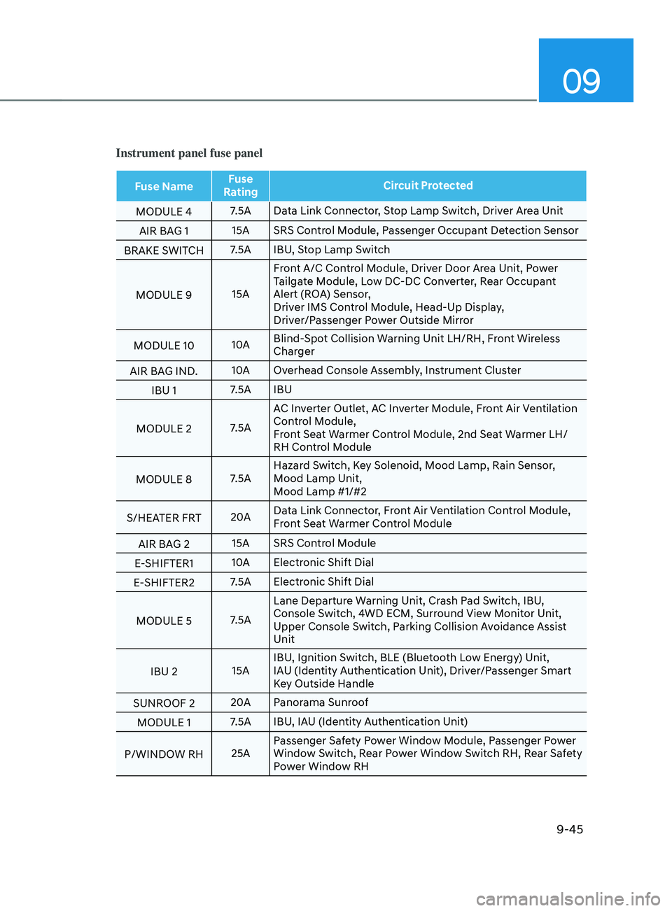
Instrument panel fuse panel
Fuse NameFuse
Rating Circuit Protected
MODULE 4 7.5A Data Link Connector, Stop Lamp Switch, Driver Area Unit
AIR BAG 1 15A SRS Control Module, Passenger Occupant Detection Sensor
BRAKE SWITCH 7.5A IBU, Stop Lamp Switch
MODULE 9 15AFront A/C Control Module, Driver Door Area Unit, Power
Tailgate Module, Low DC-DC Converter, Rear Occupant
Alert (ROA) Sensor,
Driver IMS Control Module, Head-Up Display,
Driver/Passenger Power Outside Mirror
MODULE 10 10ABlind-Spot Collision Warning Unit LH/RH, Front Wireless
Charger
AIR BAG IND. 10A
Overhead Console Assembly, Instrument Cluster
IBU 1 7.5A IBU
MODULE 2 7.5AAC Inverter Outlet, AC Inverter Module, Front Air Ventilation
Control Module,
Front Seat Warmer Control Module, 2nd Seat Warmer LH/
RH Control Module
MODULE 8 7.5AHazard Switch, Key Solenoid, Mood Lamp, Rain Sensor,
Mood Lamp Unit,
Mood Lamp #1/#2
S/HEATER FRT 20AData Link Connector, Front Air Ventilation Control Module,
Front Seat Warmer Control Module
AIR BAG 2 15A SRS Control Module
E-SHIFTER1 10A
Electronic Shift Dial
E-SHIFTER2 7.5A Electronic Shift Dial
MODULE 5 7.5ALane Departure Warning Unit, Crash Pad Switch, IBU,
Console Switch, 4WD ECM, Surround View Monitor Unit,
Upper Console Switch, Parking Collision Avoidance Assist
Unit
IBU 2 15AIBU, Ignition Switch, BLE (Bluetooth Low Energy) Unit,
IAU (Identity Authentication Unit), Driver/Passenger Smart
Key Outside Handle
SUNROOF 2 20A
Panorama Sunroof
MODULE 1 7.5A IBU, IAU (Identity Authentication Unit)
P/WINDOW RH 25APassenger Safety Power Window Module, Passenger Power
Window Switch, Rear Power Window Switch RH, Rear Safety
Power Window RH
Page 599 of 636
09
9-49
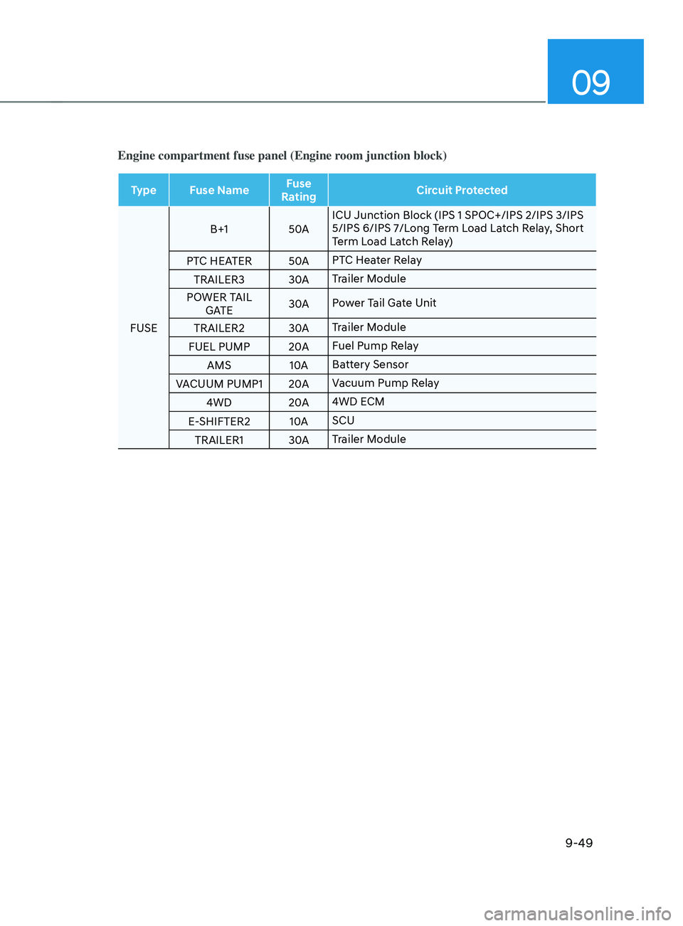
Engine compartment fuse panel (Engine room junction block)
Type Fuse NameFuse
Rating Circuit Protected
FUSE B+1
50AICU Junction Block (IPS 1 SPOC+/IPS 2/IPS 3/IPS
5/IPS 6/IPS 7/Long Term Load Latch Relay, Short
Term Load Latch Relay)
PTC HEATER 50APTC Heater Relay
TRAILER3 30ATrailer Module
POWER TAIL GATE 30A
Power Tail Gate Unit
TRAILER2 30ATrailer Module
FUEL PUMP 20AFuel Pump Relay
AMS 10ABattery Sensor
VACUUM PUMP1 20AVacuum Pump Relay
4WD 20A4WD ECM
E-SHIFTER2 10ASCU
TRAILER1 30ATrailer Module
Page 600 of 636
Maintenance
9-50
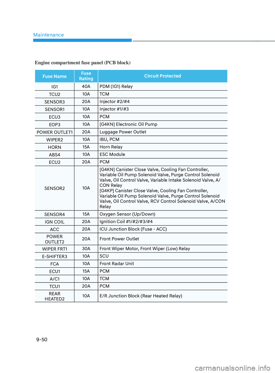
Engine compartment fuse panel (PCB block)
Fuse NameFuse
Rating Circuit Protected
IG1 40A
PDM (IG1) Relay
TCU2 10A
TCM
SENSOR3 20A
Injector #2/#4
SENSOR1 10A
Injector #1/#3
ECU3 10A
PCM
EOP3 10A
[G4KN] Electronic Oil Pump
POWER OUTLET1 20A
Luggage Power Outlet
WIPER2 10A
IBU, PCM
HORN 15A Horn Relay
ABS4 10A
ESC Module
ECU2 20A
PCM
SENSOR2 10A[G4KN] Canister Close Valve, Cooling Fan Controller,
Variable Oil Pump Solenoid Valve, Purge Control Solenoid
Valve, Oil Control Valve, Variable Intake Solenoid Valve, A/
CON Relay
[G4KP] Canister Close Valve, Cooling Fan Controller,
Variable Oil Pump Solenoid Valve, Purge Control Solenoid
Valve, Oil Control Valve, RCV Control Solenoid Valve, A/CON
Relay
SENSOR4 15A Oxygen Sensor (Up/Down)
IGN COIL 20A
Ignition Coil #1/#2/#3/#4
ACC 20A
ICU Junction Block (Fuse - ACC)
POWER
OUTLET2 20A
Front Power Outlet
WIPER FRT1 30A
Front Wiper Motor, Front Wiper (Low) Relay
E-SHIFTER3 10A
SCU
FCA 10A
Front Radar Unit
ECU1 15A PCM
A/C1 10A
TCM
TCU1 20A
PCM
REAR
HEATED2 10A
E/R Junction Block (Rear Heated Relay)
Page 610 of 636
Maintenance
9-60
Exterior care
Exterior general caution
It is very important to follow the label
directions when using any chemical
cleaner or polish. Read all warning and
caution statements that appear on the
label.
Finish maintenance
Washing
To help protect your vehicle’s finish from
rust and deterioration, wash it thoroughly
and frequently at least once a month
with lukewarm or cold water.
If you use your vehicle for off-road
driving, you should wash it after each
off-road trip. Pay special attention to the
removal of any accumulation of salt, dirt,
mud, and other foreign materials. Make
sure the drain holes in the lower edges
of the doors and rocker panels are kept
clear and clean.
Insects, tar, tree sap, bird droppings,
industrial pollution and similar deposits
can damage your vehicle’s finish if not
removed immediately.
Even prompt washing with plain water
may not completely remove all these
deposits. A mild soap, safe for use on
painted surfaces, should be used.
After washing, rinse the vehicle
thoroughly with lukewarm or cold water.
Do not allow soap to dry on the finish.High-pressure washing
•
When using high-pressure washers,
make sure to maintain sufficient
distance from the vehicle.
Insufficient clearance or excessive
pressure can lead to component
damage or water penetration.
• Do not spray the camera, sensors or
its surrounding area directly with a
high pressure washer. Shock applied
from high pressure water may cause
the device to not operate normally.
• Do not bring the nozzle tip close to
boots (rubber or plastic covers) or
connectors as they may be damaged
if they come into contact with high
pressure water.
WARNING
After washing the vehicle, test the
brakes while driving slowly to see
if they have been affected by water
before getting on the road. If braking
performance is impaired, dry the
brakes by applying them lightly while
maintaining a slow forward speed.
APPEARANCE CARE
Page 628 of 636
Index
I-6
Exterior features........................................................................\
......................... 5-136
Roof side rails ........................................................................\
.........................5-136
Exterior overview (I)
........................................................................\
..................... 2-2
Exterior overview (II)
........................................................................\
.................... 2-3
F
Forward Collision–A
voidance Assist (FCA) (Sensor fusion)
...............................7-2
System malfunction and limitations ................................................................. 7-10
System operation ........................................................................\
........................ 7-6
System settings ........................................................................\
........................... 7-4
Forward/Reverse Parking Distance
Warning (PDW)
.......................................7
-111
System malfunction and precautions ..............................................................7-1
13
System operation ........................................................................\
....................7-
111
System settings ........................................................................\
.......................7
-111
Four wheel drive (4WD)
........................................................................\
.............. 6-52
Emergency precautions ........................................................................\
............6-58
Four Wheel Drive (4WD) operation ................................................................6-53
Reducing the risk of a rollover ........................................................................\
. 6-59
Fuses
........................................................................\
............................................ 9-41
Engine compartment panel fuse replacement ...................................................9-43
Fuse/relay panel description ........................................................................\
..... 9-44
Instrument panel fuse replacement ...................................................................9-42
H
Hazard warning flasher
........................................................................\
.................. 8-2
Head-Up Display (HUD)
........................................................................\
............ 5-80
Head-up display information ........................................................................\
....5-80
Head-up display settings ........................................................................\
.......... 5-80
Precautions while using the head-up display ...................................................5-81
High Beam
Assist (HBA)
........................................................................\
........... 5-86
System malfunction and limitations .................................................................5-87
System operation ........................................................................\
...................... 5-87
System settings ........................................................................\
......................... 5-86
Highway Driving
Assist (HDA)
........................................................................\
. 7-81
System malfunction and limitations .................................................................7-85
System operation ........................................................................\
...................... 7-83
System settings ........................................................................\
......................... 7-82